 |
12V DC Basics By Bill "BillaVista" Ansell |
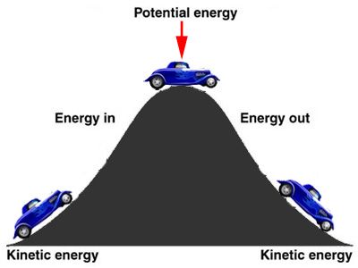 |
It may be some time since most of us learned about potential and kinetic energy, so they bear just a brief review. In the picture at left, the car going up the hill has kinetic energy - the energy of motion. When it stops at the top it has potential energy, even if we turn off the engine. This is due to gravity. If we push it over the hill, it rolls down the hill, "spending" the potential energy that it had at the top of the hill. The amount of potential energy at the top depends on the height of the hill - i.e. the difference between two points - the top of the hill and the bottom of the hill. We'll return to this concept of potential (stored) energy between two points later when we discuss voltage. |
||||||||||||||||
Electricity is just another form of energy, and like all forms, cannot be created nor destroyed - just converted form one form to another. And like most other forms of energy, we use electricity to power things. In the case of 12 volt direct-current (12V DC) automotive electricity, with which this article is concerned, we use it to power the vehicle itself (electric ignition); to power crucial devices such as starter motors, headlights, windshield wipers, and electric fans; and to power accessories such as radios, power windows, off-road lights, navigation systems, power seats, and more. There are a few basics we must understand before we look in detail at 12V DC systems. I'll keep this as brief as possible and try not to get off-topic, or dive into too much detail. We just need to establish a common base of knowledge that will allows us to discuss some of the more interesting and practical topics later in detail without confusion. ElectronsAll materials are made up of tiny "building blocks" known as atoms. All naturally occurring atoms contain particles called electrons, protons, and neutrons. |
|||||||||||||||||
|
|||||||||||||||||
Electrons have a negative (-) electric charge. Protons have a positive (+) electric charge. Neutrons have no electric charge. Electrons can be dislodged from atoms much more easily than protons or neutrons can. |
|||||||||||||||||
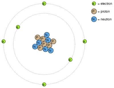 |
Stylized representation of a carbon atom showing protons, neutrons, and electrons. | ||||||||||||||||
Conductors & InsulatorsThe electrons in the atoms of different materials have different degrees of freedom to move around. With some types of materials, such as metals, the outermost electrons in the atoms are so loosely bound that they chaotically move in the space between the atoms of that material under nothing more than the influence of room-temperature heat energy. Because these virtually unbound electrons are free to leave their respective atoms and float around in the space between adjacent atoms, they are often called free electrons. In other types of materials, such as glass, the atoms' electrons have very little freedom to move around - they do not move between atoms within that material very easily. This relative mobility of electrons within a material is known as electric conductivity. Materials with high electron mobility (many free electrons) are called conductors, while materials with low electron mobility (few or no free electrons) are called insulators. Conductors conduct electricity, while insulators do not. Semi-conductors conduct electricity under certain conditions, and not under others.
Not all conductors conduct equally well and not all insulators insulate equally well. With electrical conductors and insulators, some are better than others. For example, silver is a very good conductor, while concrete is a very poor conductor (although not poor enough to be an insulator). The conductivity or insulating properties of most materials change with different conditions. For example, materials such as glass and air that are insulators at room temperature become conductive if heated to very high temperatures. Of interest to us - most metals become poorer conductors when heated, and better conductors when cooled. The Flow of Electrons or "Electrical Current"While the normal motion of "free" electrons in a conductor is random, with no particular direction or speed, electrons can be influenced to move in a coordinated fashion through a conductive material. This uniform motion of electrons is what we call electricity, or electric current. A common analogy for the flow of electrical current is that of water flowing through a pipe. I find an equally useful analogy for automotive 12V DC is that of compressed air in a workshop environment. In this way:
But I'm getting ahead of myself. We shall make good use of both these analogies as the article progresses. Of course, although we can see, hear, or feel the flow of air or water in pipes, we cannot of course see or hear the flow of electrons because they are what scientists call "very, very, very small"! But flow they do, although not quite how you might imagine. As each electron moves uniformly through a conductor, it pushes on the one ahead of it, such that all the electrons move together as a group. The starting and stopping of electron flow through the length of a conductive path is virtually instantaneous from one end of a conductor to the other, even though the motion of each electron may be very slow. |
|||||||||||||||||
| An approximate analogy is a tube filled end-to-end with marbles: | |||||||||||||||||
The tube is full of marbles, just as a conductor is full of free electrons ready to be moved by an outside influence. If a single marble is suddenly inserted into this full tube on the left-hand side, another marble will immediately exit the tube on the right. Even though each marble only travels a short distance, the transfer of motion through the tube from the left end to the right end is virtually instantaneous , no matter how long the tube is. The same is true of electricity, the speed at which the current passes from one end of a conductor to the other happens virtually instantaneously, even though each individual electron travels through the conductor at a much slower pace. That's why when you flip on a light switch the lights come on almost instantly, and why when a fuse blows, the flow of current stops almost instantly. In order to get electrons to flow in a certain direction to a certain place, we must provide the proper path for them to move along, and the proper motivation to do so. As a plumber installs piping to get water to flow in the right direction to the right place , we use wire to conduct the flow of electrons in the right direction to the right place. And as the plumber uses water pressure to make the water flow, so we use electrical pressure to make the electrons flow (electrical pressure is known as voltage - more on this in a bit). At this point, the plumbing analogy breaks down a bit. It doesn't seem at all obvious that the flow of water needs to be a continuous loop. Rather, we think of turning on the tap, water flows out, we wash our hands, water goes down the drain. The end. However, for electricity to flow, electrons must be able to return to the source in a continuous loop. They require a continuous path of conductive material providing a conduit for electrons to travel through - from source to destination and back to the source. In this sense, the marble analogy is perhaps more intuitive. In the marble analogy, marbles can flow into the left-hand side of the tube (and, consequently, through the tube) if and only if the tube is open on the right-hand side for marbles to flow out. If the tube is blocked on the right-hand side, the marbles will just "pile up" inside the tube, and marble "flow" will not occur. Also, for there to be a continuous flow of marbles, the marbles coming out the right side must eventually be conducted back to the left hand side or the marbles just spill out and are of no use (not that a continuous loop of marbles in a tube is the MOST useful thing in the world - but you get the point.) The same holds true for electric current: the continuous flow of electrons requires there be an unbroken path to permit that flow. Such a never-ending, unbroken, looped pathway for electrons is known as a circuit. |
|||||||||||||||||
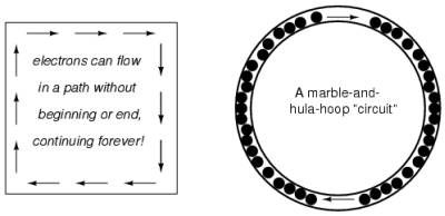 |
A theoretical electrical circuit on the left, and an analogous marble circuit consisting of marbles inside a hula-hoop. | ||||||||||||||||
To summarize: In order to maintain the continuous flow of electrical current through a circuit, the circuit must connect the source (battery (-) terminal) to the destination (electrical device - e.g. light bulb) and back to the source again (battery (+) terminal) in a continuous, unbroken loop of conductor (wire). The "unbroken" property of the conductors in a circuit is known as continuity. If a circuit is unbroken it is said to have continuity. If it is broken, it is said to be an open circuit. You may also frequently hear the term "test the circuit for continuity", which simply means to check that the circuit is unbroken - that it has no intentional breaks (like an open switch), and no unintentional breaks (like a cut wire). Any break in the circuit's continuity, anywhere, regardless of the location of the break will prevent electrons from flowing through it. This can be visualized by returning to the marble analogy. Imagine the "hula-hoop" which the marbles are contained in is cut and the cut ends are capped. Now, the hoop is full of marbles, but because the loop is not continuous, there can be no transfer of motion from one marble to the next as there is nowhere for the marbles to go - they are all just wedged in there. |
|||||||||||||||||
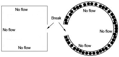 |
Any break in an electrical circuit will prevent electrons from flowing through it; just as any break in the hula-hoop will prevent the marbles from flowing round it. It doesn't matter where the break occurs. Any discontinuity in the circuit will prevent electron flow throughout the entire circuit. |
||||||||||||||||
Now, at this point you might be thinking I've lost my marbles (sorry - couldn't resist!) You may be thinking: "Atoms, marbles, hula-hoops - dude - who cares? - you promised not to drown us in theory". BUT - these simple, basic concepts - once understood - will make understanding the more interesting, practical stuff a WHOLE LOT easier. For example, this concept that:
...is crucial to an understanding of fusing - the where, when, and why of installing fuses in your rig's wiring. And believe me - from my experience, if there's one topic that most people need a lot of work on - it's fusing! VoltageSo, we have a continuous circuit for the electrons to flow - but why do they flow? Well, we need some external force, some imbalance, to make them flow. Conveniently, all things in nature seek balance or equilibrium. To illustrate this, let us return to our shop compressor analogy. If we use a motor to turn a compressor to compress air molecules, they will naturally try to seek out a return to the lower pressure of the surrounding air - this is what makes said compressed air flow through your air hose connected to the compressor and out to the surrounding air, powering your impact wrench or other pneumatic tool along its way. The force is created by an imbalance of air pressure and the air rushing to correct this imbalance is what allows useful work to be done. So it is with electricity, only the force is produced by an imbalance of electric charge. If we have a location or material with a lot of excess electrons, it is said to be negatively charged. If we have another location or material with a deficiency of electrons, it is said to be positively charged. Furthermore, if we connect these two materials with a conductor, electrons will flow through the conductor to balance the charges until both materials are neutrally charged. |
|||||||||||||||||

|
The simplest example of this is one with which we are all familiar - the old shock from static electricity. If you scuff your feet along a carpet you "rub off" some electrons, making the carpet positively charged. If you then touch something like a metal door knob that has a lot of free electrons ready to flow, electrons will rush from the door-knob to the carpet, through you, which you experience as a small electric shock. | ||||||||||||||||
Thus, potential energy stored in the form of an electric charge imbalance and capable of provoking electrons to flow through a conductor is similar to potential energy stored in your compressor's air tank in the form of high-pressure air capable of provoking air flow through a hose. This potential energy is expressed as voltage, which you may think of as "electrical pressure". In the context of electrical power sources, voltage is the amount of potential energy available to move electrons through a conductor. Because voltage is an expression of potential energy, representing the possibility or "potential" for energy release as the electrons move from one point to another, it is always expressed as between two points. Recall the car on the hill, and the potential energy it had was expressed between two points - the top of the hill and the bottom. So it is with electricity and voltage - the potential energy available for moving electrons from one point to another is always expressed as between two points. Of course, voltage can be generated by means other than scuffing your feet on the carpet! Chemical reactions (in batteries) and the influence of magnetism on conductors (as in a generator or alternator) are the two most important in automotive 12V DC. We'll deal with these in some detail later, for now let's just look at how voltage sources can be applied to create electron flow in a circuit. Current Flow in a CircuitLet's take all we've learned so far and examine a very simple, theoretical, circuit. Our theoretical circuit consists of a battery that produces voltage between it's two terminals, and a conductor (wire) connecting the two terminals through which electrons can flow. |
|||||||||||||||||
|
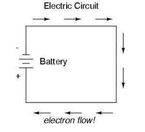
This is a diagram of such a circuit. The battery produces voltage by chemical reaction between the acid and lead plates contained within it. This results in a surplus of electrons at the negative terminal. Since electrons are the the constituent components of electrical charge (and therefore voltage and current flow), and since a long time ago it was decided that electrons are "negative", it is the battery's negative terminal that has a surplus of electrons. Therefore, the electrons flow from the negative terminal of the battery, through the conductor, and back to the battery's positive terminal. |
||||||||||||||||
So long as the battery continues to produce voltage and the continuity of the electrical path isn't broken, electrons will continue to flow in the circuit. This continuous flow of electrons through the circuit in a single, unchanging direction is called Direct Current, or DC. Conventional vs. Electron Flow"Wait just a second!", you may be thinking to yourself at this point. I've just said that the electrons, and therefore electrical current flows from the negative terminal of the battery, through the circuit, and back to the positive terminal. But most of us have been taught and believed for years that electrical current flows from the positive terminal to the negative! The "positive" cable is the "power" cable, and the red one, after all! This is the difference between what's known as "electron flow" notation and "conventional flow" notation. The apparent discrepancy began many years ago with Ben Franklin. Brilliant though he was, Ben actually made an error and assumed electric charge moved in the opposite direction than it actually does.. Now, Ben actually wanted us to think of current as flowing from positive to negative - from surplus to deficiency - as this would logically match with the notion of things naturally moving from high to low - as air moves from high-pressure to low, indeed as a rock rolls downhill from high height to low height. Thus, he called the side that he THOUGHT had the surplus of electrons the "positive" side, and the side he THOUGHT had the deficiency of electrons the "negative" side. By the time the mistake was discovered, the idea of current flowing from positive to negative was so well entrenched (as indeed it is with most of us, me included!) that it couldn't be changed. Unfortunately, Ben was wrong, and had the flow backwards, so that using his now unchangeable labelling, electrons ACTUALLY flow from the negative terminal to the positive terminal. This is known as "electron flow notation" as it is the actual atomic truth of the direction in which electrons flow. I know it seems weird to imagine flipping on you headlights and electrons then rushing from the negative terminal through the ground strap and chassis, then through the light bulb's, switch, and finally back to the positive terminal of the battery but that is in fact precisely what happens. But again, because this seems so counter-intuitive; because we are more comfortable thinking of things flowing from high to low, from (+) to (-); many many branches of science and engineering have chosen to retain the idea of "conventional flow notation" that depicts direct current as flowing from positive to negative. And thus the positive terminal is thought of as the "power" terminal and is red, and the negative terminal is thought of as the "ground" and is black. In the end - for most of us - it's just easier that way. And so, for the rest of this article I will write and illustrate using conventional flow notation (with very few exceptions - and those only when absolutely necessary) - it's just easier that way! ResistanceElectrons move through even the best conductors with some degree of "friction", or opposition to motion. In electricity this opposition to motion is called resistance. The amount of current in a circuit depends on the amount of voltage available to motivate the electrons to flow, and also the amount of resistance in the circuit to oppose that electron flow. Just like voltage, resistance is a quantity that is expressed as between two points . Electrical resistance sounds as if it is an unwelcome thing, and in many cases it can be. But it is also a necessary thing for the electrical current to do useful work. Resistance is roughly analogous to friction in the case of air or water plumbing. Friction in air or water plumbing may be detracting in the pipes and hoses, but is also necessary for the water to power a water-wheel or the air to operate the pneumatic motor in a tool. So it is with electricity - whatever device the electrical current is intended to power - be it a simple light bulb or complex on-board electronics, all such devices provide resistance to the current. The circuit illustrated in the previous section was a theoretical one, and not very practical (or safe!). In fact, it would be quite dangerous to directly connect the terminals of a battery together with a single piece of wire. This is because the wire would offer very little resistance to the current flow, and there would therefore be very little to restrain or resist the unbridled flow of electrons. Such an unrestrained flow of current would be accompanied by the production of massive amounts of heat (it would, in fact, be very much akin to welding - but without control) which in turn would lead to things melting, sparking, spewing molten metal, and burning. Nasty, dangerous stuff and not very practical or useful at all! In fact, such a circuit, where there is very little resistance and consequently an unrestrained surge of current is known as a short circuit or "short". A far safer, and more useful circuit would be one in which a device is powered by the current and also offer resistance to that current.
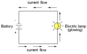
A more practical, far safer, and still very simple circuit would be one in which the battery powers a light bulb. Connected to a battery as a source of voltage, an electric lamp circuit looks something like this: |
|||||||||||||||||
|
As the electrons work their way through the thin metal filament of the lamp, they encounter more opposition to motion than they typically would in a thick piece of wire. The lamp filament has more resistance than the wire. This resistance serves to limit the amount of current through the circuit with a given amount of voltage supplied by the battery. This is quite different from the "short circuit" where we had nothing but a wire joining one end of the voltage source (battery) to the other. |
||||||||||||||||
When electrons move against the opposition of resistance, "friction" is generated. Just like mechanical friction, the friction produced by electrons flowing against a resistance produces heat. The concentrated resistance of a lamp's filament results in a relatively large amount of heat energy. This heat energy is enough to cause the filament to glow white-hot, producing light. And that, dear readers, is our first practical electrical circuit. We'll talk more about practical circuits momentarily, but first let's just recap the most important points thus far: Summary
Ohm's and Joule's LawsOK, so much for the pure theory. We shall now discuss some more practical theory. Yes, it's still theory and yes, there is some (simple) math involved, but it's important stuff. We're not quite ready yet for part numbers and bolting stuff on! Since I can hear the groaning from here, let me just take a moment to explain why I bother with the theory, and why you should bother reading / learning it. While I frequently hear from readers who love the detail, I also recognize that a great many of you are not the biggest fans. In fact, many of you, I know, would prefer to just get straight to the "tell me exactly what to use and how to use it." The trouble is - there's only so many specific, hands-on examples I can give. But what if you are working with something a bit different? What if you find yourself in a situation I haven't described? That's where the theory comes in. With a decent understanding of the theory, you should be able to figure your way through almost anything - whatever your "custom" situation may be. I may not describe a practical example of installing a circuit with six 30-amp devices that you want to connect in parallel using only three normally-open relays - but if you understand the theory you will be able to figure out what size wire you need to use, where to place the fuses, how many switches you need, and what type of relays will be best. So, with you hopefully convinced, let's push on with a bit more practical theory. Ohms law - the relationship between current, voltage, and resistance.We have talked about the relationship between current, voltage, and resistance. Namely that:
But that's only a useful thing to know if we can quantify (measure) these three things and relate them to one another. Indeed we can, and the very simple but powerful equation that relates them is called Ohms Law, named after the German scientist Georg Simon Ohm (OK - so you didn't really need to know his name - I promise to behave from now on!) Here are the symbols and units of measurement for these three most important of electrical quantities:
Ohm's law states that voltage = current multiplied by resistance, or in equation form: V = I * R Using this law, and doing a little algebra, we can re-write the equation so that any time we know two of the three, we can calculate the third. So, we have: V = I * R (voltage = current times resistance) I = V / R (current = voltage divided by resistance) R = V / I (resistance = voltage divided by current). If we return to our air or water plumbing analogies, this law should be fairly intuitive. For example, thinking of water flow in a pipe: flow = pressure divided by resistance. That makes sense. And it's the same as current = voltage divided by resistance. Now, if you're not really keen on algebra (and who could blame you?), you can use the simple diagram called "Ohm's Triangle" to remember the law and help you calculate what you need. |
|||||||||||||||||
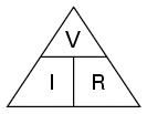 |
First, draw a triangle and arrange the symbols for the three quantities like this. | ||||||||||||||||
|
|||||||||||||||||
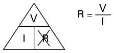 |
Now, simply cross out the value you don't know, and the triangle will illustrate the equation you need to use to find it. In this case, we want to find the resistance so we cross it out, leaving us with the equation R = V / I |
||||||||||||||||
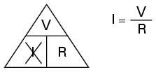 |
Here we wish to calculate current. The triangle tells us we must divide the voltage by the resistance. |
||||||||||||||||
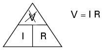 |
And here we want to know the voltage. The triangle tells us we must multiply the current by the resistance. |
||||||||||||||||
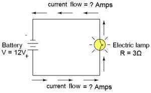 |
So, as an example, suppose we create a circuit consisting of a 12V battery connected to a lamp with a resistance of 3 ohms. What would the current in the circuit be? Easy: I = V /R I = 12V / 3Ω I = 4 Amps. The current would be 4 amps. |
||||||||||||||||
Knowing this we could now decide what size wire we would need to use, which would subsequently tell us what size fuse we would need to use. This would be a practical example of the use of Ohm's Law. |
|||||||||||||||||
Note that the current is the same everywhere in the circuit. The rate of electron flow is the same at every point in the circuit. In this example, we happened to know that the battery was producing 12V and that the lamp offered a resistance of 3 ohms. Of course, we may not always know these things, especially in more complicated circuits. However, with a simple and very inexpensive multimeter we can measure them (the one pictured can be had for less than $5.00!). |
|||||||||||||||||
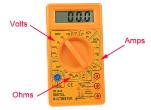 |
A multimeter can be a terribly complicated-looking thing, but in fact, for the simple measurements we are interested in, it is quite simple. The dial is rotated to the correct position for the measurement we wish to take. There are different positions for AC and DC power, so make sure to select the proper DC position. There are different scales for each quantity too. We will most often use 20 DCV (direct-current volts), 10 DCA (direct-current amps), and 200-2000 Ohms on the resistance scale. |
||||||||||||||||
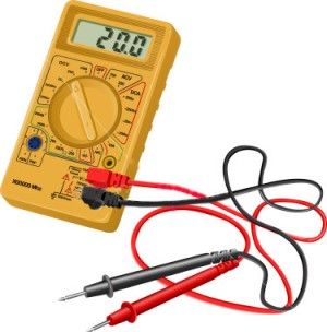 |
Once the dial is set, simply plug in the leads and use the probes to measure the value between the two points. Remember how we harped on about current, voltage, and resistance being valid measurements only when expressed as between two points? This is one of the reasons why. Hopefully you now understand why you don't just stick the probes any-old place - but one on each point between which you wish to measure the voltage, current, or resistance. For example, we could set 20 DCV and put one probe on the positive terminal of the battery and one probe on the negative terminal of the battery and the readout might tell us that there is a voltage of 12.2 volts between the two battery terminals (i.e. that the battery is capable of supplying 12.2 volts of electrical pressure to a circuit). |
||||||||||||||||
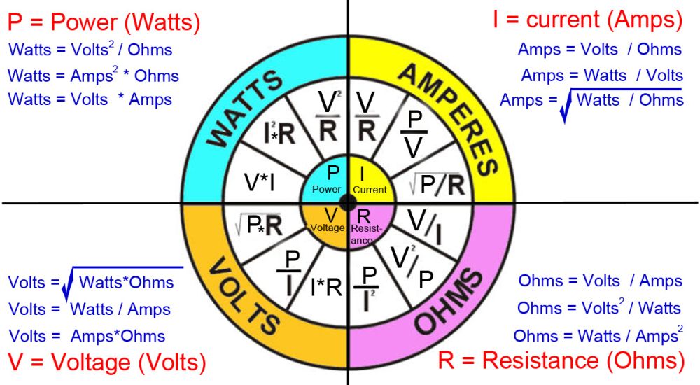
Note that the amp gauge on most multimeters only goes to 10, maximum. If you have really been paying attention you will already know why! OK - so the reason is this. When you connect the multimeter, you are making it part of the circuit, and therefore it will experience the full current that every other part of the circuit does. And recall that current flow causes heat - the more current, the more heat. Since the full current flows through the multimeter, we must limit that current to a value that produces no more heat than the little plastic multimeter can handle. Hence, the 10 amp maximum. For measuring current greater than 10 amps you must use either a specialty, high-current capable meter (expensive!) ... or .... and I have been waiting with some excitement to make this revelation... because you are now an expert in Ohms law, you can measure the values that are easily measured with your multimeter (namely, voltage and resistance), and simply (and safely) calculate the current!! Ta - da! AnalogyTo completely get your head around this Ohm's Law, it may help to return to our air compressor analogy. With our shop compressed-air system we have a compressor (an air pump) that is analogous to the battery - both produce the "pressure". The air pump pushes air around the plumbing (the circuit) against the resistance of the plumbing (chiefly friction). If the resistance to the air flow stays the same and the pump pressure increases, the air flow rate must also increase. If the pressure of the pump stays the same and the resistance to the air flow increases (through a smaller hose, for example) then the flow rate must decrease. If the air flow rate were to stay the same while the resistance to flow decreased, the required pressure from the pump would decrease: PowerOK, so that's all well and good - but it's not really all that practical yet, is it? I mean, it's not as if you can pop into Pep Boys and ask for a shiny new set of offroad lights for your rig that have 3 Ohms of resistance. Well - you could, I suppose, but they're gonna look at you funny if you do! No, to get more practical we must bring POWER into the discussion. At last! Power is the measure of how much work can be done in a given amount of time. Mechanical power is commonly measured (in North America) in horsepower. Electrical power is almost always measured in watts. In electrical terms, power is equal to the current times the voltage. This is easily understood if we apply our compressor analogy again. The amount of work that can be done by our pneumatic tools depends on the power of the compressed air system. The power of the compressed air system is equal to the airflow rate multiplied by the air pressure. That's why to run bigger air tools you need a bigger hose (1/2" instead of 2/8", for example) and/or higher pressure (turn the regulator up to 120psi to run the big impact, for example). In mathematical terms: P = I * V (power equals current multiplied by voltage) In other words - want more power? You need more current and/or higher voltage. P = I * V (power = current times voltage) I = P / V (current = power divided by voltage) V = P / I (voltage = power divided by current). Note that 1 horsepower equals 745.7 watts. Also, as before, instead of doing a bunch of algebra, we can create a simple graphic that contains all we need to know, print it and stick it on the shop or office wall for easy reference. I have seen versions like this one referred to as the "Ohms Law Wheel", but that isn't really fair to James Prescott Joule, as it was he, and not Ohm, who first developed the mathematical relationship between power, current and resistance. In fact, the expression P = I * V is Joule's Law. As such, I just call my version: |
|||||||||||||||||
The Electrical Wheel of Doom!
|
|||||||||||||||||
SummaryThere is a mathematical relationship between voltage, current, and resistance in a circuit called Ohm's Law, which states:
There is a mathematical relationship between power, current, and voltage in a circuit called Joule's Law, which states:
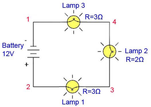
IMPORTANT NOTE on Voltage in Automotive Systems.One thing most of us already know is that automotive electrical systems are 12 Volt DC. BUT - it is important to note that TWELVE volts is just a nominal voltage. Although we always refer to the related circuits and components as "12 Volt", in reality a typical, fully charged automotive battery will produce 12.6 volts (with the engine off) and a car's charging circuit (alternator) will supply 13.2 to 14.4 volts under normal conditions. As such, when using any of the equations we have discussed that include voltage, standard practice is to use 14 Volts, NOT 12. Practical CircuitsYou will no doubt have noticed that we are still a ways from describing truly useful or practical circuits and the components that make them up. Sure, a battery and light bulb connected with a bit of wire make a great grade 4 science project - but it's hardly likely to impress the crowd at the King of the Hammers contingency line! Real, practical circuits are divided into two broad categories - series circuits and parallel circuits. In many textbooks and articles on electricity, this is where they would start showing circuit boards and resistors and such, and begin taking you through complicated arithmetic gymnastics using Ohm's law to calculate precise voltage and resistances. We're not going to do that, as I don't expect most of us will be building our own circuit boards. Instead, I'm just going to cover the basics of the differences between series and parallel circuits and give a couple of practical examples that you may encounter. Series CircuitsThis is a series circuit. The devices (in this case lights) are connected in a row, one after the other, daisy-chain fashion. |
|||||||||||||||||
 |
|||||||||||||||||
Characteristics of a series circuit are:
Mathematically we say:
Using our simple example above:
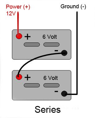
So what does all this mean? Well, what these "rules" tell us is actually quite simple in a practical sense. Test your understanding of what we've discussed so far to see if you can figure out what it is... . . . . . ...OK - here it is. If these were our offroad lights we would actually never want to wire them like this in a series circuit. Why not? Because - recall that power = volts * amps. Also, in a series circuit, each device gets the same current, but the voltage continually drops as we go through the circuit. This means that lamp 2 gets less voltage than lamp 1, and lamp 3 less than 1 & 2. Which means they will not all have the same power and will therefore not be equally bright! Also - the current each gets, while being the same, is not the most it could be, since it is determined by the sum of the resistances, which is obviously more than if each lamp were on its own circuit (or in a parallel circuit). And there's another problem with trying to wire lights in series like this - can you see what it is? The problem is, with many lights, the light's mounting provides the ground, through the chassis, so it would actually be impossible to wire them in series. Which is OK, because by now it should be obvious that we wouldn't want to do this and daisy-chain lights together in series. In fact, there are very few devices in our cars / trucks / buggies we are likely to ever want to daisy-chain together in a series circuit. Indeed, one of the only practical circuits I can think of using devices in series would be two 6 Volt batteries wired in series to provide 12 Volts. That would look like this: |
|||||||||||||||||
 |
|||||||||||||||||
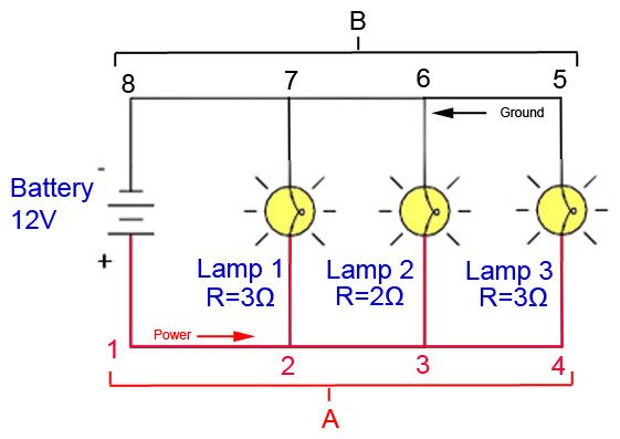
When wiring batteries together in series (positive terminal to negative terminal) the result is the total voltage produced is the sum of the voltages of the individual batteries. In this case, two small 6 Volt batteries are wired in series to produce 12 Volts. You might want to do this if your rig's layout makes it easier or otherwise advantageous (weight balance, for example) to mount two smaller batteries rather than one larger 12V battery. Parallel CircuitsThis is a parallel circuit. In a parallel circuit multiple devices have a common power wire which splits and branches out to supply each device. It helps to imagine these branches lying side-by-side, "parallel" to each other. Most "multiple device" circuits in our rigs (like a row of lights), are wired in parallel. |
|||||||||||||||||
 |
|||||||||||||||||
In a parallel circuit diagram, or "schematic", each individual path (through Lamp 1, Lamp 2, and Lamp 3) is called a branch. A "branch" in a parallel circuit is a path for electric current to flow through one of the devices. In a parallel circuit, all components are connected to common power and ground wires, forming exactly two sets of electrically common points. If you look at the circuit above, the "power" points: 1, 2, 3, & 4 are "electrically common" forming, in effect, one common power point, "A". Similarly, the ground points 5, 6, 7, & 8 are "electrically common", forming, in effect, one common ground point, "B". Characteristics of a parallel circuit are:
These three characteristics are all a result of the defining characteristic of a parallel circuit, which is: there are never more than two sets of electrically common points, no matter how many components are connected; and all components are connected between these two sets of electrically common points. In short - all the devices share a power source and a ground path. The result is: all components share the same voltage; resistance in the circuit is less than resistance in any one branch, and branch currents add together to equal a larger total-circuit current. Mathematically we say:
Using our simple example above:
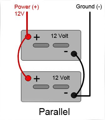
Since most "multiple device" circuits in our rigs are likely to be parallel circuits (for reasons that should be becoming clear now); the practical application of these parallel circuit rules will be important when it comes to things like choosing wire sizes and fuse sizes. We'll get into that in great detail in Part 4, but for now at least you have the background theory to be able to understand the practical rules when we get to them. In addition to our example of a row of offroad lights wired in parallel, another example of a parallel circuit is the wiring of two or more 12 Volt batteries in parallel to increase total battery capacity while retaining 12 Volts (effectively making one big 12V battery). Such a circuit would look like this: |
|||||||||||||||||
 |
|||||||||||||||||
Common Circuit ComponentsSo far we have talked a lot of theory and even our examples of "practical" circuits aren't really very practical, having only wire, a battery, and lamps. Of course, truly practical 12V DC automotive circuits will have more components than this. Here's a list of some of the most common components used in automotive circuits - each of which we will cover in more detail as this series of articles progresses. |
|||||||||||||||||
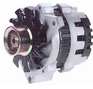 |
Alternator1) Converts engine's mechanical energy into electrical energy. 2) Uses basic laws of electro-magnetics. 3) Available in many different outputs from 30-300 Amps. 4) Takes horsepower to run and produces heat. |
||||||||||||||||
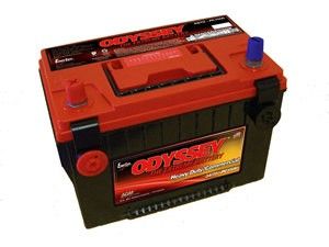 |
Battery1) Converts chemical energy into electrical energy. 2) Stores electrical energy. 3) Rated in Amp-Hours. 4) Batteries in series multiply voltage. 5) Batteries in parallel multiply capacity (amount of current they can supply and/or length of time they can supply a given current). |
||||||||||||||||
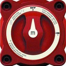 |
Battery Switch1) Used as a master-disconnect to isolate the battery. 2) Can be used on the (+) or (-) side, or both. |
||||||||||||||||
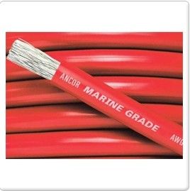 |
Wire1) Provides low-resistance path for current. 2) Protected by insulated coating. 3) Diameter is expressed as gauge. 4) Large gauge = small wire. Small gauge = large wire. 5) The smaller the wire, the less current it can handle before melting the insulation. 6) Solid wire will break when fatigued and can't carry as much current as stranded wire of the same gauge. |
||||||||||||||||
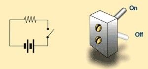 |
Switch1) Mechanical device that interrupts current flow. 2) Used to turn devices ON and OFF. |
||||||||||||||||
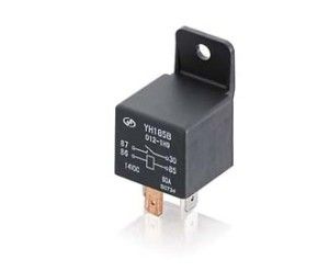 |
Relay1) "Remote control" switch. 2) Used when one circuit is to be turned on by the presence of a voltage provided by another circuit. Can be manually activated (dashboard switch) or automatically activated (turn radio on, amplifier automatically comes on). 3) Allows high-current circuits to be isolated from activation switches. 4) A relay can be triggered with as few as 150 milliamps. The switched output can be as high as 100 amps.
|
||||||||||||||||
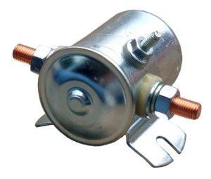 |
Solenoid1) Similar to a relay. 2) Rugged construction for "external" mounting. 3) Often used for high-current, short-duration loads (as in starter motors and winches). 3) Various duty-cycle and current ratings. |
||||||||||||||||
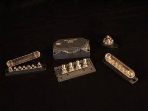 |
Distribution Block1) Used to provide neat, tidy distribution of 12 Volt (+) power. 2) Various configurations available. 3) Can also be used to provide common ground points.
|
||||||||||||||||
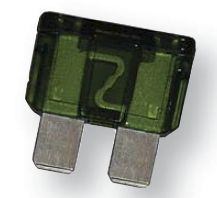 |
Fuses1) Designed to protect the components in a circuit from current overload. 2) Also protects wire in circuits from short-circuit damage. 3) Fuses "blow" at a given amperage, opening the circuit and stopping current flow. 4) Cheap and effective, but must be replaced when blown. |
||||||||||||||||
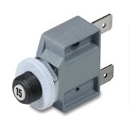 |
Circuit Breakers1) Same function as fuses, but either manually or automatically resettable. 2) Circuit Breakers "trip" at a given amperage, opening the circuit and stopping current flow. 2) More expensive and bulkier than fuses, but needn't be replaced when tripped. |
||||||||||||||||
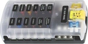 |
Fuse Block1) Provides convenient central location of fuses for multiple circuits. 2) Also functions as a power distribution point. 3) Often provide multiple clean ground points as well. |
||||||||||||||||
 |
Resistor1) Conductive material that impedes current flow. 4) Normally only of interest to folks building circuit boards, but may be used in place of other devices to ensure circuit has enough resistance and doesn't flow excessive current (e.g. in place of a dash-mounted alternator warning light). |
||||||||||||||||
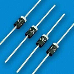 |
Diode1) One-way check-valve of the electrical world. 2) Allows current to flow in one direction only. 3) Light-emitting diode (LED) converts electrical energy into light. 4) Current flows from anode to cathode (think: alphabetical order). |
||||||||||||||||
 |
GroundNot really a component like the others listed, but a vital part of all automotive circuits. 1) Zero voltage reference level. 2) True ground connects to the earth. Hence the name. 3) Circuits we work with are not normally connected to the earth, but to the negative terminal of the battery. Technically this is known as a floating ground. |
||||||||||||||||
|
|||||||||||||||||
|