 |
Disc Braking a GM 14-Bolt Rear Axle By Bill "BillaVista" Ansell |
UPDATE: Be sure to also check out my article: 14-Bolt Disc Brakes V2IntroductionThis article is based on my disc brake conversion for the GM Corp. 14-Bolt (14b) rear axle in my buggy, the Wolf. However, the basic procedures will apply to any rear 1-Ton Full Float axle, with slight variations, which I will attempt to point out. That said - this article is about converting the 14-Bolt, so there may be the odd SNAFU with others that I am not aware of. I have included, where applicable, pictures scanned from the US Military Manual on 14-Bolt maintenance. This will give additional info / diagrams on certain steps in the project, like removing/installing the full-float shafts and setting up the wheel bearings.
|
 |
You will notice that the drums and drum backing plate had been removed from my 14-Bolt some time ago, to save weight and in anticipation of this disc brake conversion. If you are starting with a more or less stock 14-Bolt, the only additional procedures you will have to perform that I did not are:
Even though I didn't need to perform these steps during this project (and subsequently don't have pictures of them either) I shall still describe in the narrative where and when you would complete these steps. Also note - I need no rear parking brake at the wheels, since I use Hydro line locks, and one day will add the T-case mounted parking brake from Jess at High Angle Driveline. As such, I was able to use the regular Chevy 3/4 ton callipers. If you need parking brake capabilities at the wheel, you will need to use different callipers. I understand, but have not personally verified, that the callipers from a 76-78 Cadillac Eldorado will fit the same and have provisions for a mechanically actuated parking brake. The parts list I used is detailed in the first pic below. |
|
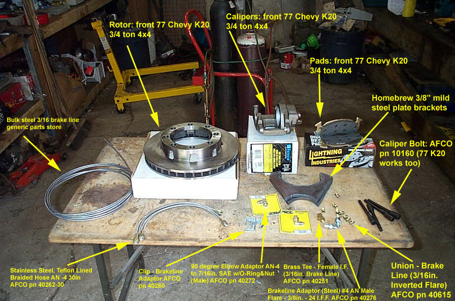 |
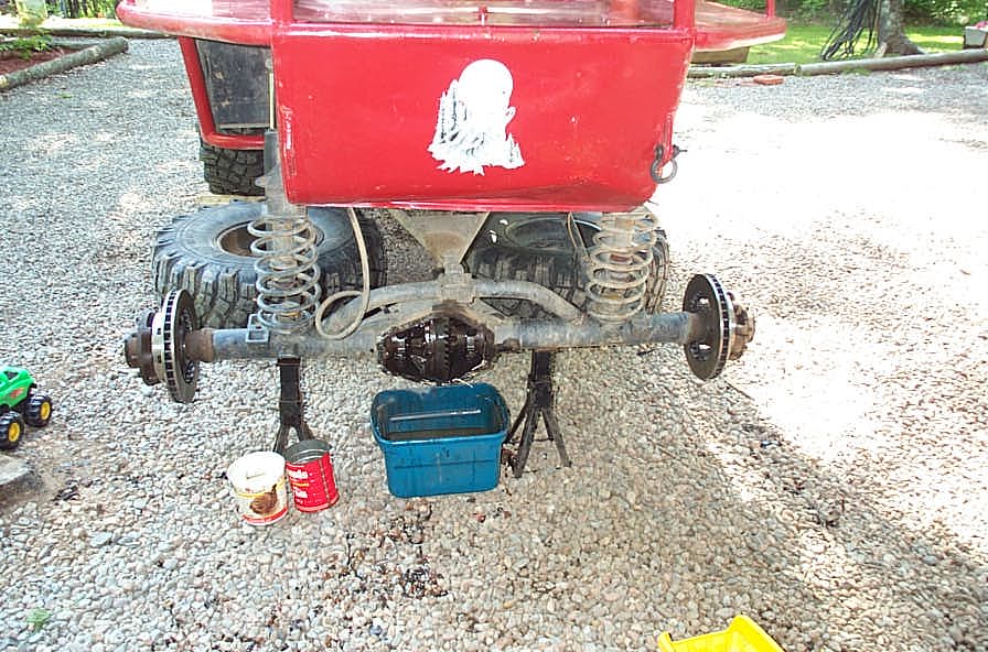
OK gang, the object of the exercise is to get all of this .... (enlarge this pic and have a look - it contains many part descriptions and numbers used) |
||||||
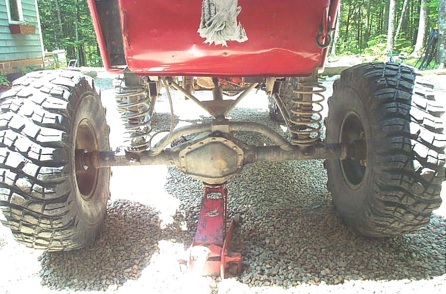 |
...onto here. Hopefully in an afternoon, without breaking anything or teaching the kids any colourful new terms to share with their friends at daycare! | ||||||
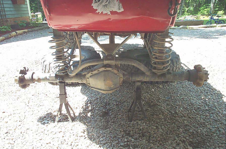 |
Step 1 - Jack it up, support it securely, and remove the wheels. If you need help with this step... get out now while you still can :-) | ||||||
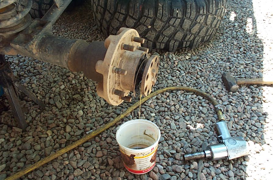 |
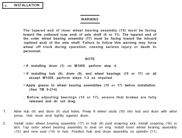
Step 2 - You need to remove the full float axle shafts so you can access the spindle nuts and remove the hubs. Your hubs may still have the large drums attached. The 8 bolts holding the axle shaft onto the hub are 3/4" hex head, and usually pretty tight. I'm spoiled and use an impact wrench. Be sure to place a container under the axle shaft flange to hub interface, as gear oil will spill out when you pull the shaft. When all the bolts and washers are removed, tap (whack?) the flange of the shaft with a large chisel and hammer to knock it loose, then just pull the shaft straight out and set it aside. | ||||||
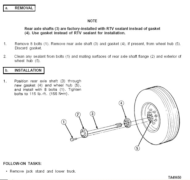 |
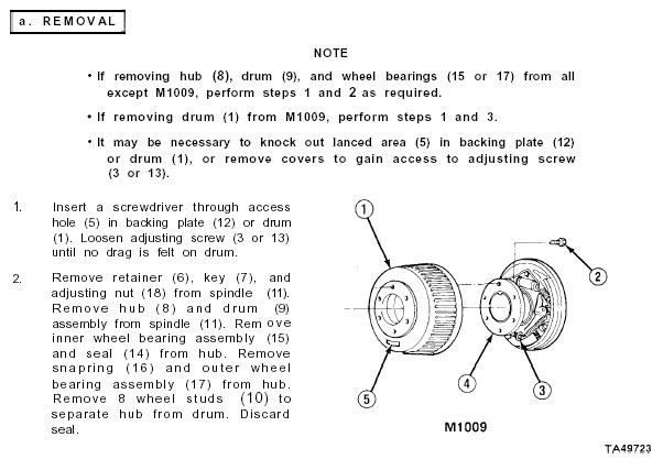
Here's the manual page on removing and re-installing the shafts. Note that the torque on the 8 flange bolts is 115 ft/lbs on reinstallation. | ||||||
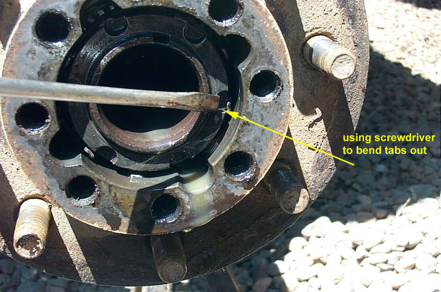 |
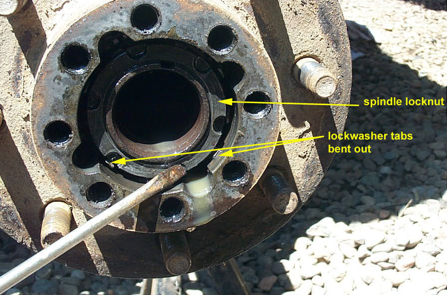
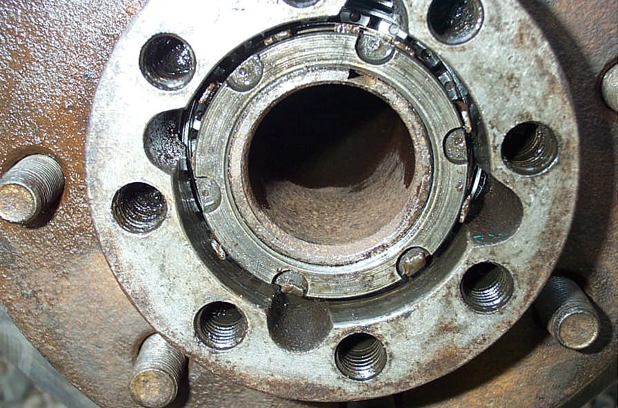
Once you have the shaft pulled, the hub will look like this. Bend the little tabs on the spindle lock-washer outwards so the outer spindle lock nut can be removed. | ||||||
 |
The proper way to remove and install the spindle nuts is to use the proper 6-slot socket. Of course, if you're a high-tech redneck like me, you can bang them out with a hammer and screwdriver! Note - there are a huge number of different lock washer and spindle nut arrangements out there. Some are 6 slot as shown some are 4 slot, some are a large hex head and some are a special rounded hex head. Also, some lock washers use tabs as shown, and some have holes that index onto little "tits" on the spindle nuts. You will have to adapt, improvise, overcome. |
||||||
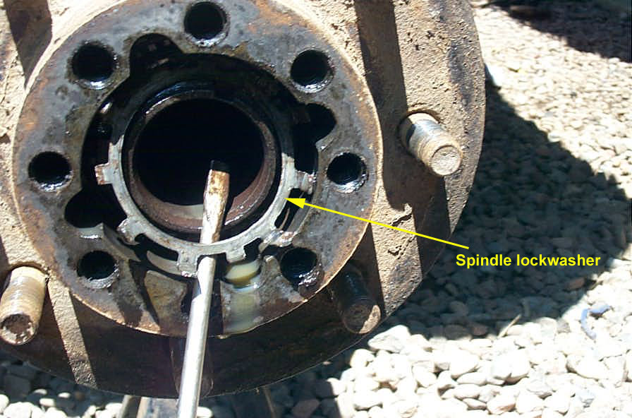 |
Once the outer lock nut is removed, fish out the lock washer with a screwdriver / pick. | ||||||
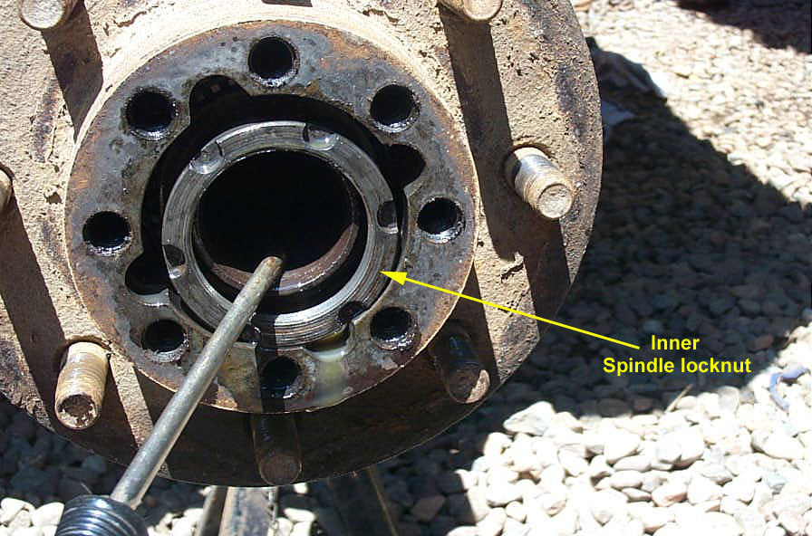 |
And then the inner nut can be removed. | ||||||
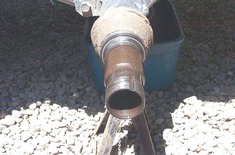 |
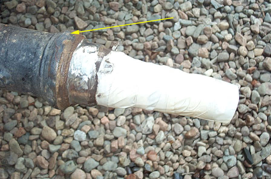
Next, you grasp the hub firmly, and pull it off the spindle. Careful! - If it still has the drums on, it will be very heavy. Use caution to avoid dropping the inner spindle flat washer and outer wheel bearing cone as the assembly pops off the spindle. Turn it outside pointing up, as the hub seal will keep the inner wheel bearing from falling out. Afterwards, this is what the bare spindle looks like (hopefully your isn't as beat as mine - it's had a hard life!) Of course, you may well have the drum brake backing plate still attached at this stage. If you do, unbolt it now and set it aside / throw it away. |
||||||
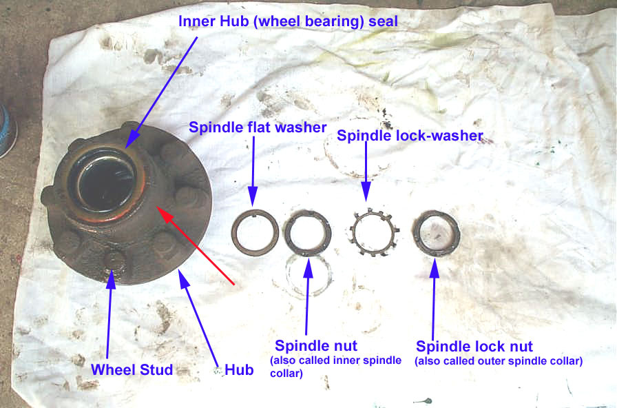 |
Here's the back of the hub, and all the spindle washers and nuts laid out from left to right in the order they go back on. In other words, the washer on the left goes in first after the hub is placed back on the spindle. Here's the first important note on different full float (FF) rear axles. The Outside Diameter (OD) of the back side of the hub (indicated by the red arrow in the pic) are different on different axles. I know that on a Dana 70, this OD is just about an 1/8" too big to fit through hole on the rotor most commonly used (1977 Chevy K20 4x4 front rotor). Most people just machine it down. You can do this the brutal homebrew way with a hand grinder, as this hub/rotor interface is not a machined fit, the lugs keep the hub and rotor together concentrically (true). |
||||||
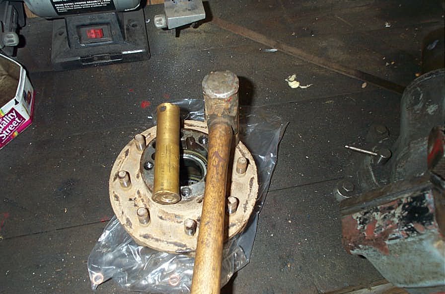 |
Once the hubs are removed you need to separate the drums from the hubs and discard the drums. Do this by pressing out the 8 wheel studs with a big hammer and a soft brass drift. In my case, the drums were long since gone, so all I had to do was press out the wheel studs in preparation for attaching the rotor to the hub. |
||||||
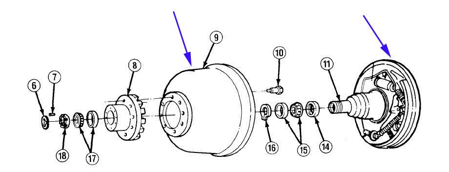 |
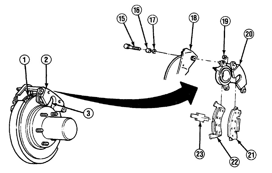
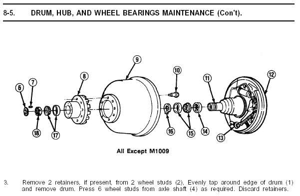
Here is a good picture showing the entire hub and drum exploded view. The 2 pieces (brake drums and brake backing plates) you will be removing are indicated by the blue arrows. | ||||||
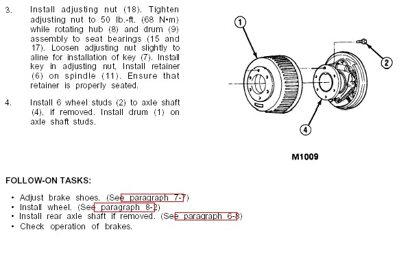
| I went ahead and changed all the wheel bearings and races at this time, since I had the hubs off anyway. The manual pages here show how. You can also see my pics and description of the process in my 14-Bolt bible article (coming soon!) But since this isn't strictly required in converting to disc brakes, I have not taken the time to describe it here in detail.
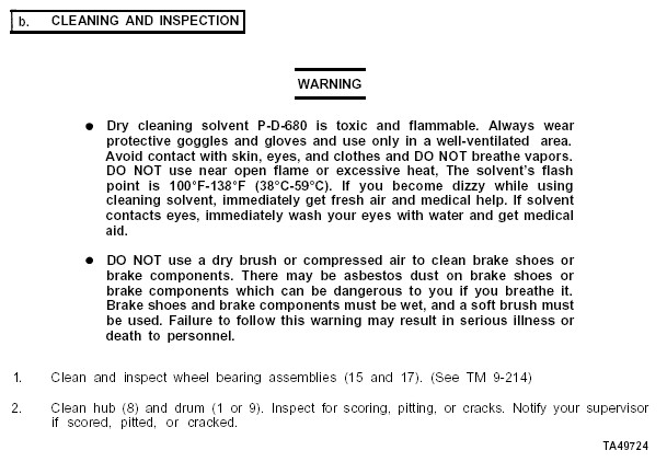
Below are the manual pages covering removal and installation of the hubs, as well as removal, inspection, replacement, reinstallation, and adjustment of the wheel bearings. |
|||||||
|
|||||||
 |
The next step is to install the rotors onto the back of the hub, and securely attach the two together by staking them together with the wheel studs. I used the same hammer and brass drift method to drive the studs back in. The observant amongst you will note that the picture to the left shows a rotor and hub staked together with new, longer-than-stock wheel studs - this picture was sent to me by reader Dale Young and is used with his kind permission as I had installed mine back on the axle before taking a suitable picture to show this step. For a complete discussion on wheel stud options - see my article: 14-Bolt Disc Brakes V2 |
||||||
 |
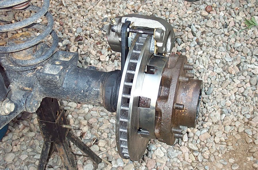
Once you have the hubs and rotors assembled, place them back on the axle in preparation for marking where the calliper brackets will be installed. There's no need to install the lock washer and outer locknut, but you should install the flat washer and the inner spindle nut and set the bearing preload properly. Use the manual pages above, or the 14-Bolt bible(coming soon!), as a guide if you are unsure how. | ||||||
 |
Hub and rotor installed on axle for test-fit and marking of calliper brackets . I would be remiss if I didn't mention the fact that the stock 14-Bolt wheel studs have a large round head that doesn't fit quite right into the small bore designed for the stud head in the 3/4 ton rotor. The solution is to source new studs that do. I am cheap, lazy, and only ever drive this rig offroad at a crawl, so I simply re-used my studs for now. Eventually, I will replace them, as the net result of re-using them is that the lug nuts only just fully engage the threads on the stud, with no "stickout" of the stud, and this is certainly not ideal. When I figure out all the details on the stud dimensions and part numbers, I will add the info to this article. |
||||||
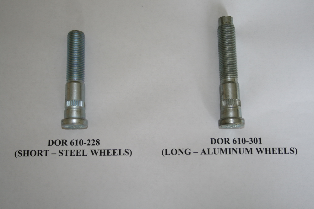 |
UPDATE: Here are pics and part numbers of the studs recommended by reader Joe DeLano for use in the 14-Bolt disc brake conversion. They are:
For a complete discussion on wheel stud options - see my article: 14-Bolt Disc Brakes V2 |
||||||
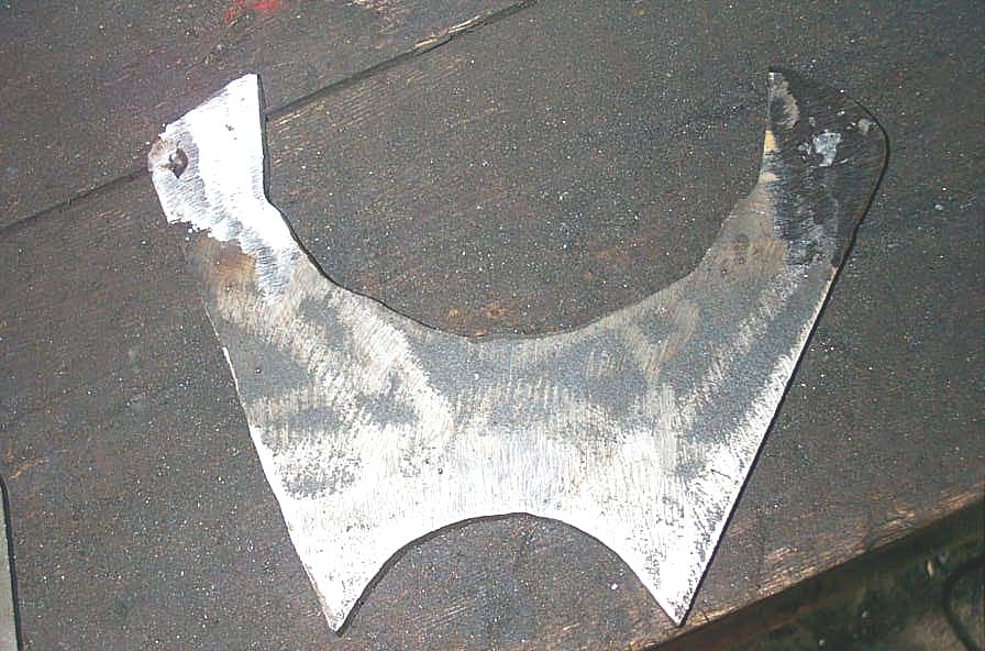 |
I made my own calliper brackets from 3/8" mild steel plate. Two pieces 8"x8" is sufficient to cut 2 brackets. I based my brackets on AFCO Racing part number 40120-1, which they describe as " Calliper Bracket Rear - GM - 3 1/2in. Radius". Nobody would mistake them for art, that's for darn sure! Depending on your axle (and its radius), many folks have reported success with the brackets from A&A Manufacturing. Be warned though, that you may need to customize / modify the brackets to make them taller, because the A&A and AFCO brackets are all designed for stock cars, which do not use a rotor as large in diameter as the 3/4 ton truck rotor. |
||||||
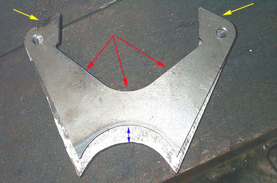 |
The AFCO bracket has the correct hole spacing for the calliper slide bolts (the distance between the centre of the holes is exactly 71/16", and the holes are tapped to 7/16-NC14), and the correct 3.5" tube radius for the 14-Bolt, but it is not a direct fit. The "throat" area needs to be opened up a bit to fit around the 3/4 ton chevy callipers (area indicated by red arrows), and most significantly, it is not the right "height" between the radius and the calliper bolt holes. It needs to be 1/2" taller, so that the calliper clears the large diameter 3/4 ton Chevy front rotor. The blue arrow indicates where it has to be taller. If you were to use it as is, the calliper bolts would hit the rotor id before the radius of the bracket was anywhere near the axle tube. Of course, I did not know this BEFORE I purchased them, and since they were cheap, and a pita to return, I simply tack welded them to my homebrew brackets (yellow arrows) to help guide me in drilling and tapping the holes for calliper slide bolts. |
||||||
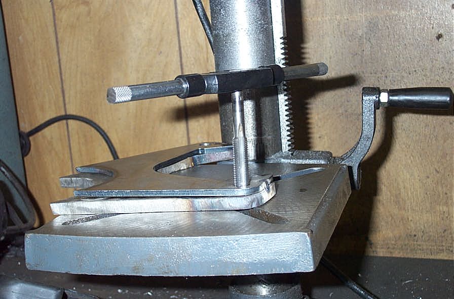 |
Here I am drilling and tapping the holes, guided by the AFCO bracket. Machinist I am NOT! :-) |
||||||
 |
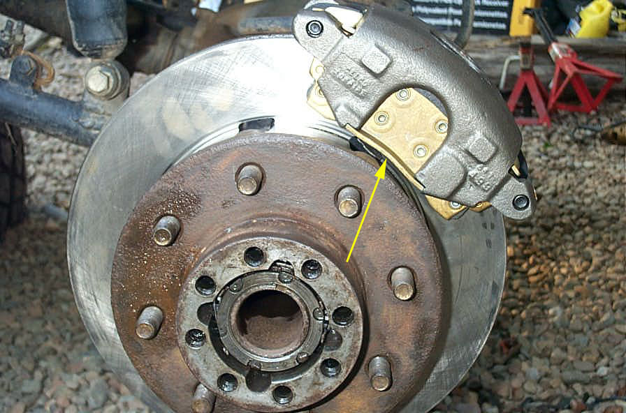
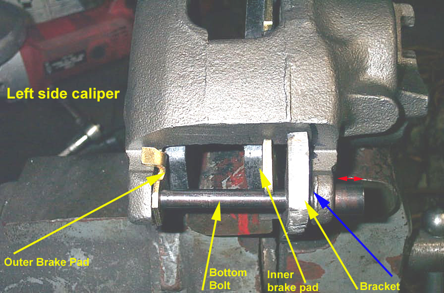
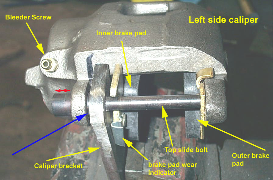
Once you have the brackets all cut out, drilled, and tapped; you assemble the brake pads into the calliper, then bolt the loaded calliper to the bracket. If you are unsure of how this works with the 3/4 ton Chevy brakes, the picture at the left shows the orientation of the parts. The following 3 pics below also show the brake assembly in detail. | ||||||
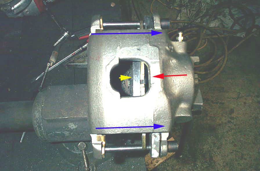 |
Before you take the bracket and calliper assembly to the axle for test fit and marking for welding, it is important that you have the calliper properly oriented on the slide bolts, so that you get maximum possible calliper movement, and therefore the best possible accommodation for wear in the brake pads while still achieving full braking. This pic shows the forces and movements when the brakes are applied. Keep in mind it is the left rear calliper, and would be installed on the axle in the orientation shown with the bleeder screw inboard of the rotor, and at the top. When the brakes are applied, the piston is forced out of its bore in the direction of the red arrow. The inner pad is thus forced against the rotor. As the rotor is immovable laterally (held in place on the spindle by the spindle nuts and bearings, and is incapable of sliding back and forth laterally on the spindle), the rotor "pushes back" at the yellow arrow. The net result is, that as the brakes are applied, the calliper will slide on its bolts in the direction of the blue arrows, until all clearances are taken up. |
||||||
 |
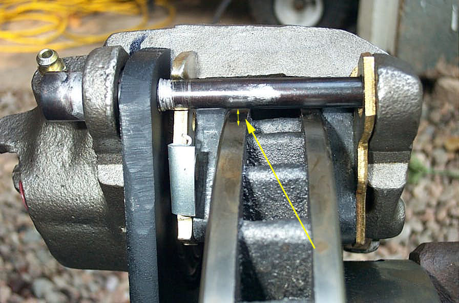
This close-up of the above pic, shows the proper bolt / bracket / calliper orientation for initial installation. Because the calliper slides to the right (on the left side), most of the slide portion of the bolt should be to the right, sticking out of the calliper (red arrow) and the gap between the inner calliper mounting holes and the calliper bracket (blue arrow) should be minimal. | ||||||
 |
This pic shows the same thing from the top of the left hand calliper. Once you have the unit correctly assembled and aligned like this, you're ready to slap it on the axle to test-fit and mark where the bracket is to be welded on. |
||||||
|
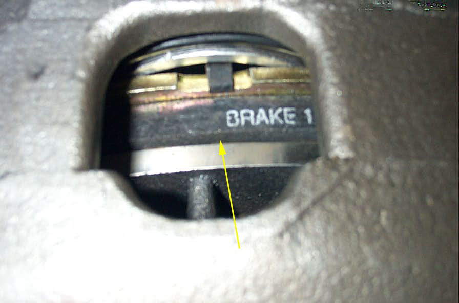
Place the calliper over the rotor, and rotate to the desired position. I chose as high as possible on the rotor (about the 1'o'clock position) for clearance from the rocks, while still maintaining the bleeder screw reasonably close to being at the top for easier brake bleeding. You can of course mount the calliper right on top of the rotor at the 12 o'clock position, but that would mean it has to be dismounted for bleeding. Once this positing is established, before you mark where the calliper bracket will be welded on, you should check 3 important clearances. ONE - as shown at left - check inside of brake pad to rotor hat OD clearance (yellow arrow). |
||||||
 |
TWO - check for clearance between the calliper slide bolts and the OD of the rotor (yellow arrow). | ||||||
 |
FINALLY - check the OD of the rotor to the OD of the brake pad match up. In my case, you can see I made the calliper bracket just a hair too tall, and the pad stands proud of the rotor just a bit. Not enough for me to redo the brackets, and certainly much better a hair off in this direction, rather than the other! Now it's time to mark where on the axle tube (actually, on the spindle in this case) the calliper bracket will be welded. Just approximately will do, it's just for cleaning purposes at this point. |
||||||
 |
When that's done, remove the complete bracket/calliper/rotor/hub assembly, and clean / grind the area of the spindle where you will be welding on the calliper brackets. You can also remove the drum brake backing plate flange from the axle by cutting or grinding it off at this point if you desire. Mine has long gone (yellow arrow). During grinding I attempted to protect the spindle with tape. Once the spindle is clean, reinstall and check everything as above. If it all looks good, go ahead and tack weld the bracket in place. Then, do a final clearance check, and then remove the calliper and pads, rotor, and hub, in preparation for the finish welding. |
||||||
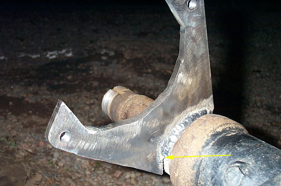 |
Protect the spindle with some anti-splatter or other protective covering, and weld on the calliper brackets. This is where proper fit-up comes into play. You can see where the weld got a little hairy once the gap between bracket and spindle started to get a little large. |
||||||
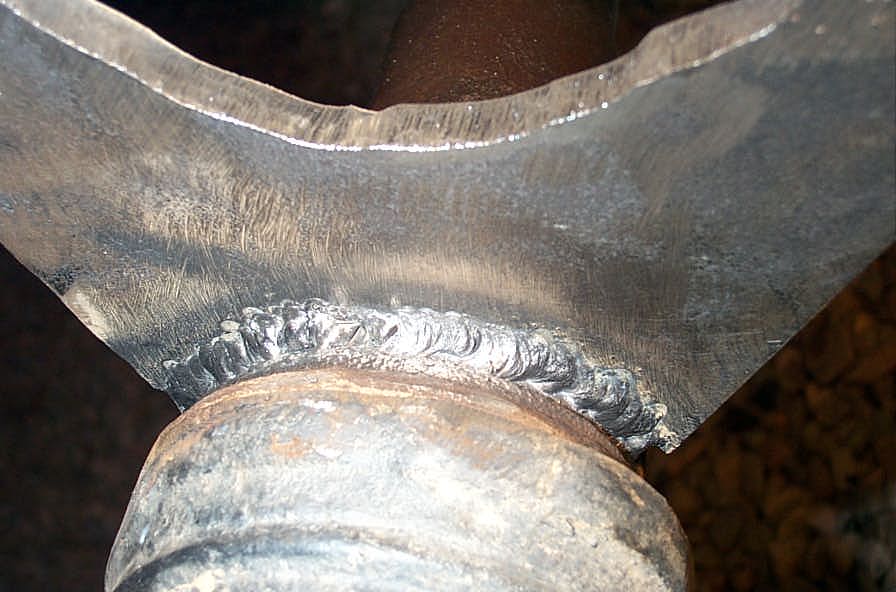 |
Mind you, nobody's any more likely to confuse me with a professional welder than they are to confuse me with a machinist (or ballet dancer, for that matter). Still - I don't think the bracket will be flopping off anytime soon. |
||||||
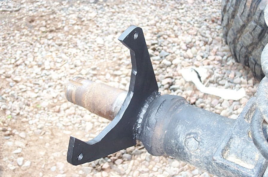 |
And it looks OK once it has cooled, been painted, and dried! When that's done, install the hub and rotor, adjust the wheel bearings, and install the calliper and pads, then all that's left is the plumbing. |
||||||
 |
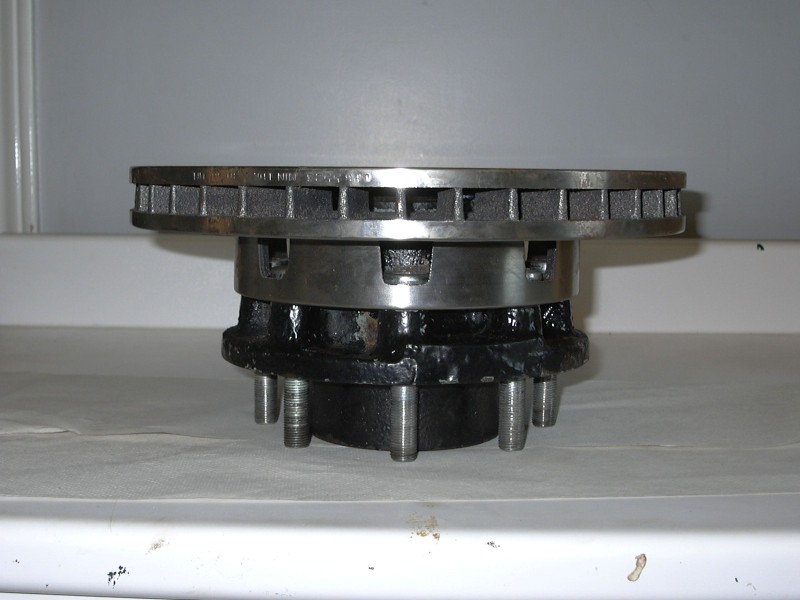
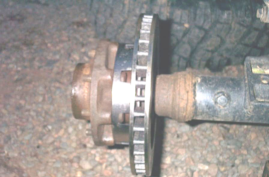
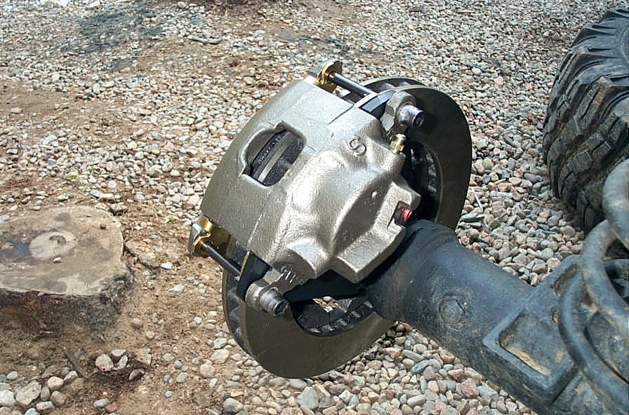
If you install the hub correctly (use the manual pages above and/or reverse the removal procedure), in the end it should look like this. | ||||||
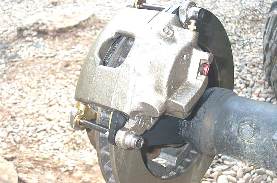
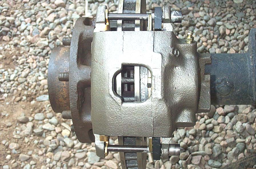
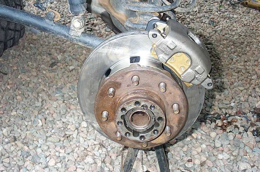
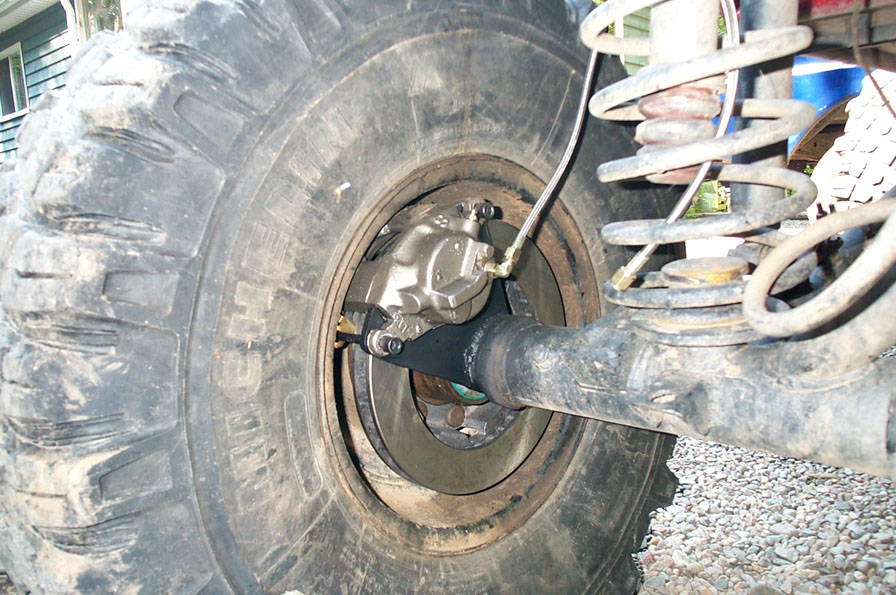
| And these pics below show what the finished disk brakes look like. | |||||||
|
|||||||
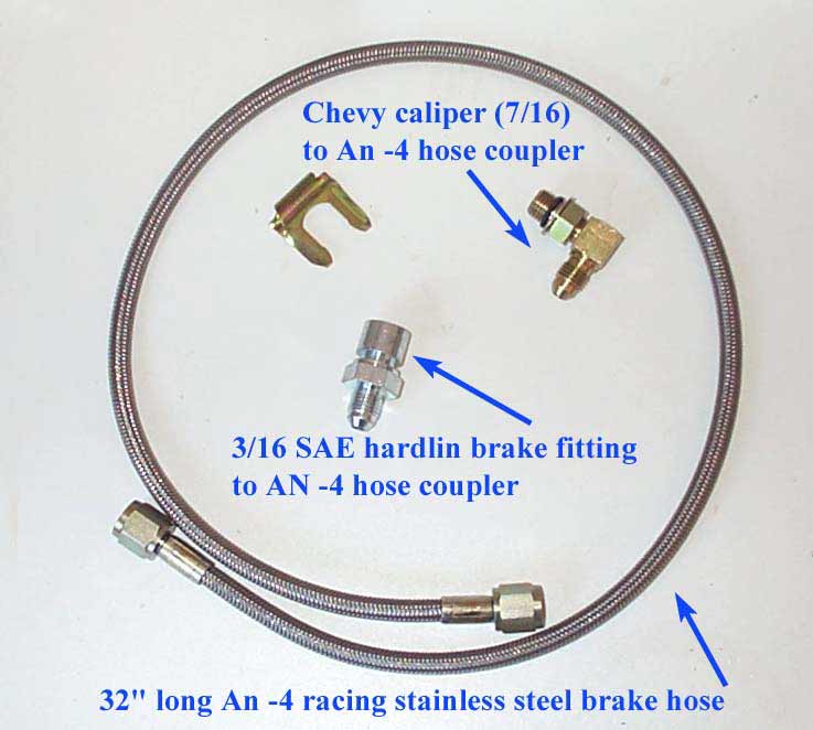
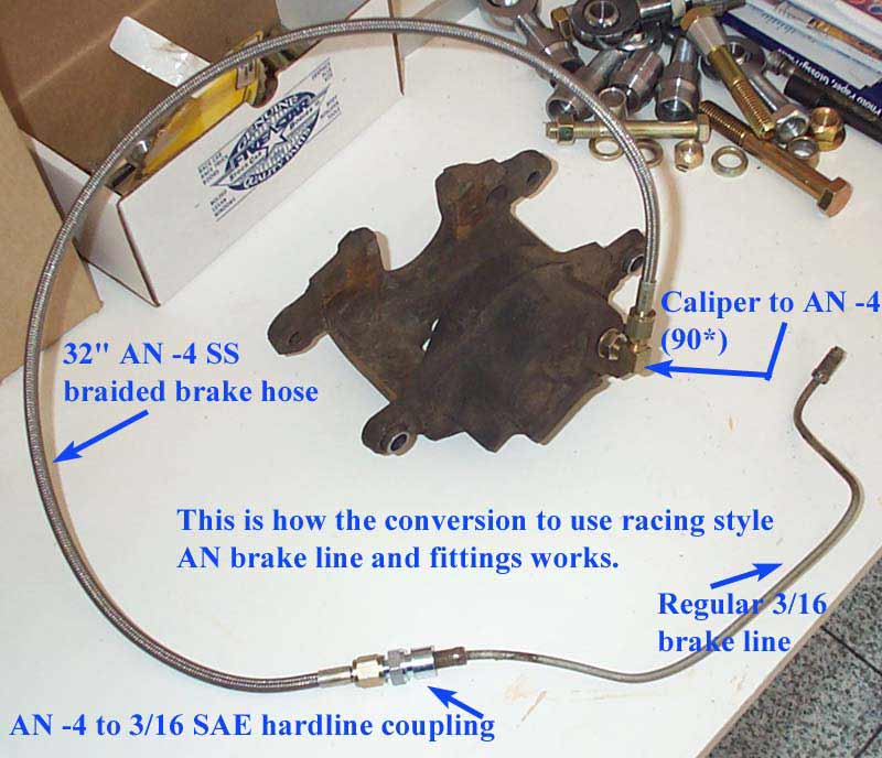
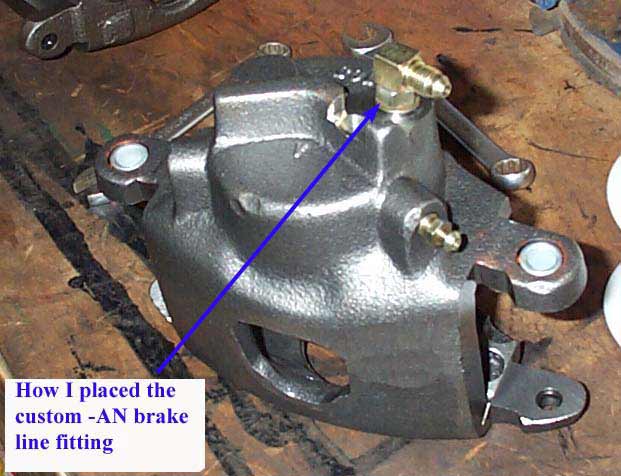
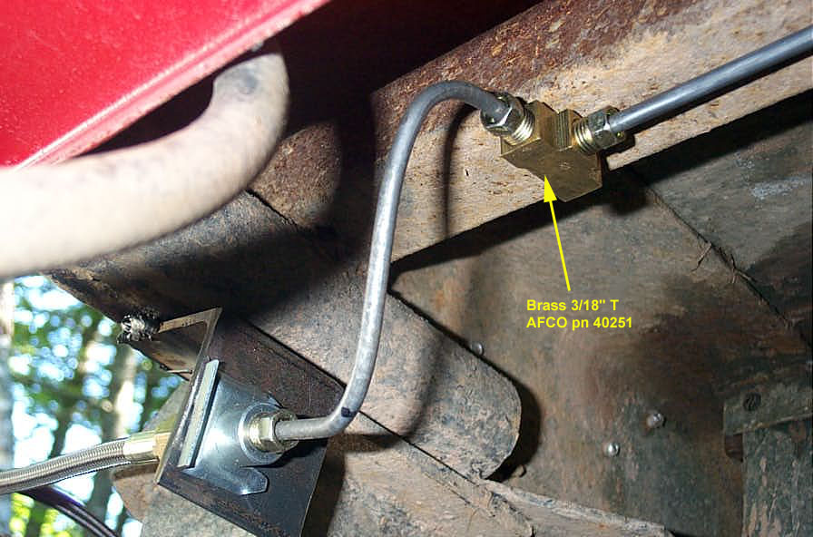
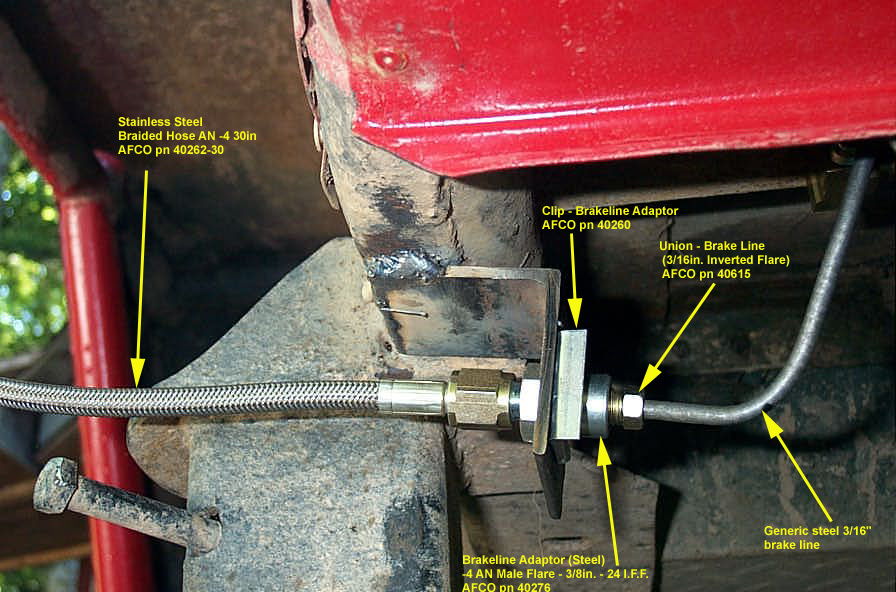
Since I had no rear brakes previously, and therefore no rear brake plumbing, I had carte blanche when it came to plumbing the rear. You may have to work around your existing system, or you may decide to rip it all out and start over as I did. I chose my old favourite, AN -4 lines and adapters / fittings from AFCO Racing combined with standard steel 3/16" brake line. The following pics show the details of the plumbing, and the part numbers. It's pretty self-explanatory, and I won't go into great detail as almost certainly everyone's plumbing setup will vary quite a bit. |
|||||||
|
|||||||
Of course, now that the simple stuff is complete, the real work on a rear disc brake project begins - and that is understanding and building the systems valving - including taking into account master cylinders, pedal ratios, combination valves, residual valves, hold-off valves, proportioning valves, piston ratios, etc. etc. But....all that's the subject for another separate, and very loooong article. You can check it out in the Brake Bible. UPDATE: Be sure to check out my article: 14-Bolt Disc Brakes V2 |
|||||||
|