 |
Axleshaft Tech By Bill "BillaVista" Ansell |
IntroductionDeceptively simple in appearance, modern axle shaft technology is actually quite technical and complicated. I certainly do not poses all the answers; neither, on the other hand, does any other single person as far as I can tell. In this part of the BillaVista-60 article I will share with you everything I have learned about alloy axles, shaft technology, and splines. Hopefully this will help to explain and illuminate why I decided to build my axle using Superior Alloy Axle shafts, and allow you to make your own product evaluations and purchasing decisions from an educated, or at least informed, point of view. |
 |
That said - there are no inarguable absolute truths in the world of axle shaft technology. Major manufacturers and many talented professional engineers often have serious disagreements on the topic. One of the reasons for this, especially in our case (dealing with 4x4 front axles) is that, as a sport, rock crawling is still really in its infancy - meaning there hasn't yet been time for the generations of investment in product R&D that there has in more established motorsports - none of which use front 4x4 axle shafts! Also, as the rock crawling market is young and growing rapidly, competition is fierce leaving companies and engineers even more tight lipped than their drag racing colleagues. My purpose is to try and establish just what makes a great axle shaft, and what qualifies a product as "the best". In order to do so, we must have some background knowledge of axle shafts and their design. But where are we to gain this knowledge? One could of course ask the manufacturers themselves, but we can be reasonably certain they would assure us that theirs are the best! So, in addition to asking the manufacturers it seems to me there are 3 main sources of information to which we can turn:
Regarding the first source, consider that the technology involved in front axle shaft design is different than for rear axles; not nearly as much is known or proven in front axle technology as in rear, and those that do know, aren't saying much. Keep in mind that when discussing (or arguing :-) front axle technology, it is not possible to simply refer to what is done with drag racing or other rear axles, as the technology can be quite different - though there are similarities and basic principles we can learn from. Regarding the second source, the OEMs (even if it is only the source from which we extrapolate) are also of limited use to us in navigating the waters of front axle tech because of one simple law, and that law is: "All design is a compromise" This fact, coupled with the requirement for OEM's to generate profit for shareholders as their single goal of overwhelming primacy means they design not the "best" or "strongest' products they can, but those that are "adequate for the job, in the shortest time possible, at the cheapest cost" Those are the practical limitations of real-life engineering - they don't have the luxury of designing "ultimate" products. To be sure, they know a great deal about axles, and we can learn from them - but we must temper what we learn with the knowledge that their goals are very different from ours. Which leaves us with the final source - basic engineering principles. Of course, because I am not a professional engineer - I am limited in my ability to apply engineering principles - though I think I can do it well enough to at least be an informed consumer. I will share with you what I know of these principles and how I used them to determine who had the best shafts for the BillaVista-60 - but keep in mind that I am not a pro - just an average Joe. In the end, the data I have gathered over the last 3-4 years comes from many and varied sources - from:
After all that, the only thing I know for sure is that I don't know everything - not by a long, shot. But I have learned quite a lot, certainly enough to be a well informed consumer. In my front axle I want the strongest axle shaft available. By strongest I mean able to handle the largest torsional load - which is the technical way of saying I want my axle shafts to be able to handle big tires, reasonable horsepower, and hard use in the rocks - steep climbs, axle bouncing, alternately slipping and grabbing, tires wedges amongst rocks - the works, serious abuse! For all things load bearing, strength comes in 3 kinds: Strength of Material (including treatment and process); Strength of Size (bigger is stronger - no surprise there); and Strength of Shape (profile of the shaft) More specifically for axle shafts, there are three components that go together to make a great front axle shaft. They are:
We will look at all 3 in turn. Material and TreatmentRecall some basic facts from my Steel & Materials Strength Article:
All of these factors are important in the manufacture, or in our case selection, of an axle shaft. Depending on the desired properties of the shaft, different material and methods will be used to make them. Plain carbon steel shafts, like those used by the OEMs and many aftermarket suppliers cannot be through hardened. Examples of non-through hardenable steels used to make axle shafts include SAE 1055, 1541, etc. Similarly, true alloy steels used to make axle shafts (e.g. 4340, 300m, etc.) must be through hardened to reap the benefits of the alloy's strength. As a result, all 4x4 front axle shafts fall into one of 2 broad categories in terms of their material and treatment. They are either: - Carbon steel / induction hardened; or - Alloy Steel / through hardened. Heat TreatmentSo what are the different hardening methods? Induction hardening is done by placing the metal part inside or close to an "applicator" coil of one or more turns, through which alternating current is passed. The coil, formed to suit the general class of work to be heated, is usually made of copper tubing through which water is passed to prevent overheating of the coil itself. In most cases, the work piece is held either in a fixed position or is rotated slowly within or close to the applicator coil. Where the length of work is too great to permit heating in a fixed position, progressive heating may be employed. Thus, a rod or tube of steel (e.g. an axle shaft) may be fed through an applicator coil of one or more turns so that the heating zone travels progressively along the entire length of the work piece.[1] In the case of axle shafts, the shaft is passed through the coil, and the coil has to be of a small enough diameter so that it is close enough to the shaft to do the heating. Unfortunately the small diameter of the coil prevents the passage of the yoke (or flange in a rear axle), which means induction hardened front axle shafts do not have hardened yokes. This is, of course, a MAJOR weak point, as it is very often the thin, soft yokes that are the weakest part of a front shaft and therefore the first part to fail. Induction hardening will be done to a certain hardness level, and do a certain depth from the surface, called the "case depth". Typically induction hardening penetrates to about 0.150-inch and the axle core remains relatively soft. Typically, the shaft surface hardness is a very hard 55-58 Rockwell (almost brittle). There are some benefits to induction hardening, even over through hardening. The exact physical and chemical metallurgy is beyond the scope of this article, but basically the induction hardening process leaves the shaft so hard at the surface, that there is a residual compressive stress at the surface (using our Lego block analogy from Part 1a, imagine the surface Lego blocks being pressed down on, making them harder to bend apart). This residual compressive stress actually improves fatigue resistance and prolongs fatigue life. Why? Because most fatigue cracks initiate at imperfections at the surface of the shaft (scuffs, nicks, burrs, rust, corrosion, grinding marks, etc) and grow from there. The residual compressive stress makes crack tip advance under cyclic loading more difficult. Note also that other surface treatments help to prevent crack propagation, from finish grinding and polishing to paint or other coating application. Through hardening, though in reality very technical, is much easier to describe. Essentially the entire part is placed in a large (but very special) oven-like machine and then heated up, and held at a certain temperature. The part is then the cooled at very specific and carefully controlled rate. The result is, the entire part is hardened, including the yokes, AND the part is hardened THROUGH it's entire thickness, hence the name - through hardening. Through hardening produces a part with a much more even and uniform crystal lattice structure (grain), and therefore with much improved mechanical properties - notably yield and ultimate strengths. Take for example, 4340 Chrom-moly steel, In its normalized state (having a hardness of Rockwell C 22) is has an approximate Ultimate Tensile Strength (UTS) of 112, 000 psi. However, through hardened to a hardness of Rockwell C 42 it has a UTS of approximately 181,000 psi! |
|
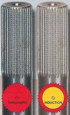 |
Picture graphically illustrating difference between through hardening and induction hardening. Pic from Strange Engineering ad. |
||||||||||||||||||||||||||||||||||||||||||||||||||||||||||||||||||||||||||||||||||||||||||||||||||
Clearly, through hardening an axle shaft makes it vastly stronger and therefore through hardening is a must for any shaft to be considered for the title of "ultimate." Of course, the ideal treatment would be a combination of through hardening and induction hardening, to take advantage of the best of both worlds. There is one manufacturer who does this, and ONLY one in the 4x4 axle shaft aftermarket that does. The answer should come as no surprise - Superior Axle and Gear! MaterialBut what about the difference in just the material itself? Compare 2 typical steels used to build axle shafts, one representative of each group:
UTS in psi
Notes:
Regardless of the steel's condition we can clearly see that the cr-mo steel has much greater tensile strength. Recall from part 1 this is due to the addition of the alloying elements themselves - the chromium and molybdenum. Therefore, manufacturing axle shafts from an alloy steel, though much more difficult, time consuming, and expensive, gives us the double-advantage of greater strength because of the material itself AND grater strength because of the through hardening possible. So what does all this mean to the shaft? It's NOT what most people think! The little known FACT is, the material and how it is heat treated have NOTHING to do with how much the axle will twist under a given load. How much an axle will twist is determined by the torsional modulus of elasticity of the axle, which as you will recall from part 1 is a constant for all steels. This means that all axles, of the same size and profile (shape), under the same load will twist exactly the same amount. If you were to take identical Spicer OEM (SAE 1055), Moser (1541M), Dutchman (1541H), and Superior (4340) axles and chuck them in a torsional testing machine and apply the same load, you would see them all twist exactly the same amount. The difference is: depending on what steel or alloy they are made from, they will behave differently when that load is released. Recall the stress/strain diagrams and properties from Part 1a - The different steels and alloys have different mechanical properties and therefore stress/strain curves. the "better" alloy steels will have a much greater 'elastic range" and much greater yield strengths, meaning they will spring back unharmed to original size and shape where the lesser steels may not. Lets' say, for the sake of argument that we we put 120,000 psi load on the axle shaft (say, by wedging a tire and tromping the gas) - Regardless of the axle material they will all twist the same amount, however, the one made from 1030 carbon steel will have had its Ultimate Strength exceeded, and so will break. The one made from 1541 may only have had its yield strength exceeded and so will not rupture but will not return exactly to it's original shape - it will have twisted or taken a permanent set. The alloy axle made from 4340 will have had neither its ultimate strength nor its yield strength exceeded, and so will return to exact original size and shape - in effect shrugging off the load an carrying on unharmed. In short, the "better" axles made from alloy steel and through hardened are "stronger" not because they resist twisting more or twist less under load, but because they are made from a material and process that allows them to handle the twisting better, to survive it unscathed. That's what being built for the task is all about, and THAT is what makes the best 4x4 shaft! For those mathematically inclined, the equation for how much a solid steel shaft will twist under load is: alpha=[584(T)(l) ] / D^4 * G Where: alpha = the torsional deflection
in degrees (how much it twists) Note that in the equation, the diameter of the shaft (D) is raised to the power of 4. This shows mathematically why a larger shaft is "stronger" than a smaller one, because it twists less (resists the load better or has a steeper stress/strain curve). Note that this "stronger" - strength of size - is quite different from the "stronger" attributable to material and treatment. SummaryStrength of size - larger shaft is stronger because it resists the load better (twists less under load) Strength of material - Shafts made of better material and process (alloy shafts, through hardened) are stronger because they can take much larger loads before yield and rupture. They "shrug off" applied loads much better. Both play a part in determining how much load a shaft can take, and therefore when it will fail, and therefore how suitable it is for our intended use. However, you begin to see how difficult it is to just label something as "stronger". Ideally, for the shaft to be ultimate we want it to be as large as possible, constructed of as a high a grade of alloy steel as possible, through hardened, and if possible, induction hardened for fatigue life as well. (No prizes for guessing at this stage the one and only one manufacturer of front axle shafts that fits this description!) Here is a table of current axle manufacturers listing information that is accurate, to the best of my knowledge, at the time of this writing (Mar 2004):
So, strength of size and strength of material are important - what about strength of shape? that leads me to the next section: ProfileWe already know why the profile, or shape of the axle shaft is so important to its strength - we just may not know that we know! When we combine what we already know with the concept of "stress concentration" and the first law of thermodynamics, we will truly understand the importance of axle shaft profile. But first, we need to review a few concepts: The first law of thermodynamics.The first law of thermodynamics states that energy can neither be created nor destroyed, only converted from one form to another. In other words, energy in = energy out. It has to go somewhere or be transferred into something else - it can't just disappear. In other words: E = MC^2 Trust me - it's important. Concentration of Stress.When we apply a force or load to a part we apply stress (stress is merely the force divided by the cross sectional area). We can imagine the overall stress we put on a part to be made up of innumerable separate forces which in turn we can visualize as being tiny threads or straight lines running through the part. For example, if we take a solid, constant diameter steel shaft and pull on opposite ends (place it in tension) the stress in the shaft can be pictured as countless tiny lines of stress running the length of the shaft from one end to the other. |
|||||||||||||||||||||||||||||||||||||||||||||||||||||||||||||||||||||||||||||||||||||||||||||||||||
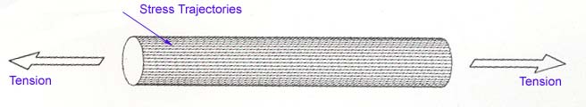 |
These lines are formally known as "stress trajectories" Picture concept adapted from "High Performance Hardware"; Forbes Aird |
||||||||||||||||||||||||||||||||||||||||||||||||||||||||||||||||||||||||||||||||||||||||||||||||||
Now here's the thing about stress trajectories - they have to flow, like water. They flow through and along a material. They cannot flow through space or air. That means, if a stress trajectory is happily flowing along and then suddenly meets space, for example if there is a sharp corner, a notch, or a hole in the part, it gets very unhappy. It cannot simply stop, or leap out into space - it has to bunch up with other stress trajectories to go around the interruption. This causes a concentration of stress. Picture it like water flowing along in a stream - if there is suddenly a rock in the middle of the stream, the water must bunch up and flow around it. In the stream, we would see this as turbulent water or eddies in the stream around the rock. In our steel part under load we cannot see the bunched up stress trajectories, but they are there, and we sure as heck need to account for them. |
|||||||||||||||||||||||||||||||||||||||||||||||||||||||||||||||||||||||||||||||||||||||||||||||||||
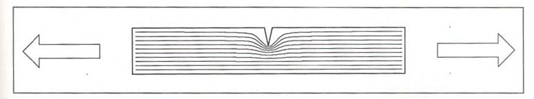 |
Stress Trajectories bunching up as they are forced to dodge around a notch, creating a stress concentration. Picture from "High Performance Hardware"; Forbes Aird |
||||||||||||||||||||||||||||||||||||||||||||||||||||||||||||||||||||||||||||||||||||||||||||||||||
| You see, the thing about stress bunching up, is that it is now concentrated - and that can and will cause failures. For example, imagine our plain steel shaft has a cross sectional area of 1 square inch. Suppose we placed a tensile force of 100 pounds on it. The uniform stress in the shaft would be 100 psi, with all the stress trajectories happily running along the length of the bar. Now suppose we cut a notch in the shaft, or reduced its diameter - suddenly some of the stress trajectories would have to bunch up to get around the interruption, causing a stress concentration. Mathematically we have suddenly reduced the cross sectional area in that spot to < 1 sq. in. so that the 100 lb force is divided by <1 sq. in. so that the stress, in pounds PER square inch, goes up. The severity of the stress concentration depends on how suddenly the area changes, and any change in shape or area that causes the stress trajectories to focus into a smaller area,(to bunch up), will produce a stress concentration - holes, notches, grooves, cracks, radius changes, are all guilty. These areas of stress concentration are known as "stress raisers". In our example, let's assume the ultimate tensile strength of the shaft was 150 psi. When we pull on the unmolested shaft with a force of 100 psi, the shaft is fine - it carries the load without problem. However, once we add a stress raiser, we can easily cause the stress to concentrate in that area to a level above the UTS of 150psi, causing the shaft to rupture at that point EVEN THOUGH WE ARE ONLY PULLING ON IT WITHH 100 PSI, LESS THAN THE UTS!! | |||||||||||||||||||||||||||||||||||||||||||||||||||||||||||||||||||||||||||||||||||||||||||||||||||
 |
Stress trajectories at varying degrees
of concentration, causing stress raisers Picture from "Engineer to Win" |
||||||||||||||||||||||||||||||||||||||||||||||||||||||||||||||||||||||||||||||||||||||||||||||||||
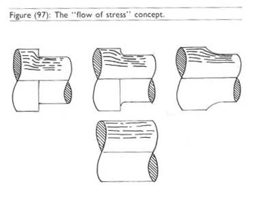
| Of course, not all stress raisers can be eliminated - we have to drill holes in things, things have to have corners and shape changes, and in the case of front axle shafts there need to be shaft diameter changes (section changes). The key is, to make changes in shape as gentle and smooth as possible. Any time there is a section change, no matter how small, there must be a fillet radius - and the radius must blend smoothly into both adjacent surfaces. There can be no exceptions if we expect the part to live.[2] | |||||||||||||||||||||||||||||||||||||||||||||||||||||||||||||||||||||||||||||||||||||||||||||||||||
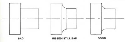 |
Picture illustrating the concept
of a fillet radius. Part on the right has it. Picture from "Engineer to Win" |
||||||||||||||||||||||||||||||||||||||||||||||||||||||||||||||||||||||||||||||||||||||||||||||||||
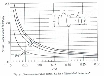 |
Graph illustrating the effect of proper fillet radii on stress concentration The fillet radius is labelled "r" in the shaft diagram. Note that as the radius of the fillet (r) gets larger r/d (horizontal axis) gets larger, and the stress concentration goes down. This effect is magnified the larger the section change. In other words the bigger the difference between the small part and the large part of the shaft, the more critical the fillet radius. Picture from Machinery's Handbook |
||||||||||||||||||||||||||||||||||||||||||||||||||||||||||||||||||||||||||||||||||||||||||||||||||
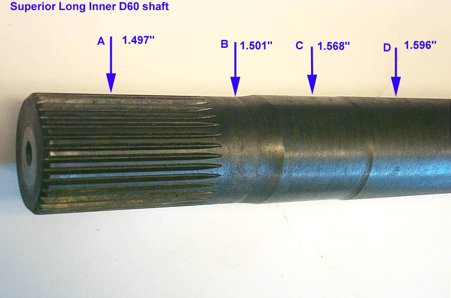
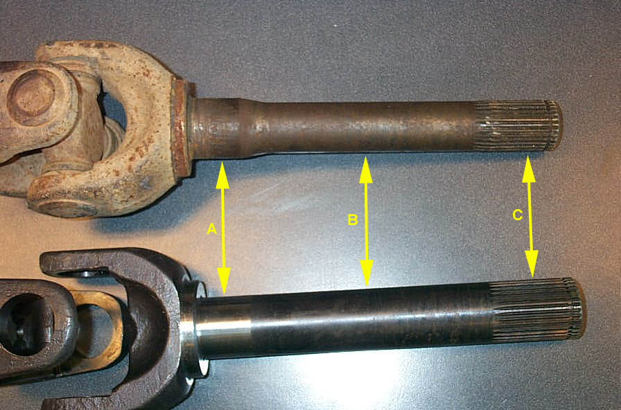
ProfileWhat do we mean by a shafts profile? As illustrated by the following 3 pics, when we speak of a shafts profile, we mean the various diameters along its length, (its section changes) from the splined end to the yoke. |
|||||||||||||||||||||||||||||||||||||||||||||||||||||||||||||||||||||||||||||||||||||||||||||||||||
|
Superior Alloy shaft - D60 long side inner. | ||||||||||||||||||||||||||||||||||||||||||||||||||||||||||||||||||||||||||||||||||||||||||||||||||
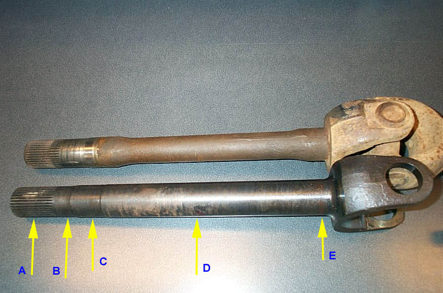 |
Spicer (top) and Superior Alloy D60 short side inner shafts. | ||||||||||||||||||||||||||||||||||||||||||||||||||||||||||||||||||||||||||||||||||||||||||||||||||
 |
Spicer (top) and Superior alloy D60 stub shafts. | ||||||||||||||||||||||||||||||||||||||||||||||||||||||||||||||||||||||||||||||||||||||||||||||||||
SummarySo to briefly recap:
What does all this have to do with the "ultimate" shaft? Well, ultimately, how "strong" a shaft is, how much abuse it can stand, how much load it can carry is very much affected by the shafts profile - specifically in the following areas:
Let's examine each in turn: The Spline Stress Raiser and Working DiameterEvery splined axle shaft has at least one huge stress raiser by virtue of it's design. The point at which the splines end is natural stress raiser. Why should this be so? Imagine a wheel wedged between 2 rocks, but the throttle pressed and torque applied to the axle shaft. The splined portion of the shaft, engaged in the carrier, is, in a manner, held fast. Because the wheel is held steady, the shaft will immediately twist. Because the force is input via the carrier, we can instinctively imagine how the stress would concentrate where the splines end. The concept would be similar to the following example: chuck a thin stick of wood vertically in your vice, sticking up a couple of feet. Apply a force to the top of it by pushing, and you already know where it will snap - right where the jaws of the vice clamp it. Same deal with the splines. Now, admittedly the torsional stress an axle shaft experiences is significantly more complicated (being a combination of tension, compression, and shear) than the simple tension or shear stress examples we have been using to illustrate concepts - however, we can still use these simple models to understand the concepts. Here's what Carroll Smith has to say, in his usually extremely blunt fashion, about splined shafts profile, particularly in the area of the end of the splines. |
|||||||||||||||||||||||||||||||||||||||||||||||||||||||||||||||||||||||||||||||||||||||||||||||||||
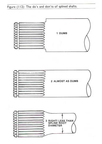 |
Splines MUST be placed on a diameter that is greater then the operating diameter of the part, or they must be eliminated from the design. Spline roots must never be allowed to blend into the operating diameter.[3] | ||||||||||||||||||||||||||||||||||||||||||||||||||||||||||||||||||||||||||||||||||||||||||||||||||
So, in order to deal with the spline stress raiser, the textbook way to build an axle shaft is to make the operating diameter of the shaft smaller than the diameter of the splines. This not only serves to reduce the stress raiser at the root of the splines, but, if we re-examine the equation for torsional deflection, we can easily see how this reduced diameter also allows the axle shaft to twist more. Recalling how energy is converted, this twisting allows the shaft to convert the energy (mainly into heat through internal friction) as opposed to just transferring it where it would break U-joints, ring and pinions, driveshafts, transmission outputs, etc. As we discussed under material - the key is then to build the shaft from a high enough quality material to be able to handle this twisting comfortably withing the elastic range. This "reduction of shaft diameter after the splines" is often commonly referred to (and often with a negative connotation) as "neckdown". This proper neckdown IS NOT to be confused with what the OEM's do (e.g. notorious D44 front axle neckdown). That OEM Spicer neckdown is done either as a manufacturing convenience (to facilitate quick, easy splining) or to introduce an intentional design weak point (so that if the ring and pinion fails/seizes in 4wd the shaft breaks and the wheels remain free and steerable as opposed to the front wheels locking up) - depending on who you ask. Note that there is a discrepancy between this neckdown rule, and making the diameter of the shaft as large as possible for maximum strength. Like all design - there is a trade off and a compromise must be reached. With this in mind, consider that when building a stock-replacement axle to fit into existing carriers, the manufacturer is limited to an existing, exact spline size - they can't make it larger or smaller - the splines have to fit the carrier. So, in order to obey the neckdown rule, they would have to make the shaft, in the case of a D60, smaller than 1.50". This may well cross the line of diminishing return. In other words, when the final engineering analysis is done, it may turn out that keeping the shaft operating diameter at 1.50" actually imparts greater overall load carrying capacity/strength to the shaft than would obeying the neckdown rule. Add in the strength of the materials, as well as the cost/complexity factor of manufacturing an axle with a neckdown and we begin to get a clearer picture. There are, in fact, no aftermarket companies that I'm aware of making replacement shafts for Dana axles with this particular profile feature, the proper neckdown - not even Superior. I asked around amongst all my contacts and tried to find out why - nobody's talking. I suspect that the added complexity and expense of this design, especially when balanced against the wide design margin afforded by the high quality materials (heat treated 4340) in use amongst the top companies, and the trad-off in strength vs shaft diameter, when coupled with an analysis of the shafts required duties (in a rock-crawler, as opposed to drag car etc.) that the decision is that it's just not worth it. I do know, however, that certain axles built by Sandy Cone and other suppliers to the big $$ trophy trucks have the textbook neckdown profile - it's just not common on front D60 4x4 shafts. The concept of equal torque.There is one more important aspect of axle shaft profile we should examine before moving on, and that is the concept of equal torque. Imagine climbing a steep, rocky climb. You need to get your foot into it, and as result you're hopping and skidding all over the place with the weight bouncing around and the tires alternately spinning and then suddenly grabbing traction. This is a nightmare for axle shaft survival - but a scenario we commonly encounter and expect our parts to survive! In this scenario, or any other high-load situation, the axle as an assembly has the greatest chance of survival if both shafts survive. For both shafts to survive - the best scenario is for them to share the abuse / stress; to participate equally in sharing the load. However, there's one big gotcha - almost always one shaft is dramatically shorter than the other. In my own GM Dana 60, the long side shaft is 35" long, or about 50% longer than the 18" short side shaft. The problem with this becomes evident when we recall once again our friend the angular deflection equation (math is soooo cool :-) alpha=[584(T)(l) ] / D^4 * G Where: alpha = the torsional deflection
in degrees (how much it twists) In my front axle in any given "all wheels driving" situation, for each shaft G and T are equal, or about equal, and l is quite different: meaning that if D is constant between the 2 shafts, the longer shaft will twist more than the short. This will normally allow the energy to be dissipated better in the longer, greater twisting shaft than in the short shaft - this explains why quite often we see more broken short side axles than long. The converse is also possible, depending on the nature of the loading on the axle (magnitude, axle material, etc), the long side axle may fail prematurely because it twists so much more than the short side. Either way this explains why some rigs perpetually break one side or the other. Regardless, the optimum situation is to have both shafts share the load and twist equally - thereby creating the most reliable and predictable assembly. This concept is the concept of equal torque. On last look at the equation, and we see that for either shaft of any given axle we can't change l or G, and we have no real way to predict or control T (except let up on the loud pedal - and what fun is that?) so the only way to achieve equal torque loading of the shafts is to alter D between the shafts. Note that D is raised to the fourth power so that small changes in shaft diameter have relatively large effects on how much the shaft will twist. A well made axle shaft will take this into account. Again, it will come as no surprise that Superior do, in a process they call their "exclusive (patent pending) Torque Equalizing Diameter Profile" OK, so if we understand material, heat treatment, neckdown, operating diameter, and torque equalization, it's time to consider the last factor in shaft design - splines. Axle Spline TechnologyThe actual splined section of an axle shaft has a dramatic effect on the overall strength of an axle shaft; from their size, shape and angle to how they were made and how well they fit in the carrier. |
|||||||||||||||||||||||||||||||||||||||||||||||||||||||||||||||||||||||||||||||||||||||||||||||||||
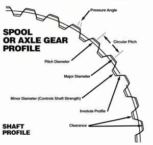 |
A splined shaft has a minor and major diameter and is further classified by the shape of the splines, the pressure angle, the number of teeth, and the diametrical pitch. | ||||||||||||||||||||||||||||||||||||||||||||||||||||||||||||||||||||||||||||||||||||||||||||||||||
Major and Minor Diameter.As illustrated in the diagram above, the major diameter is the diameter of the splined section of the shaft measured at the outside or tips of the teeth of the splines. The diameter of the shaft at the bottom of the grooves between the teeth is the minor diameter of the splines. Shape |
|||||||||||||||||||||||||||||||||||||||||||||||||||||||||||||||||||||||||||||||||||||||||||||||||||
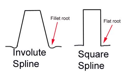 |
Splines are either "square" or "involute" in shape. Involute splines have teeth with a profile as shown in the above pic where the tip is narrower than the base. Involute splines have 3 distinct advantages over square cut:
|
||||||||||||||||||||||||||||||||||||||||||||||||||||||||||||||||||||||||||||||||||||||||||||||||||
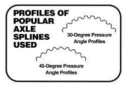
Square cut splines are quite old-fashioned and are rarely used anymore. However, I mention them because some aftermarket axle shaft shorten-and-respline outfits cut splines using equipment that is not able to reproduce the correct involute spline profile. This is a disaster because, even if you can get the square cut splined shaft to engage with the involute spline carrier, the contact points will be focused on a very concentrated area, causing enormous stress concentrations - and we know all about avoiding them, don't we!. The only way to produce the correct involute spline is to roll, hob, or cut them using a single point cutting process with a correctly shaped cutter. Axles that have been made or resplined using a flycutting procedure will NOT have proper involute splines. In addition to the shape of the tooth, splines also have either a fillet root or flat root. The root of the spline is the area where the tooth originates from the shaft. As you can imagine, the root would be an enormous concentration of shearing stress. Recall from our discussion on the flow of stress that a fillet radius will help relieve this concentration of stress, which must be balanced against the slightly smaller minor diameter that results. Most of our axles are fillet root. Pressure angleNot all involute splines are the same shape - there are variation in exact "tooth shape" possible. These differences in tooth shape are known as the pressure angle of the spline. The pressure angle is the basic included angle of the spline tooth (see diagram above). Common axle spline pressure angles are 30° (60° included angle) and 45° (90° included angle). 45° pressure angle splines offer a slight strength advantage because for a given major diameter spline the teeth of a 45° spline are shorter-allowing for a larger minor diameter size. Dana and some GM axles are 30°, Ford, Toyota, some GM, and most racing axles are 45°. Some Rockwell and older axles are 37.5° pressure angle. The most important thing is to ensure you MATCH the pressure angle of the shaft with the pressure angle of the carrier being used. It is no good at all to try and cram a 45° pressure angle aftermarket axle shaft into an OEM 30° pressure angle carrier - like forcing a square cut spline in an involute carrier, the stress would be focused on far too small an area creating uneven pressure points and unacceptable stress raisers begging for failure. |
|||||||||||||||||||||||||||||||||||||||||||||||||||||||||||||||||||||||||||||||||||||||||||||||||||
 |
|||||||||||||||||||||||||||||||||||||||||||||||||||||||||||||||||||||||||||||||||||||||||||||||||||
Diametrical PitchDiametrical pitch of splined shaft is a specification that relates the number of splines to the size of the shaft. This spec is what allows us to refer to an axle as just "35 spline" and be able to compare it to a "30 spline" axle without having to also list the minor and major diameters of the shafts. For example, almost anyone would instinctively tell you that a 35 spline shaft was stronger than a 30 spline shaft. But what if the 35 spline shaft had a minor diameter of 1 inch and the 30 spline shaft had a minor diameter of 2 inches? I can tell you without doing the engineering math that the 30 spline 2' shaft would be stronger. To avoid this confusion, and indeed to insure that the number of splines and the size of the shaft are standardized so that the teeth are evenly spaced and parts can be made to fit together, we have the concept of diametrical pitch. We are familiar with the fact that there are a limited, set number of standard threads-per-inch available that match certain bolt sizes (e.g. a 3/8" bolt has either 16 (coarse) or 24 (fine) threads per inch) so that we may have a reasonable chance of finding nuts and bolts that fit together - can you imagine if the number of different threads per inch for any size bolt were unlimited?!! In the same way, splined shafts must have a limited number of possible diameter and # of teeth combinations. Instead of threads-per-inch, diametrical pitch is used. The pitch diameter of a splined shaft is is the mid-point between the major and minor diameters. The diametrical pitch is the number of teeth per inch of pitch diameter, similar to the number of threads per inch specified for bolt threads. Because the splines are all the same size and shape, the distance between the centreline of adjacent splines (the circular pitch) remains constant. Therefore as the pitch diameter of the shaft increases, more teeth can "fit around" the pitch diameter, and therefore the larger the shaft diameter the larger the number of splines for any given diametrical pitch. An actual diametrical pitch specification will be a number specifying the number of teeth per inch of pitch diameter. Industry standards state that most modern automotive axle shafts (All of the 28, 30, 31, 35, 40 spline axles that interest us) are 24-pitch. Therefore, if the shaft had a 1-inch circular pitch diameter it would have exactly 24 splines (or teeth). Using this standard diametrical pitch of 24-pitch a 35-spline axle has a major diameter of 1,500 inches; a 40-spline 1.708 inches. Note that if you know the diametrical pitch of a splined shaft you can calculate its major diameter. This may be counter-intuitive, as it may seem as if one would decide to use a 1.5" diameter shaft, and then decide to cut splines into and settle on 35 splines. This is not how it actually works, In reality, the pitch controls the major diameter, as the following equation demonstrates. Using the equation you can calculate the number of splines on any size shaft or conversely the size of any shaft given the pitch and number of splines. Major Diameter Do=(N+1)/P Where: Do = major diameter of splined shaft If you know any 2 of the 3 variables you can simply rearrange the equation algebraically and compute the third/ For example: Q: What is the major diameter of a 35 spline shaft? A: N=35, assume P=24, Do=(N+1)/p = (35+1)/24 = 36/34 = 1.50" Yipeeee! Fun with math again! Q: - What is the major diameter of a 30 spline Dana axle? Bonus question - what is the diametrical pitch of the fabled full-float GM 14 bolt axle shaft (and why the heck did they decide to be different from the rest of the planet?)
Methods of FormingWe have come to the final factor to consider in axle spline technology and indeed in the whole process of deciding which axle shaft is the best - and that is the topic of how the splines are formed in the shaft. There are basically 4 ways to spline an axle shaft: 1. Rolling the spline: This is a cold-working process. It is done by a huge and powerful hydraulic powered machine that presses the splines into the shaft with anything from 2,500 psi - 7,000 psi, depending on the shaft. Recall from part 1 of the article that this cold-working process produces a refined and more consistent grain structure, resulting in a stronger part. The rolling machine has 2 plates that are extremely hard dies with the appropriate spline shape to them. The axle is rolled between these plates, one top and one bottom, and the splines are thus cold formed into the shaft. This is the very best way possible to form a spline as it is a cold working process, it removes no material from the shaft, and finally because it is done prior to the axle shaft being heat treated (hardened). Compared to a spline cut after hardening, a properly rolled spline will be up to 30 or 35% stronger. There are VERY few companies capable of rolling splines. The only two I know of are Dana/Spicer and Superior Axle and Gear. The drawback (for a manufacturer) to rolling splines is that not only is the equipment very expensive, but it is also time-consuming to set up, so that it is only feasible to roll splines in axles in large batches. This explains why so few aftermarket axles have rolled splines, and why virtually no custom shafts will have rolled splines. 2. Hobbing: Hobbing splines is the second-best way to from a splined shaft. Many very specialized, highly custom race and drag axles have their splines hobbed. The spline hobber is a machine that cuts all the splines at the same time. Hobbing produces a true involute spline shape, and if done before the shaft is hardened, some would argue there is very little strength difference between hobbed and rolled splines. Practically speaking this is probably quite true, but rolling is still the very best method. You can tell a rolled spline from a hobbed or cut spline quite easily by looking at how the root of the splines terminates. |
|||||||||||||||||||||||||||||||||||||||||||||||||||||||||||||||||||||||||||||||||||||||||||||||||||
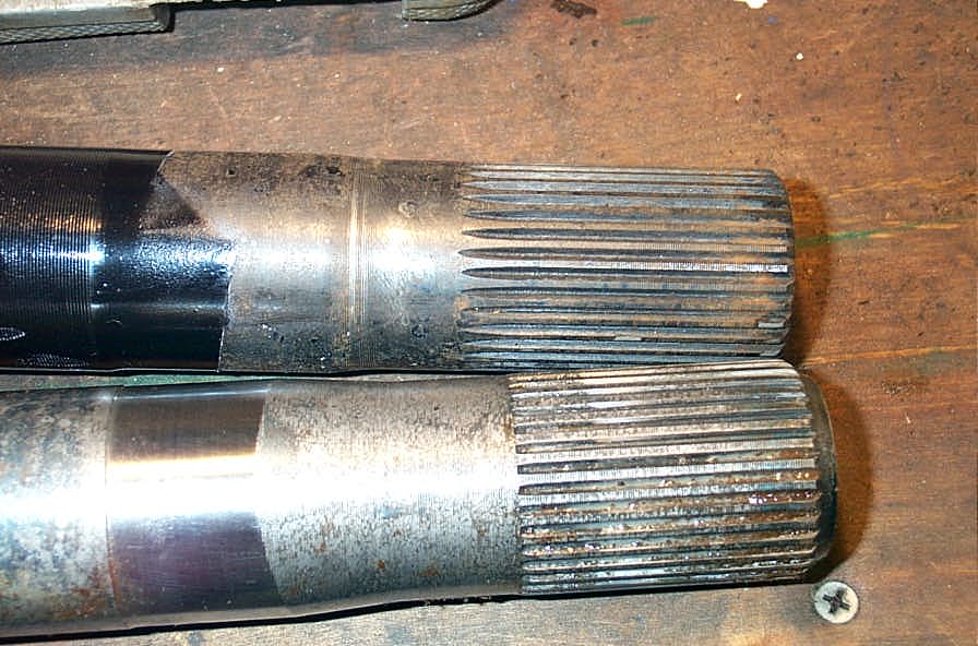 |
In this pic of D60 inner shafts, the top shaft is a pre-production Superior D60 shaft with hobbed splines, the lower is a Spicer inner shaft with rolled splines. Note the very square ends of the splines in the shaft with rolled splines, compared to the pointy ends of the hobbed splines. |
||||||||||||||||||||||||||||||||||||||||||||||||||||||||||||||||||||||||||||||||||||||||||||||||||
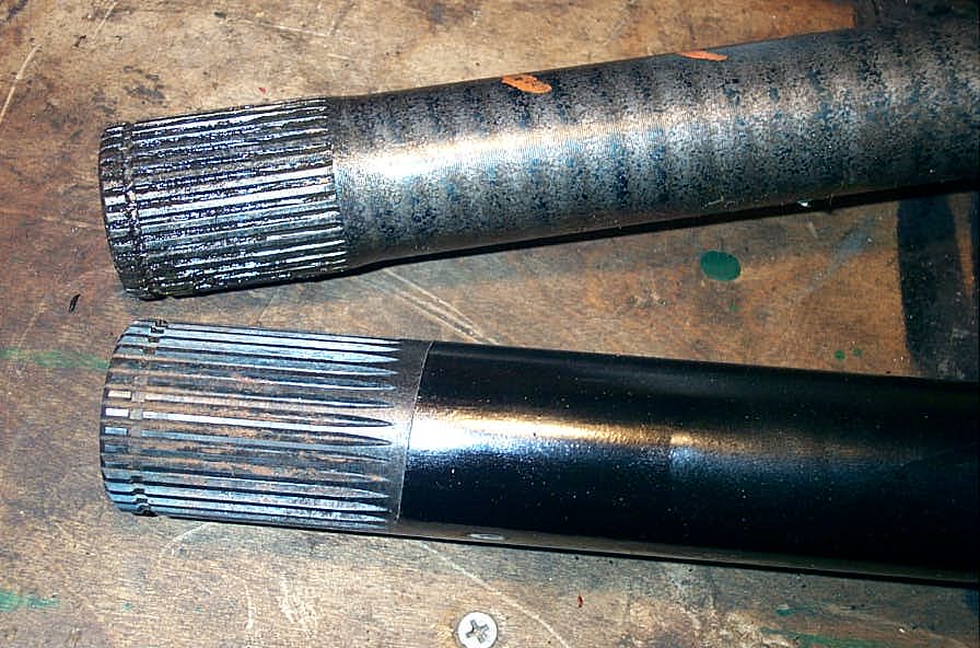 |
In this pic the top shaft is a Spicer stock D60 stub shaft with rolled splines, the lower is a Superior D60 shaft with hobbed splines. Again, note the different appearance. | ||||||||||||||||||||||||||||||||||||||||||||||||||||||||||||||||||||||||||||||||||||||||||||||||||
3. Spline shaping or cutting. There are many variations and different pieces of equipment that can and are used for cutting the splines. Using this method, the splines are cut one at a time. In many cases (e.g. flycutting splines) the cutting process does not produce a proper involute spline profile. Another problem with cutting splines, particularly in re-splining operations, is that it is done AFTER the shaft is hardened, and most often induction hardened too. However, acceptable results can be obtained if the cutting is a) done on a through hardened shaft
or; with an induction hardened shaft done either before hardening or only to
a depth that doesn't approach the hardened depth (this will depend on spline
size/pitch and case depth); and 4. Spline grinding: splines are ground into the shaft with a diamond or carbide tip grinding wheel. this is another process where splines are formed one at a time. I know very little else about this method and I don;t know if or who any 4x4 axle shaft manufacturers use spline grinding. Summary. Rolled splines are best but rare, hobbed splines (done before hardening) are almost as good, and cut splines have a number of issues and don't really qualify an axle shaft for "ultimate" status. Axle Failure AnalysisThis is a huge and very complicated topic in itself, and will be added at a later date. Failure analysis is complicated at best, and when one considers the effect of fatigue life, extremely difficult. For example, consider the calculation of the polar moment of inertia: The polar moment of inertia ,
J, of a cross-section with respect to a polar axis, that is, an axis at right
angles to the plane of the cross-section, is defined as the moment of inertia
of the cross-section with respect to the point of intersection of the axis and
the plane. The polar moment of inertia may be found by taking the sum
of the moments of inertia about two perpendicular axes lying in the plane of
the cross-section and passing through this point. Thus, for example, the
polar moment of inertia of a circular or a square area with respect to a polar
axis through the center of gravity is equal to two times the moment of inertia
with respect to an axis lying in the plane of the cross-section and passing
through the center of gravity. So there! Formulae and CalculationsFor the mathematically inclined and those that like to calculate stuff, here are some interesting formulae: Roy McBride and Dave Towers of Heriot Watt University excellent tutorial on Torsion of shafts with circular symmetry an MS Word .doc file. Also available in .pdf format ConclusionHopefully this brief look at the tech behind axle shafts has been informative and has shown that there's a lot more to the topic than might first appear. It should also greatly assist in discussions or debates about who or what is best . I certainly hope that it illustrates that in choosing shafts for the BV-60 I didn't just pull any manufacturer out of my hat. For an axle shaft to be considered the "ultimate" we must consider:
Notes: [1] "Machinery's Handbook" 24th Edition. Erik Oberg, Franklin D. Jones, Holbrook L. Horton, Henry H. Ryffel, Robert E. Green; Industrial Press Inc., 1992 p.475 [2] "Engineer to Win". Carroll Smith; Motorbooks International, 1985 p.115 [3] "Engineer to Win". Carroll Smith; Motorbooks International, 1985 p.119 [4] "Machinery's Handbook" 24th Edition. Erik Oberg, Franklin D. Jones, Holbrook L. Horton, Henry H. Ryffel, Robert E. Green; Industrial Press Inc., 1992 p.2034 [5] "Machinery's Handbook" 24th Edition. Erik Oberg, Franklin D. Jones, Holbrook L. Horton, Henry H. Ryffel, Robert E. Green; Industrial Press Inc., 1992 p.265 |
|||||||||||||||||||||||||||||||||||||||||||||||||||||||||||||||||||||||||||||||||||||||||||||||||||
|