 |
Ballistic Fabrication By Bill "BillaVista" Ansell |
IntroductionI love what the internet and on-line shopping has done for the availability of parts for our still relatively obscure (but growing!) industry. Now, anyone in the world has access to a huge array of parts that they simply didn't a few years ago. That said - if I'm making a substantial investment I really like to be able to physically handle the parts in question. I find that this is a great way to get a true feeling for the fit, finish, and quality of part - which years of experience has taught me is very often a great predictor of the overall quality, function, and reliability of a part. |
 |
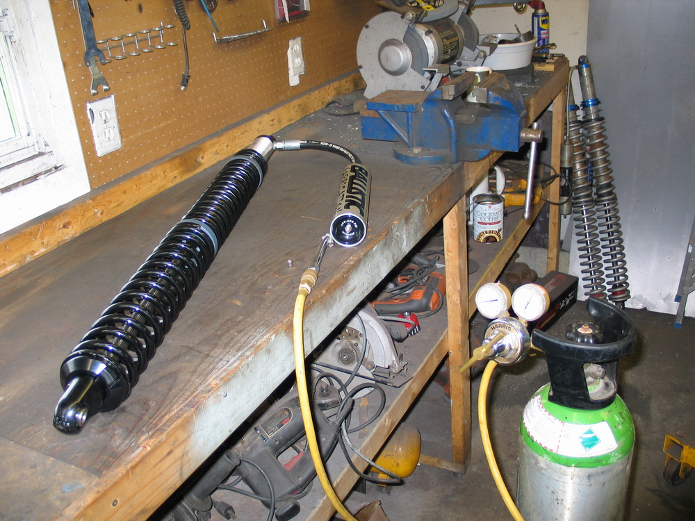
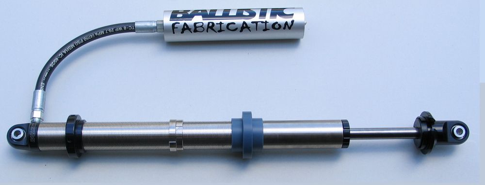
The problem is - there are some great parts available for your rig, and mine, that you simply can't go down to the corner store and check out. That's why, in my feature product reviews, I bring you so many high-quality digital images of the products I review - often from multiple angles. The goal is to produce an article that will be the next best thing to actually being able to handle the part yourself before making a purchasing decision. Such is certainly the case with this instalment - a full review of the recently released 16" Ballistic Coilover Racing Shocks. Ballistic Shocks are built in Tucson, AZ, USA in a partnership between Ballistic Fabrication - one of the fastest-growing offroad fabrication shops in the business; and ADS machine - a local Tucson machine shop with years of experience and a loyal following in the southwest racing and sand-car scenes. The shocks are built solely for Ballistic Fabrication using Ballistic's exclusive specifications. Designed for extreme use in race and recreational settings, Ballistic Shocks are manufactured on state of the art machining centres from high quality materials and are re-valvable, fully rebuildable and highly adjustable. A Detailed Look at the Ballistic Shocks |
|
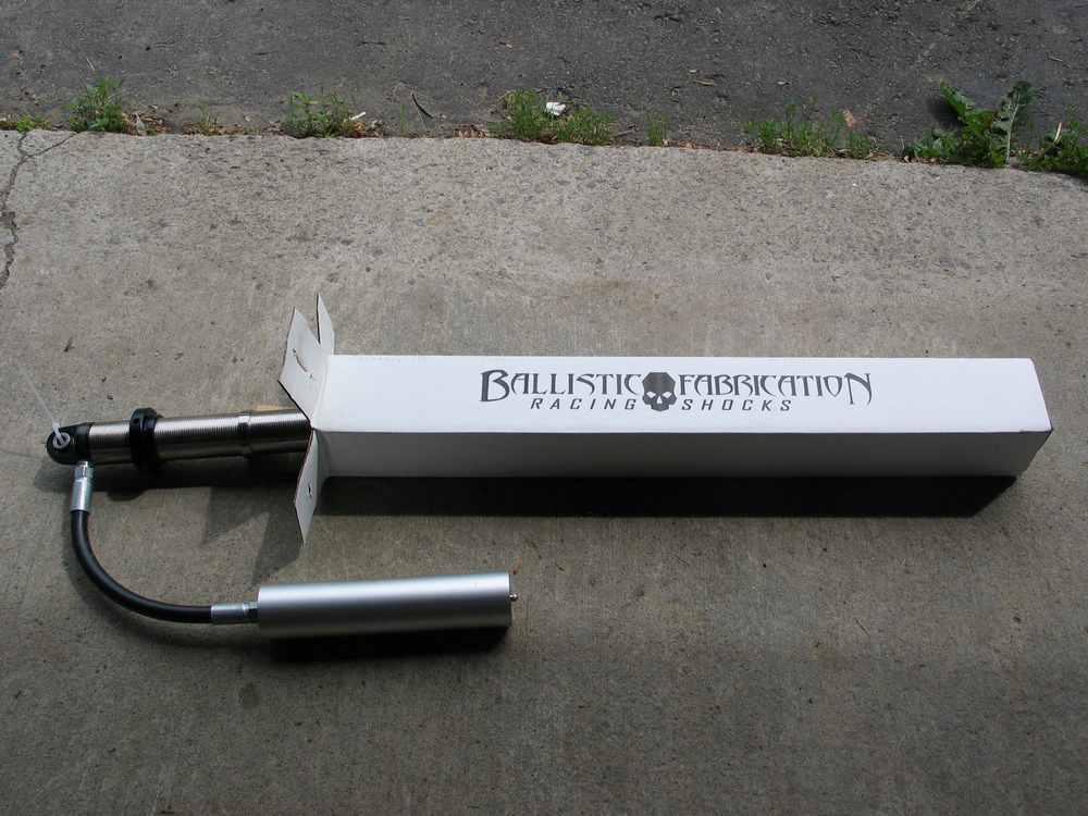 |
The shocks come packaged in their own snazzy boxes. | ||||||||||||||||||||||||||||||||||||||||||||
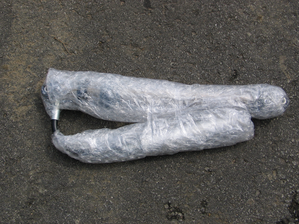 |
They are extremely well packaged in protective bubble wrap. | ||||||||||||||||||||||||||||||||||||||||||||
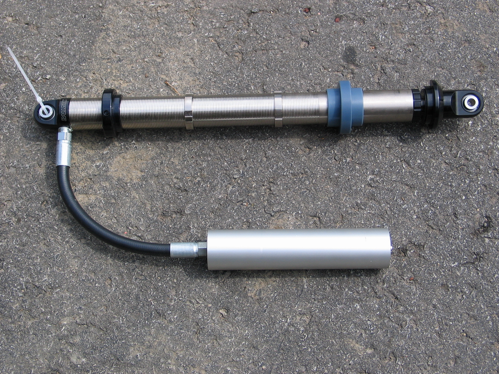 |
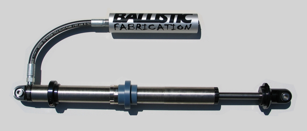
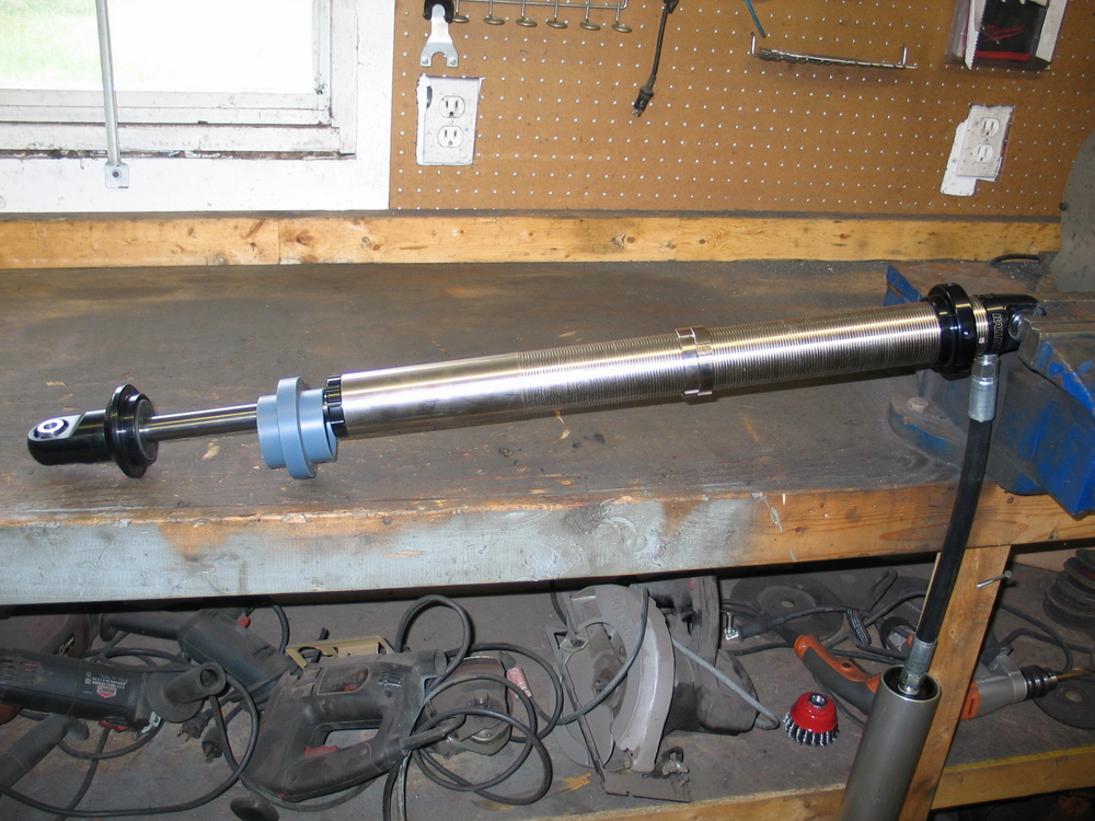
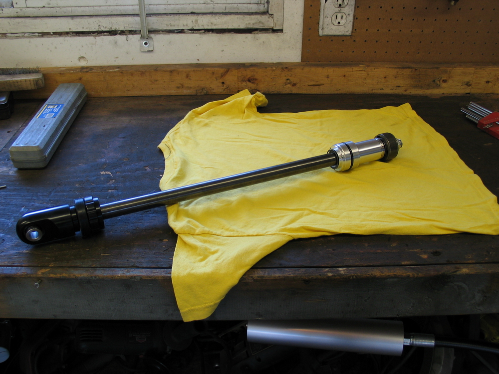
The minute I got them out of the box and unwrapped, the sheer beef and extremely high quality of the shocks was apparent. | ||||||||||||||||||||||||||||||||||||||||||||
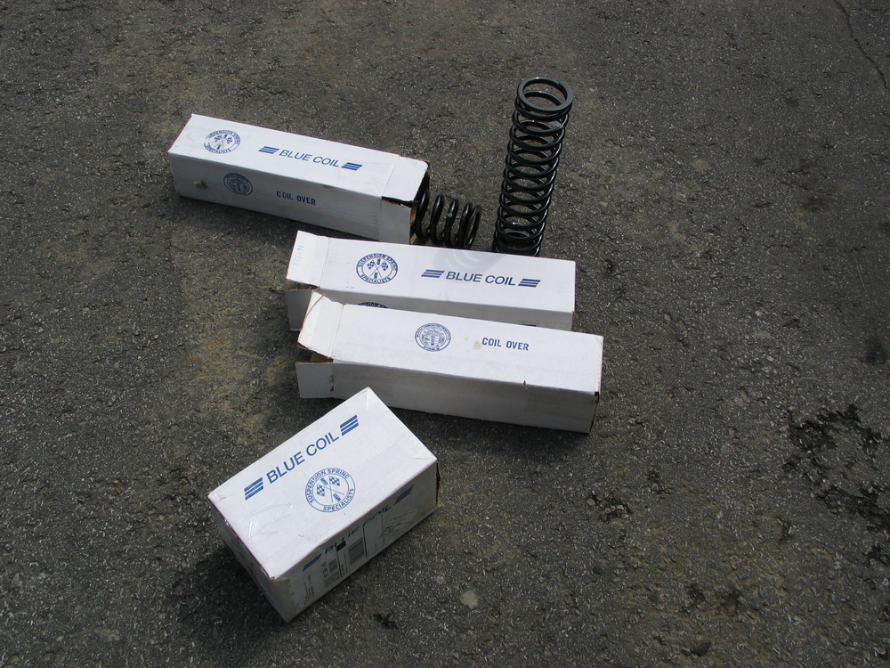 |
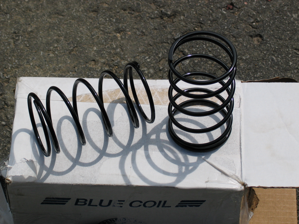
Ballistic shipped my shocks with Blue Coil coil springs in the lengths and rates that I had specified. Unique amongst current coilover shocks, the Ballistic Shocks are constructed with a shock body having a 2.125" outside diameter. However, they still use the common 2.5" ID springs. |
||||||||||||||||||||||||||||||||||||||||||||
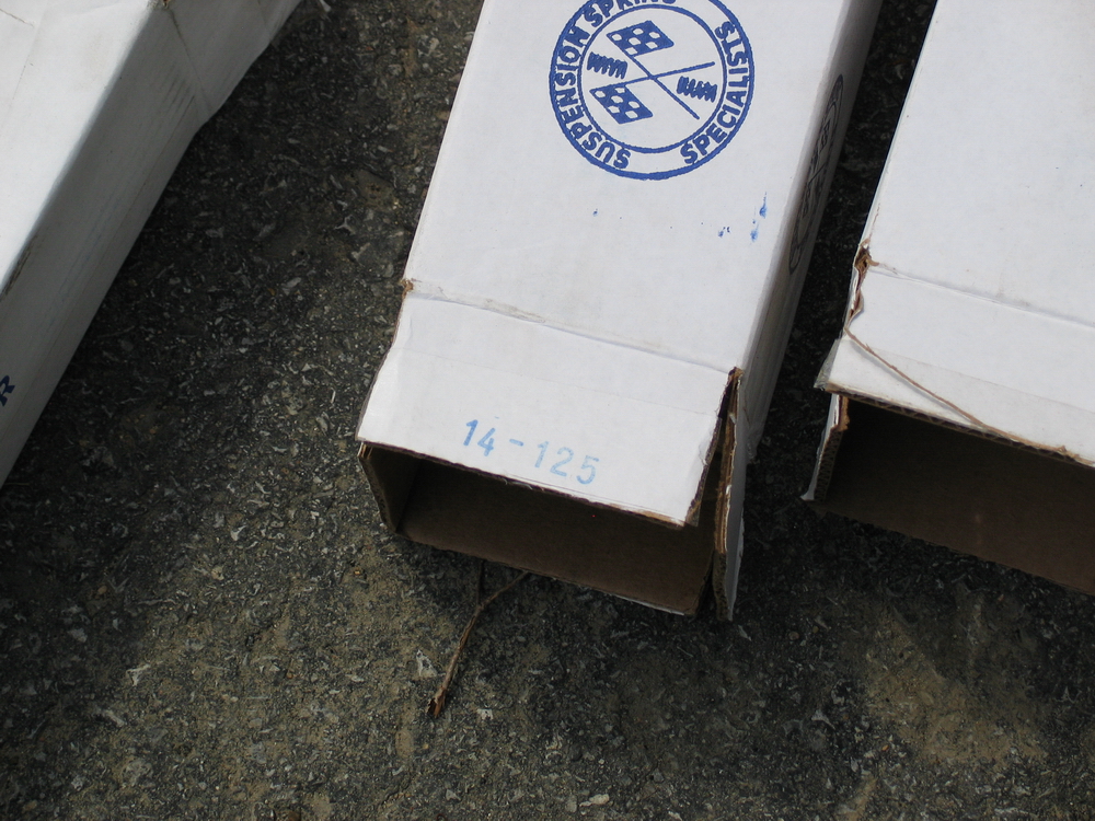 |
The Blue Coil springs have their length and spring rate indicated on the box... | ||||||||||||||||||||||||||||||||||||||||||||
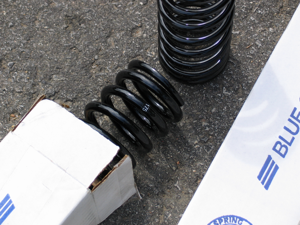 |
... and on the spring itself with a small tag. My springs were powdercoated in gloss black. |
||||||||||||||||||||||||||||||||||||||||||||
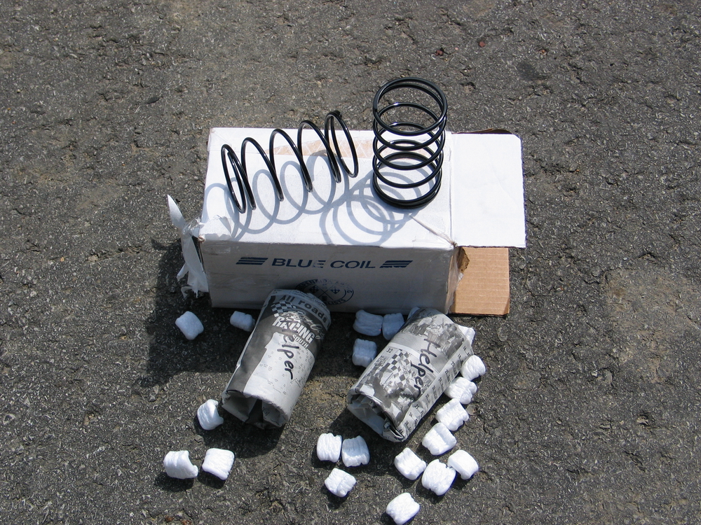 |
The Blue Coil helper springs (for triple-rate setup) are helical wound of circular-cross-section spring wire. | ||||||||||||||||||||||||||||||||||||||||||||
 |
They have a free length of 5 " and rate of about 20 lbs/in. | ||||||||||||||||||||||||||||||||||||||||||||
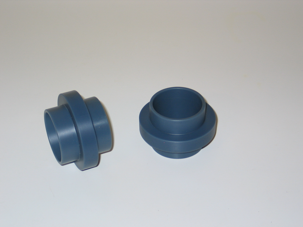 |
The double- and triple-rate sliders of the Ballistic Shocks are big and beefy. The sliders are machined from solid Nylatron ($$$), a bearing-grade graphite impregnated nylon that does not squeak like other sliders can. |
||||||||||||||||||||||||||||||||||||||||||||
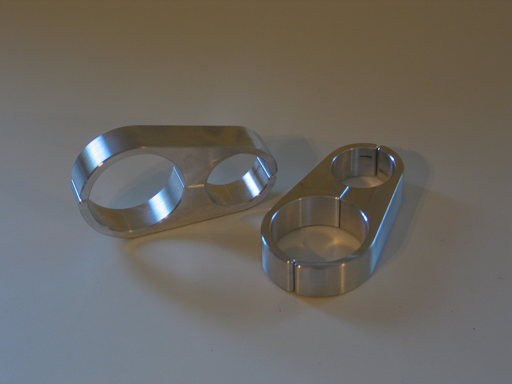 |
The shocks come with these bling aluminum remote-reservoir clamps that have a 2.5" ID section for the reservoirs and are available in 1.5" or 1.75" ID to match the tubing of your chassis. | ||||||||||||||||||||||||||||||||||||||||||||
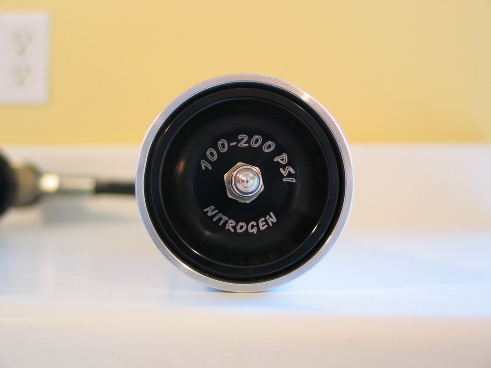 |
Schrader valve end of the remote reservoir. | ||||||||||||||||||||||||||||||||||||||||||||
 |
The reservoir's are 11" long and 2.5" in diameter. | ||||||||||||||||||||||||||||||||||||||||||||
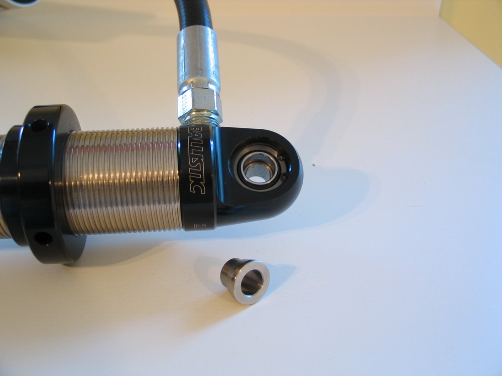 |
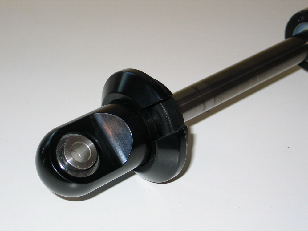
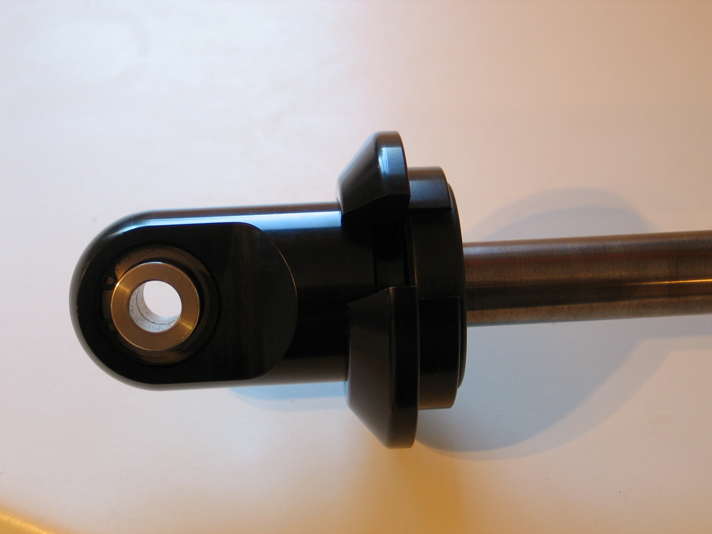
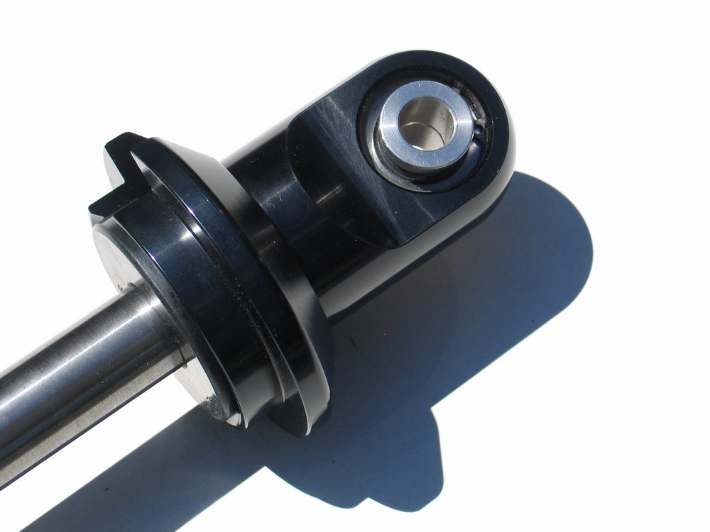
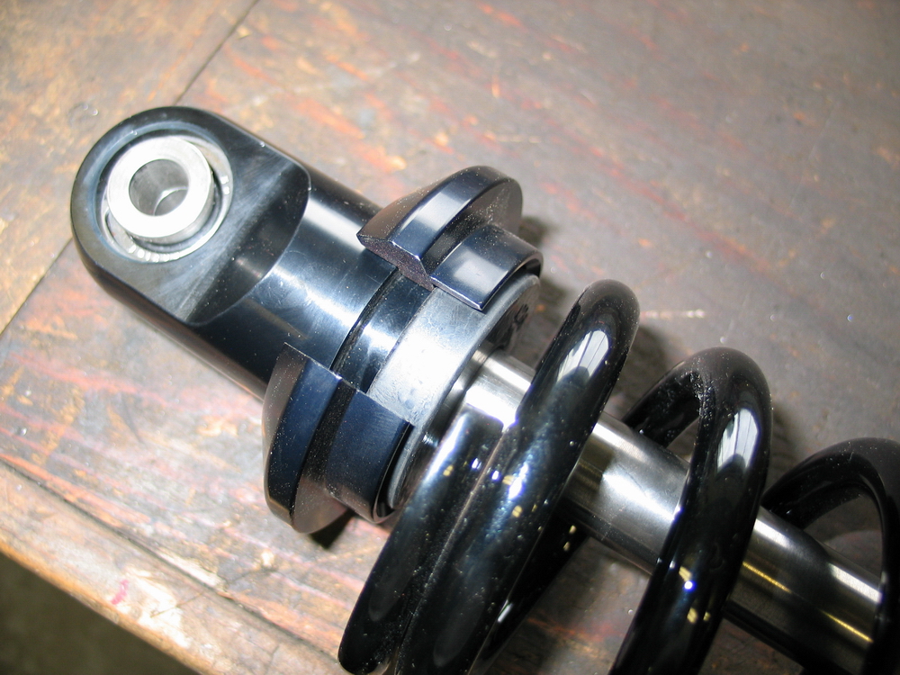
Here's a look at one of the features I love the most on the Ballistic Shocks - a feature I so appreciate that I literally yelled "hallelujah" when I saw it. The spherical bearings in the shocks have an oversize ID so that the custom misalignment spacers fit snugly into the bearing and are thus retained without falling out. Here one side is removed from the bearing. |
||||||||||||||||||||||||||||||||||||||||||||
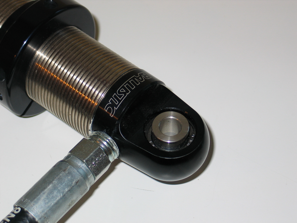 |
Here's a shot of the misalignment spacer installed in the bearing. The bearings themselves are high quality FK brand, made in the U.S.A. |
||||||||||||||||||||||||||||||||||||||||||||
 |
This may not seem like a huge deal - unless you've ever actually had to install a coilover with the little spacers that you have to hold in place either side of the bearing while trying to hold the shock in place and install the bolt all at the same time. Given that you have to do this every time you change springs (which you end up doing a lot during test and evaluation in pursuit of the perfect setup) the Ballistic bearing-and-spacer design is a godsend. |
||||||||||||||||||||||||||||||||||||||||||||
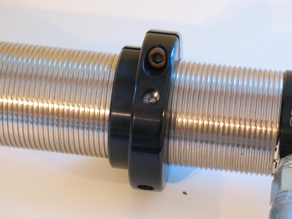 |
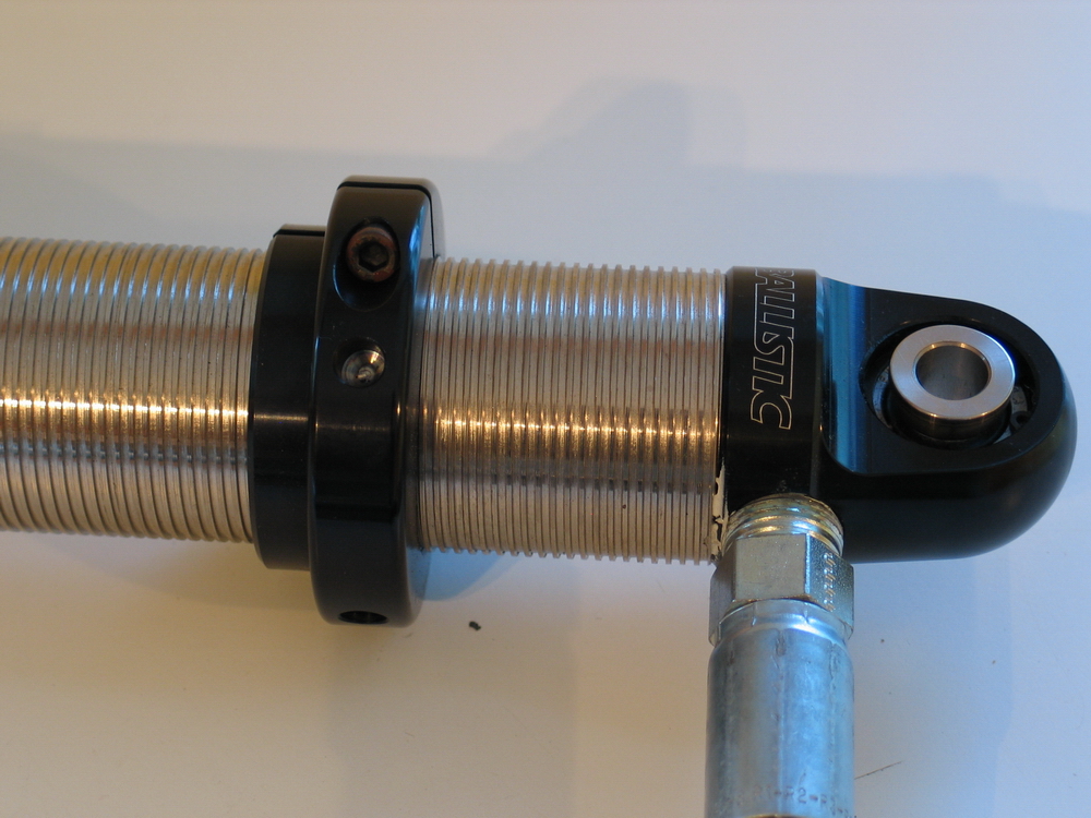
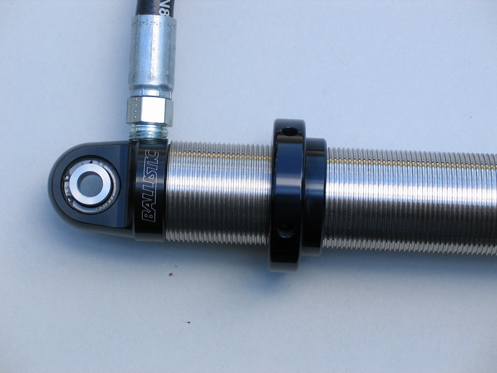
The upper spring seat (aka the "adjuster") is a single piece using a split-ring design that utilizes an Allen-head pinch-bolt to secure it in place. | ||||||||||||||||||||||||||||||||||||||||||||
 |
The stop-ring, used to set the transition from initial to final spring rate in a dual-rate setup, uses a double locking nut design. With this design, the lower ring is set to the desired height, and the top ring tightened down against it to secure both in place. It's a little tricky to do once the coils are installed on the shock (it helps to jack up the corner and allow the springs to droop free, giving more space between the coils, during on-vehicle adjustment) but this approach doesn't suffer when the coils rub (as they always will) like some other designs that use grub screws to secure the stop-ring. |
||||||||||||||||||||||||||||||||||||||||||||
 |
The Ballistic-specific sliders are big, beefy pieces that fit very nicely on the shock. Of course with the shocks having a unique 2.125" diameter body, they can't be interchanged with any other brands or designs. |
||||||||||||||||||||||||||||||||||||||||||||
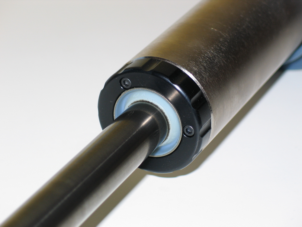 |
The bearing cap uses a high-quality seal and is retained with three Allen-head screws. | ||||||||||||||||||||||||||||||||||||||||||||
 |
Along with the bearing-and-spacer design, the Ballistic approach to the lower shock mount also helps make for quick and easy spring changes. There are no snap-rings involved, nor any tools required. |
||||||||||||||||||||||||||||||||||||||||||||
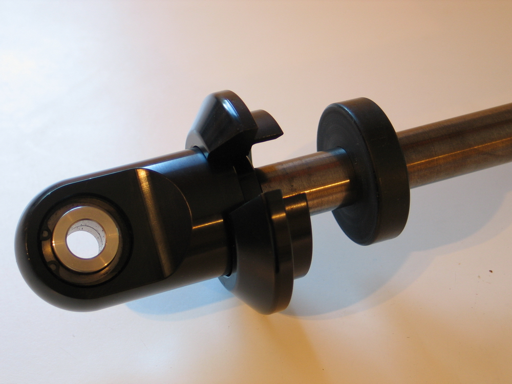 |
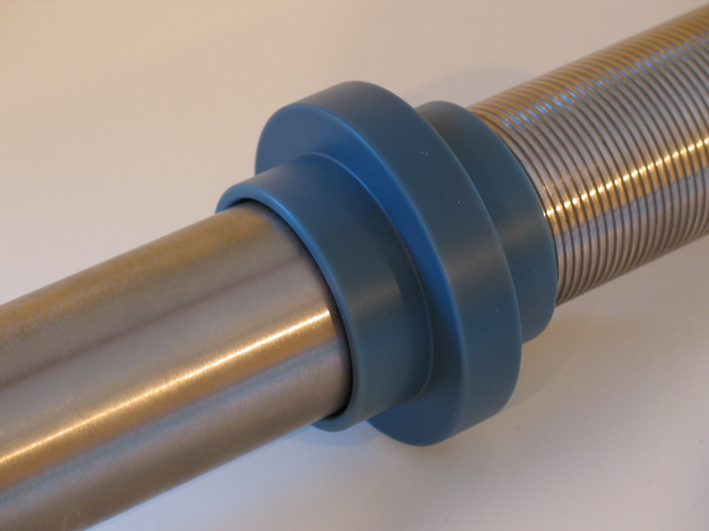
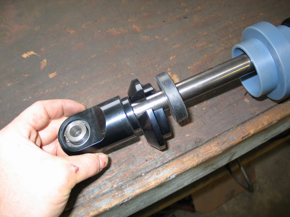
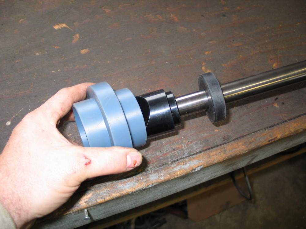
To remove the lower spring seat, you simply slide the rubber bumper up the shaft... | ||||||||||||||||||||||||||||||||||||||||||||
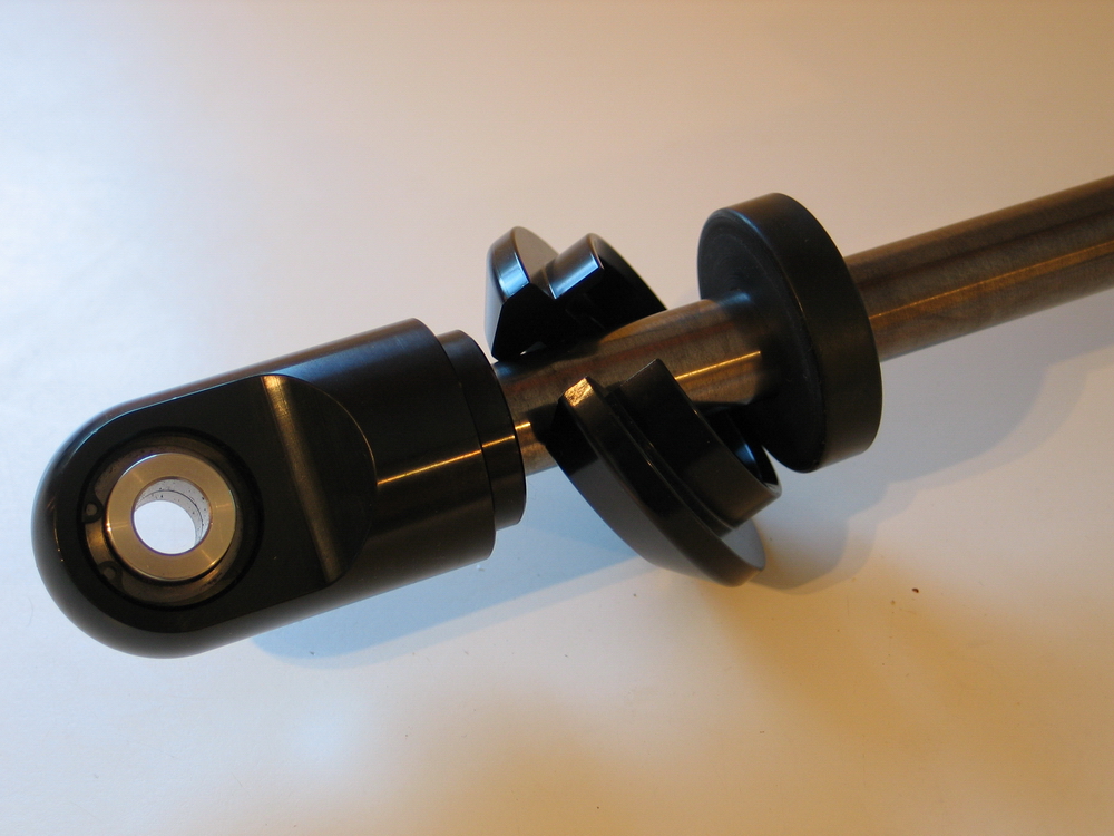 |
...slide the lower spring seat off the rod end... | ||||||||||||||||||||||||||||||||||||||||||||
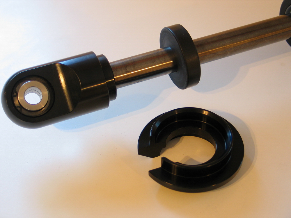 |
... and slip the gap in the seat over the shock shaft. It's that quick and easy. |
||||||||||||||||||||||||||||||||||||||||||||
 |
You simply reverse the steps to put the spring seat back in place. One of the great advantages to coilover suspensions is their high degree of flexibility and tuneability. In order to make the most of these abilities, however, a great deal of testing and trial and error are required. The combination of the integrated misalignment spacers and the quick-release lower spring seat used in the Ballistic shock design remove a lot of the heartache from such repetitive testing and trialing. |
||||||||||||||||||||||||||||||||||||||||||||
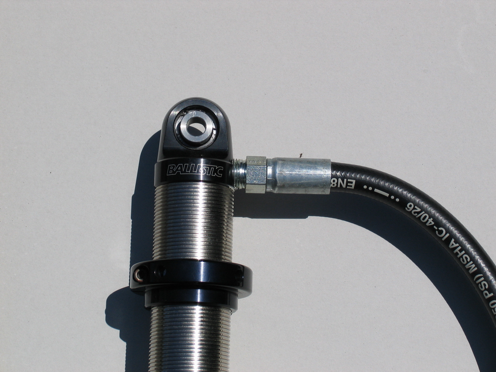 |
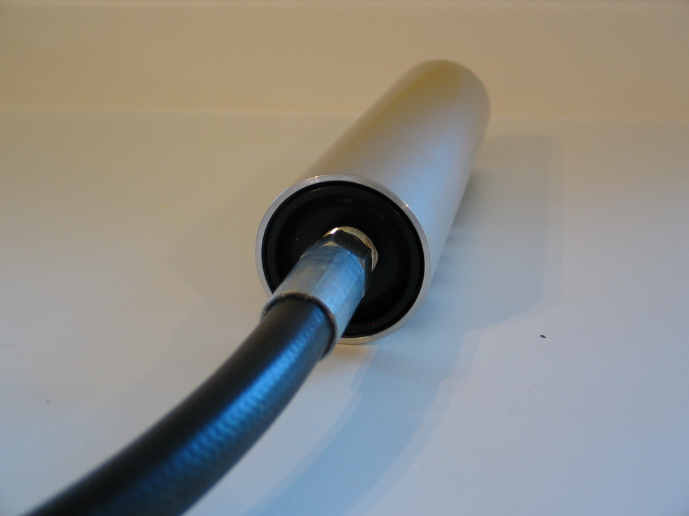
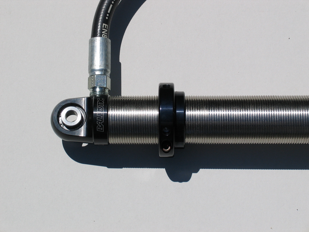
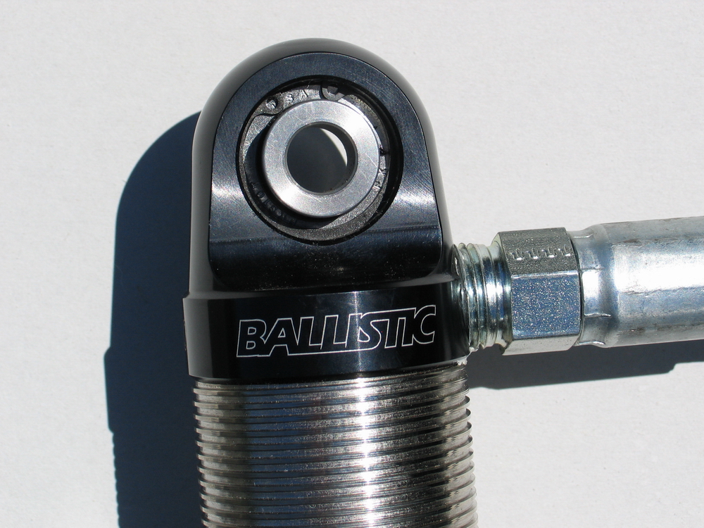
The Ballistic shock use a high-pressure Parker Hydraulics hose with straight NPT fittings to connect the shock to the remote reservoir. | ||||||||||||||||||||||||||||||||||||||||||||
 |
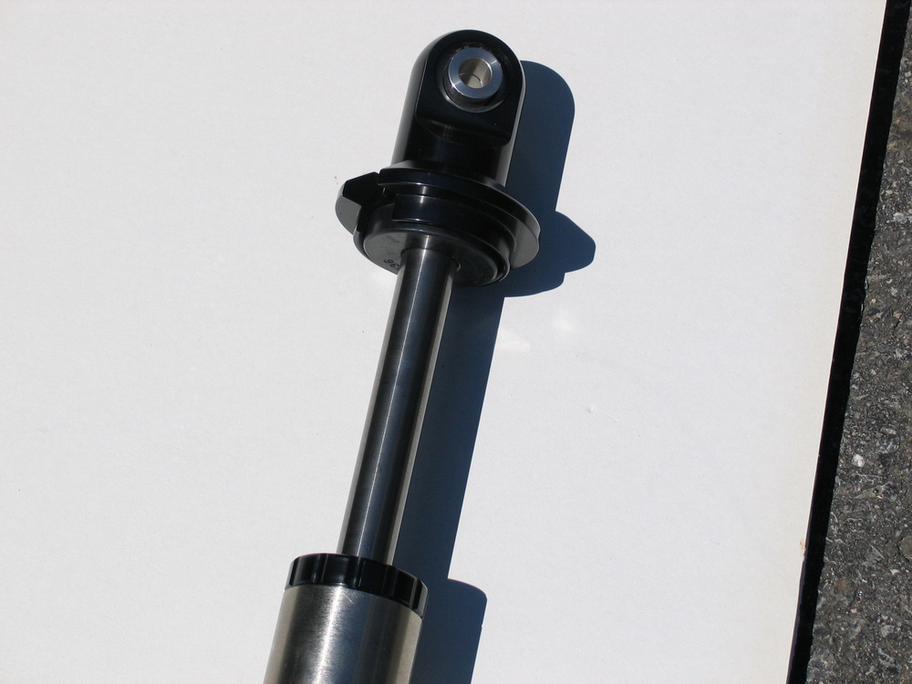
Shock, fully extended. | ||||||||||||||||||||||||||||||||||||||||||||
|
Shock, partially compressed. Another impressive feature of the Ballistic shocks, which can be clearly seen by expanding the picture to the left, is the fact that they have a far greater percentage of their body threaded than most any other shock. This translates into greater flexibility and adjustability with respect to spring length and ride height than otherwise possible. |
||||||||||||||||||||||||||||||||||||||||||||
 |
Reservoir with decal applied. | ||||||||||||||||||||||||||||||||||||||||||||
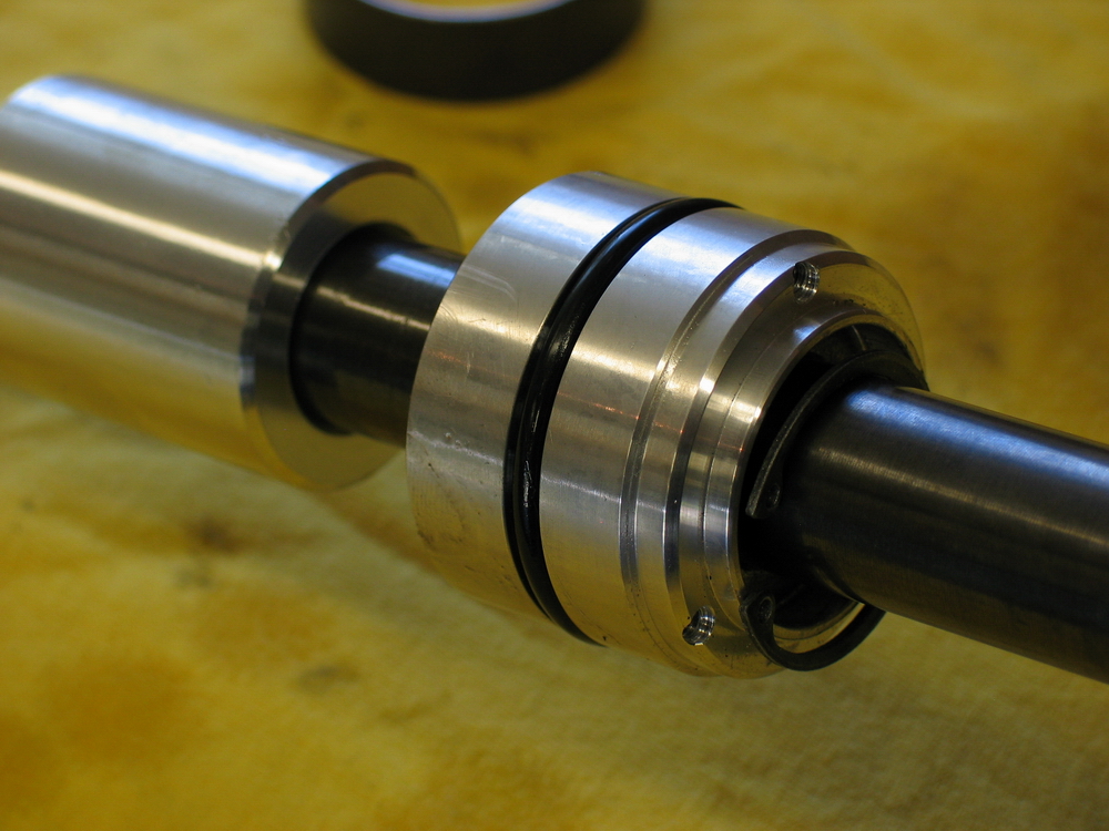
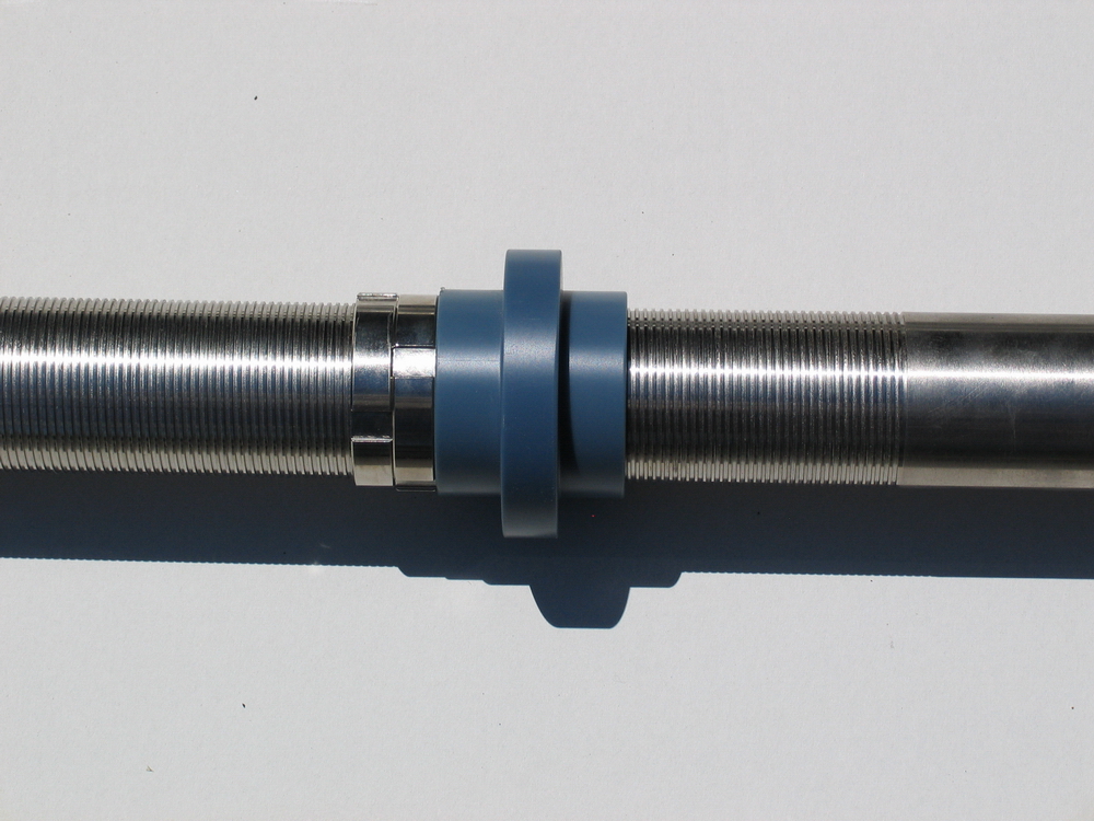 |
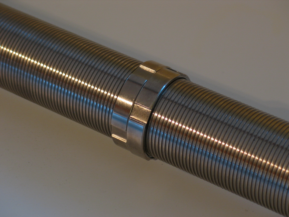
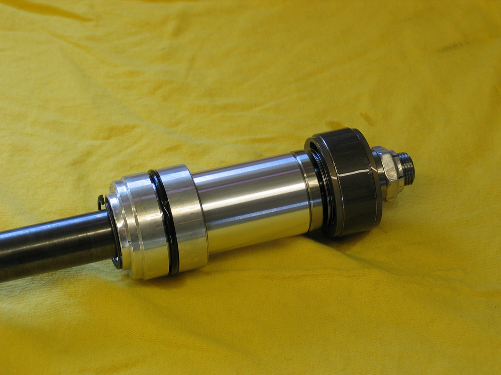
Dual-rate slider up against stop rings. The Ballistic shock bodies are electro-nickel plated for corrosion resistance. |
||||||||||||||||||||||||||||||||||||||||||||
 |
Upper end of shock, showing integrated misalignment spacers, remote reservoir hose, and upper spring seat. | ||||||||||||||||||||||||||||||||||||||||||||
 |
Lower or "rod end" end of shock, showing lower spring seat held in place by tight-fitting rubber bumper. | ||||||||||||||||||||||||||||||||||||||||||||
 |
Close-up of lower or "rod end" end of shock, | ||||||||||||||||||||||||||||||||||||||||||||
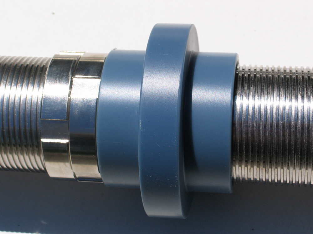 |
Close-up of dual-rate slider against stop rings. | ||||||||||||||||||||||||||||||||||||||||||||
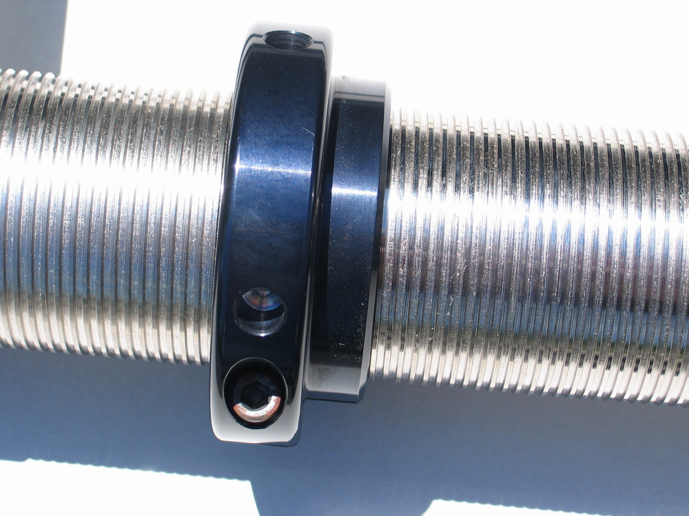 |
Close-up of upper spring seat. | ||||||||||||||||||||||||||||||||||||||||||||
 |
Close-up of top cap. | ||||||||||||||||||||||||||||||||||||||||||||
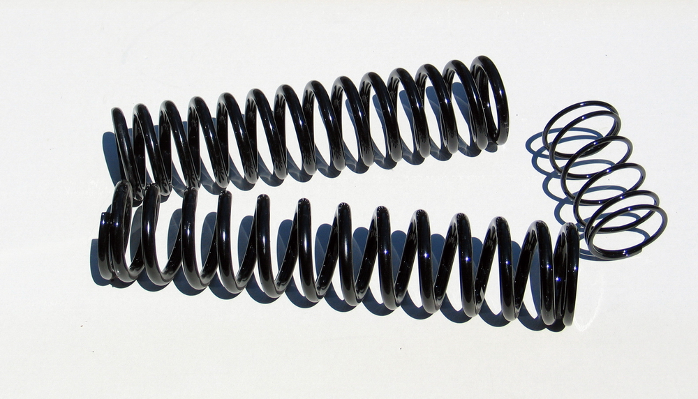 |
16" main spring, 14" tender spring, and 5" helper spring. | ||||||||||||||||||||||||||||||||||||||||||||
Ballistic Fabrication 16" 2.125" Series Remote Reservoir Coilover Shock Dimensions
Installation |
|||||||||||||||||||||||||||||||||||||||||||||
 |
Installing the Ballistic Shocks is no different than for any other with just a couple of things to watch for when mounting the reservoirs. There are many different methods that will work - in this case I am building at ride height (as opposed to building at full bump, which is also a very good method). This isn't a full-blown suspension design article, so I won't go into too many details here, but I will share a couple of tips. |
||||||||||||||||||||||||||||||||||||||||||||
 |
You can mount the shocks ends in any orientation that works for you as long as the you get full range of travel of the shock without any binding. The most common method is to orient one of the mounting bolts in a transverse (side-to-side) orientation, and the other in a longitudinal (front-to-back) orientation. This way, the shock has the maximum range of misalignment to account for slight geometry changes that happen through the full range of suspension travel. |
||||||||||||||||||||||||||||||||||||||||||||
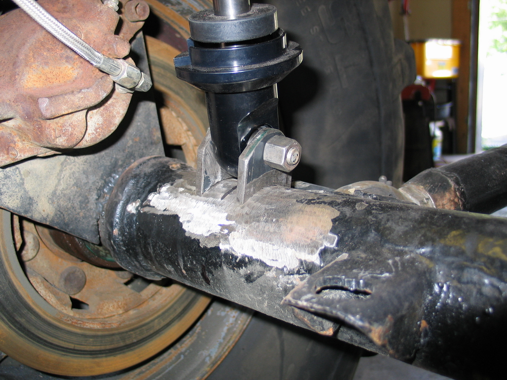 |
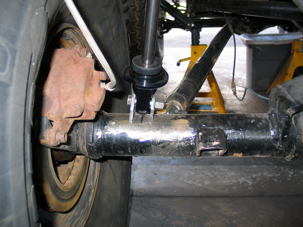
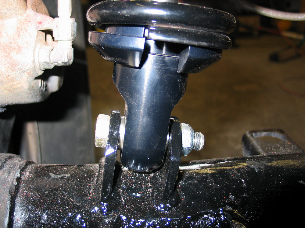
I chose to mount the lower (axle) end transverse... | ||||||||||||||||||||||||||||||||||||||||||||
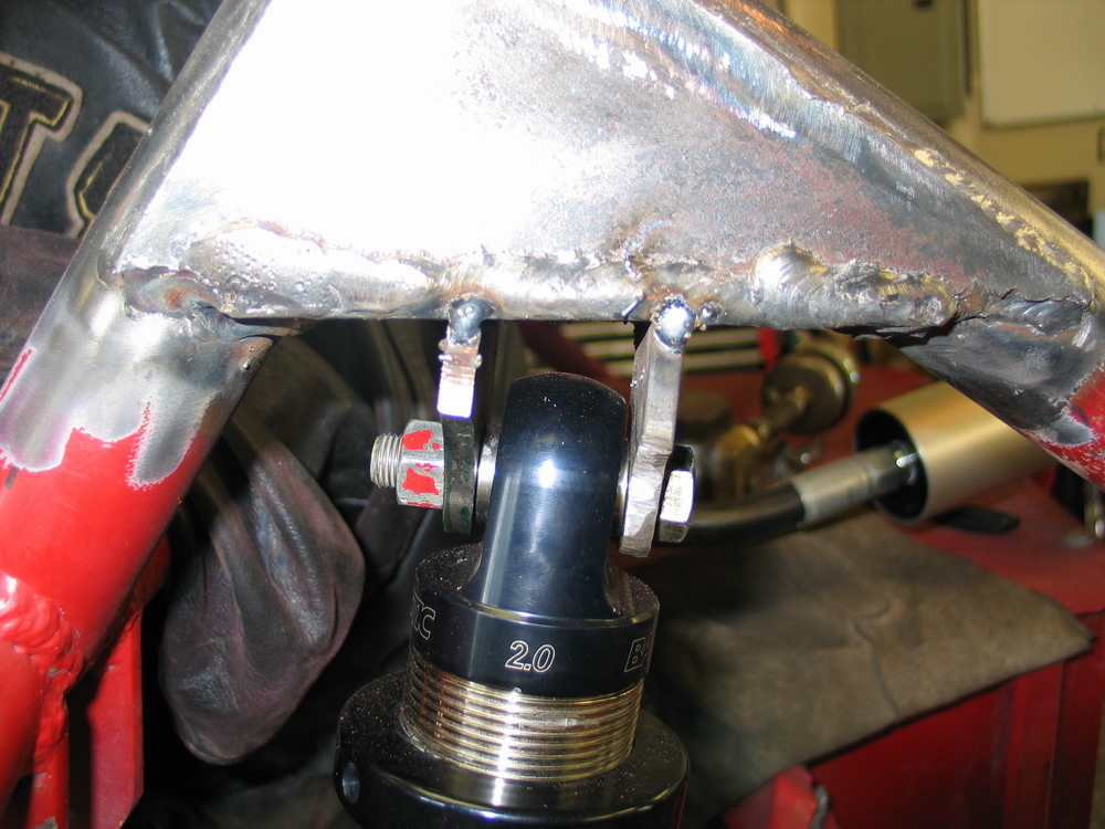 |
... and the upper end longitudinal, simply because that worked best with my particular chassis design. | ||||||||||||||||||||||||||||||||||||||||||||
 |
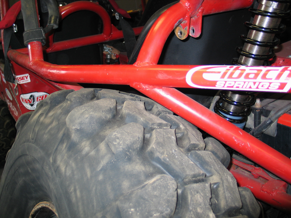
Whichever orientation you use, it's critical that you check for clearance between the tire and springs, between the springs and chassis, and for any binding throughout the full range of suspension travel - both ride travel and flex (or warp) travel. |
||||||||||||||||||||||||||||||||||||||||||||
 |
You can be creative - here I am using a piece of tube and a spring to check for chassis-to-spring clearance at full droop in flex travel. | ||||||||||||||||||||||||||||||||||||||||||||
 |
Close-up. | ||||||||||||||||||||||||||||||||||||||||||||
 |
The lower shock mount is easy - it's usually on the axle or knuckle, as far outboard as you can place it without having the tire rub the springs. | ||||||||||||||||||||||||||||||||||||||||||||
 |
The upper shock mount is usually more of a challenge and will depend on shock length, ride height, desired droop available at ride height, and chassis layout.
|
||||||||||||||||||||||||||||||||||||||||||||
 |
One method that works is to position the chassis at ride height, then set the shock to the position you want it to be in at ride height:
Then mark where the upper mount needs to be based on this. Of course, this presupposes that you have your spring length and spring rate calculations correct - a subject for a separate article! |
||||||||||||||||||||||||||||||||||||||||||||
 |
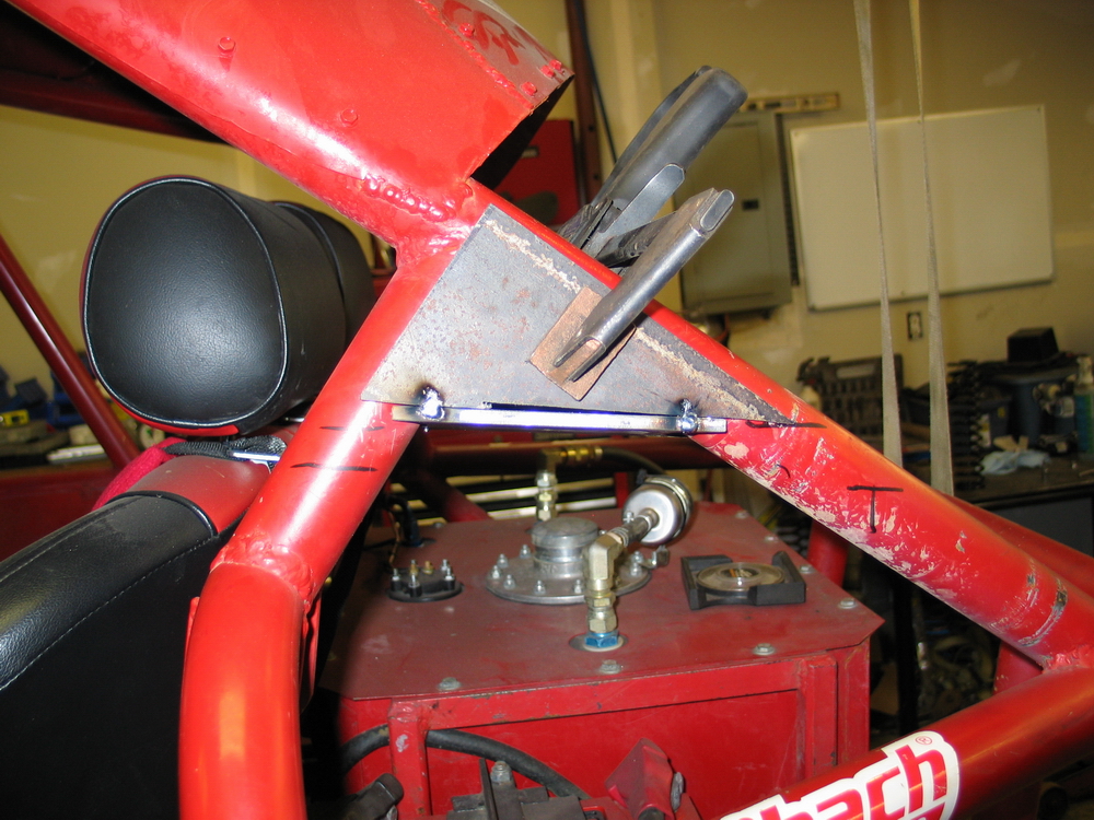
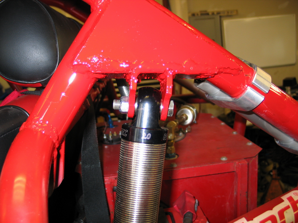
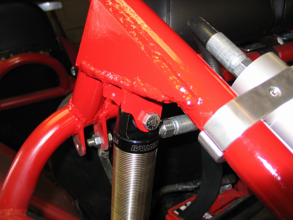
Fabricating upper shock mount. I built the upper mount at an angle to match the angle of the installed shock so that the maximum misalignment would be available from static position. That is, so that the position of the shock at static ride height wouldn't consume any of the available misalignment available in the bearings/spacers. | ||||||||||||||||||||||||||||||||||||||||||||
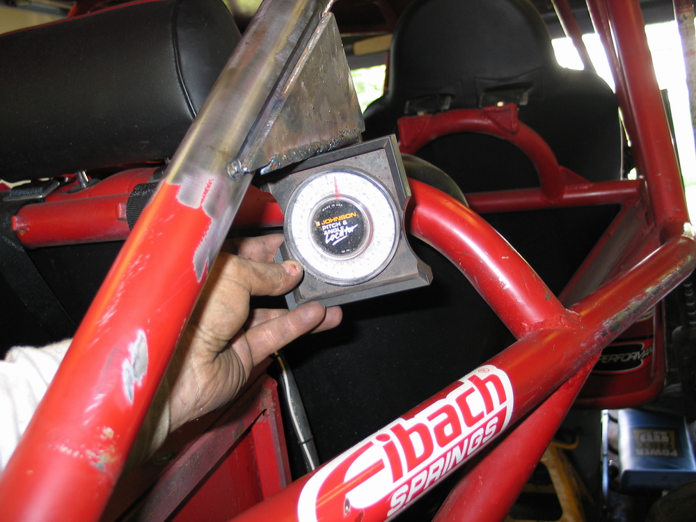 |
Checking the angle of the mount. | ||||||||||||||||||||||||||||||||||||||||||||
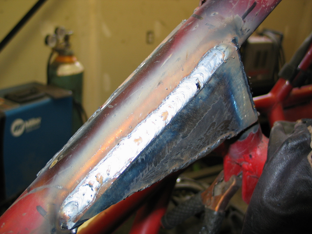 |
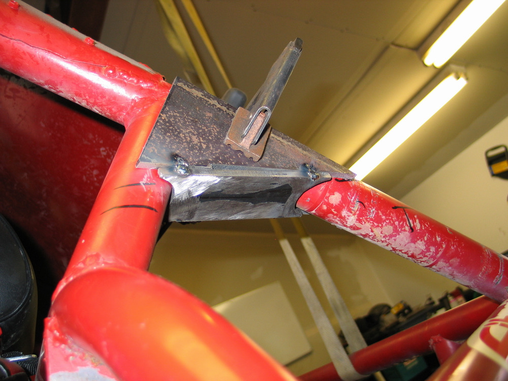
Mount welded on. See - I can lay a decent bead if I need to! ;-) |
||||||||||||||||||||||||||||||||||||||||||||
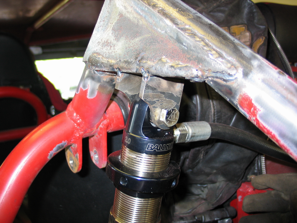 |
Upper end of shock positioned in mount. | ||||||||||||||||||||||||||||||||||||||||||||
 |
With the shock mounts tacked in place, re-check all your clearances, including tire-to-chassis clearance and adjust as required. Yes, it's a time-consuming and repetitive process, but the results are worth it. |
||||||||||||||||||||||||||||||||||||||||||||
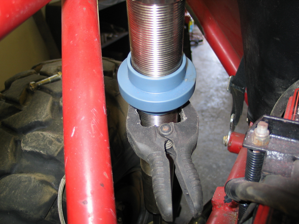 |
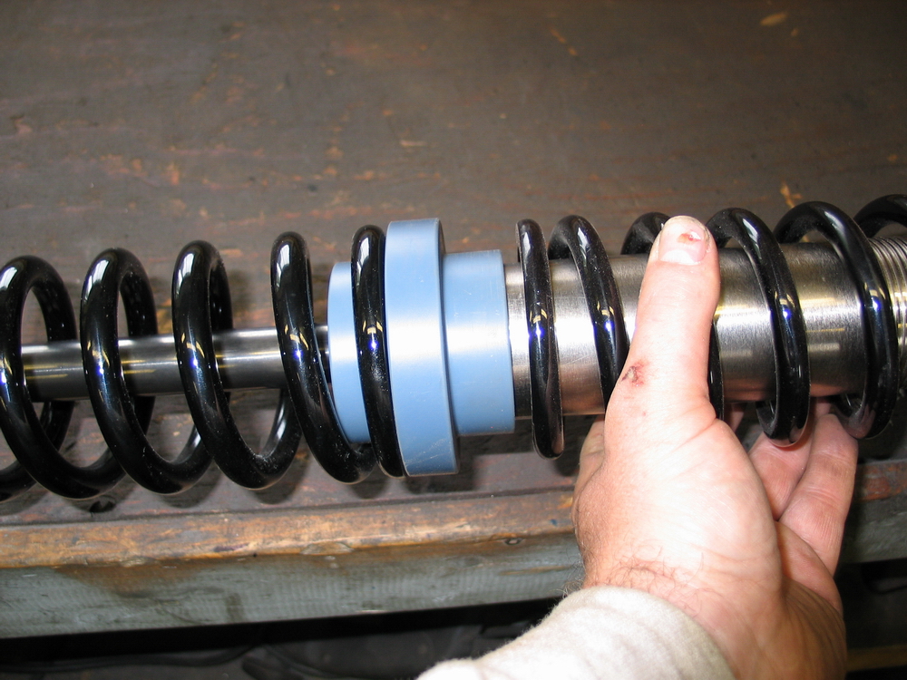
Here's a little tip: You don't have to have the springs installed on the shock to check for clearance, as the dual-rate slider has the same OD as the springs. |
||||||||||||||||||||||||||||||||||||||||||||
 |
Therefore, if there is sufficient clearance between the chassis and slider during suspension travel - there will be sufficient clearance between chassis (or tire) and spring. With the mounts built and clearances checked, it's time to assemble the springs on the shock prior to final installation of the shocks. |
||||||||||||||||||||||||||||||||||||||||||||
Installing the Springs on the Shock |
|||||||||||||||||||||||||||||||||||||||||||||
|
One of the most frustrating aspects of most coilover shocks, including the Ballistic Shocks, is that if you want to use a triple-rate setup you have to install a second slider to separate the helper coil from the tender coil. The problem is, the slider can't be installed from the bottom end of the shock as it wont go over the stop rings (obviously). And the stop rings can't be threaded off the bottom of the shock as the minor diameter of the threads is smaller than the shock body OD. |
||||||||||||||||||||||||||||||||||||||||||||
 |
That means that the triple-rate slider must be installed from the top of the shock, necessitating either the removal of the reservoir hose, or possibly even the top cap itself - either of which will allow air into the shock. Of course that means just installing a triple-rate slider means you then have to disassemble the whole shock to bleed the air out! |
||||||||||||||||||||||||||||||||||||||||||||
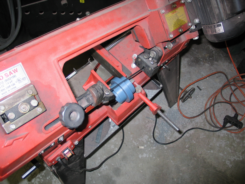 |
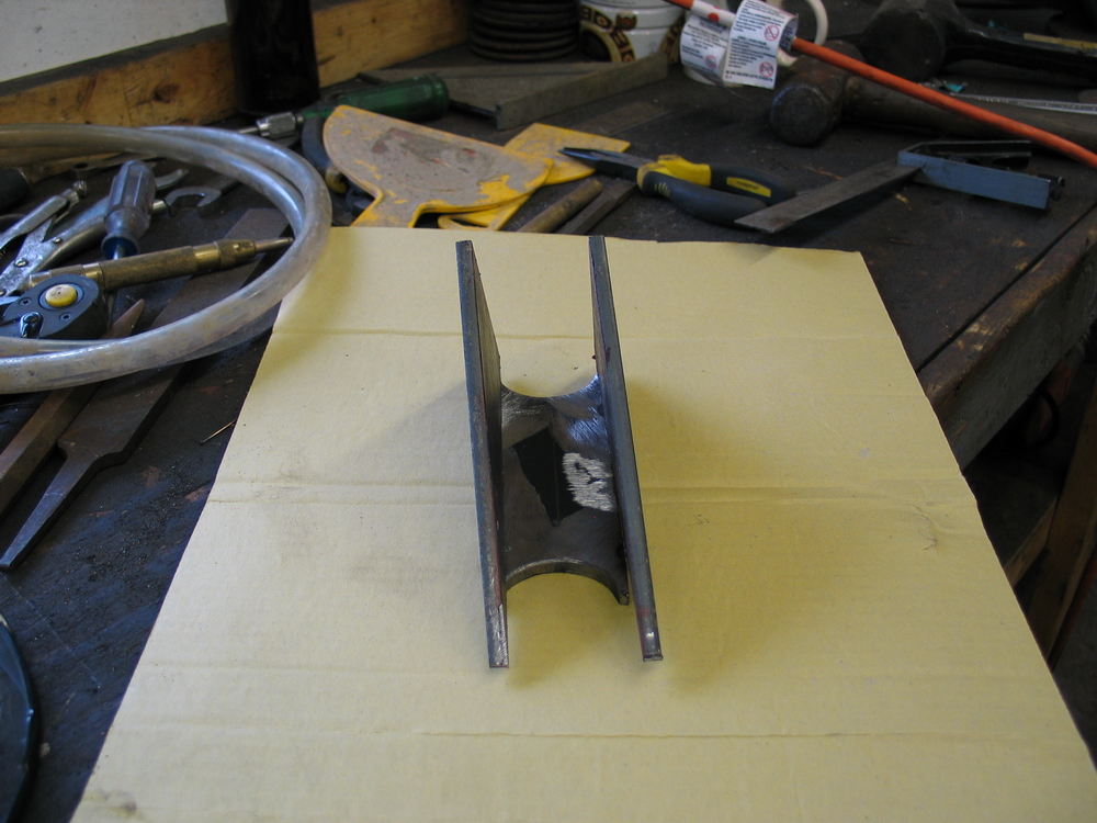
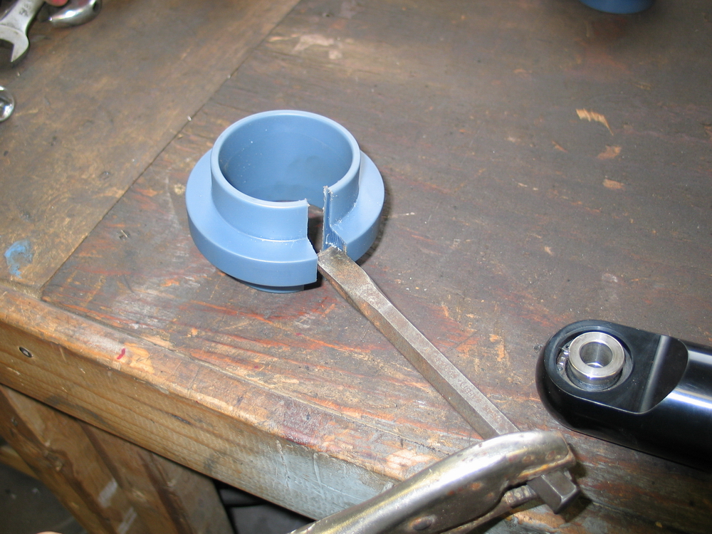
Frankly I wasn't looking forward to having to do that so i decided to try a different approach. I decided to split one side of the triple-rate slider by cutting it along its length in the bandsaw. |
||||||||||||||||||||||||||||||||||||||||||||
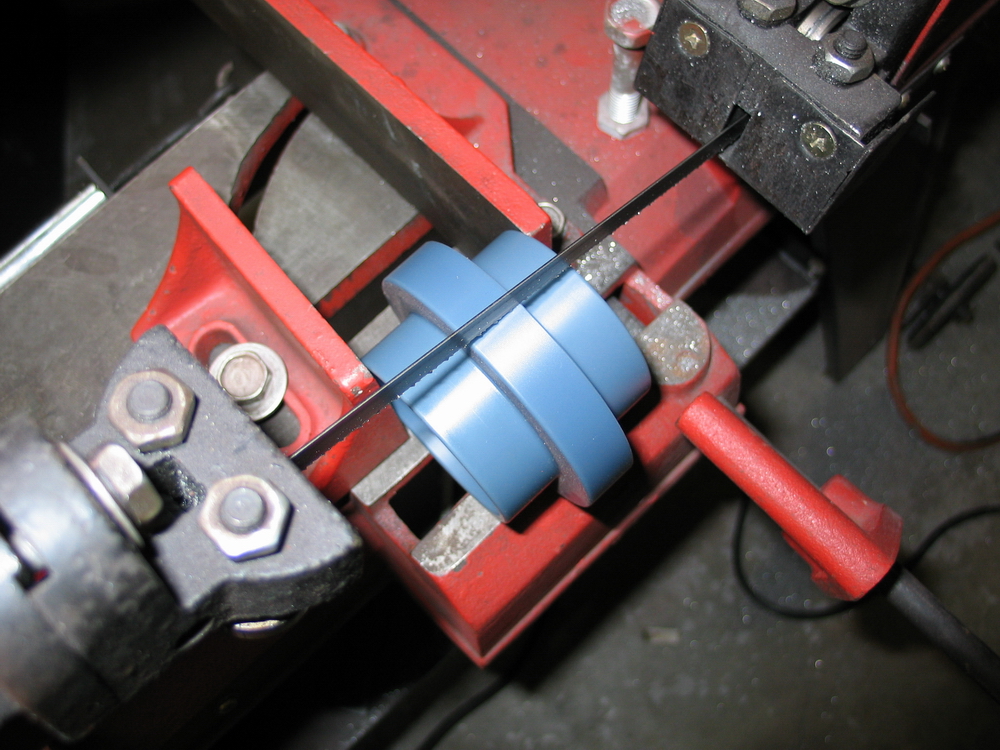 |
Only cut through one side. The idea being, that I could now ''spring open'' the slider enough to force it over the stop rings from the bottom. |
||||||||||||||||||||||||||||||||||||||||||||
 |
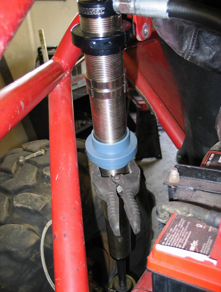
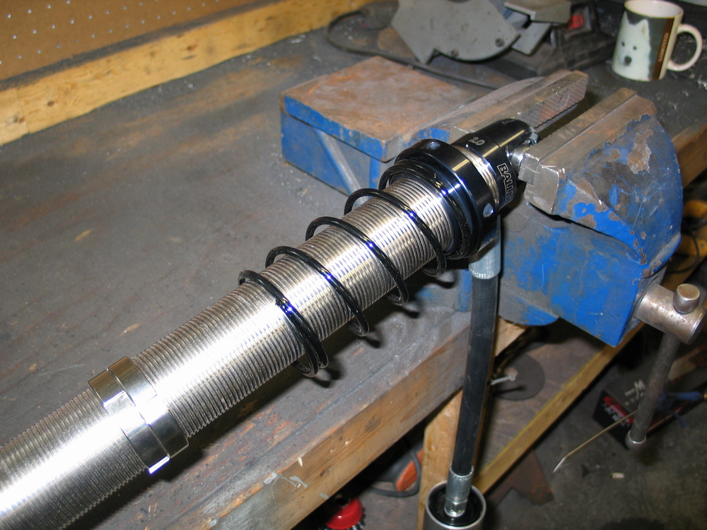
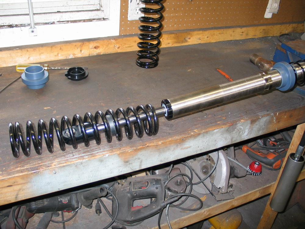
With the triple-rate slider so modified, clamp the top cap misalignment spacers in a vice and position the shock on the bench. Depending on your spring lengths, it can be helpful at this stage to run the upper spring seat all the way to the top of the shock. |
||||||||||||||||||||||||||||||||||||||||||||
 |
Slide up the rubber bumper and remove the lower spring seat. | ||||||||||||||||||||||||||||||||||||||||||||
 |
Slide the unmodified dual-rate slider off the shock. | ||||||||||||||||||||||||||||||||||||||||||||
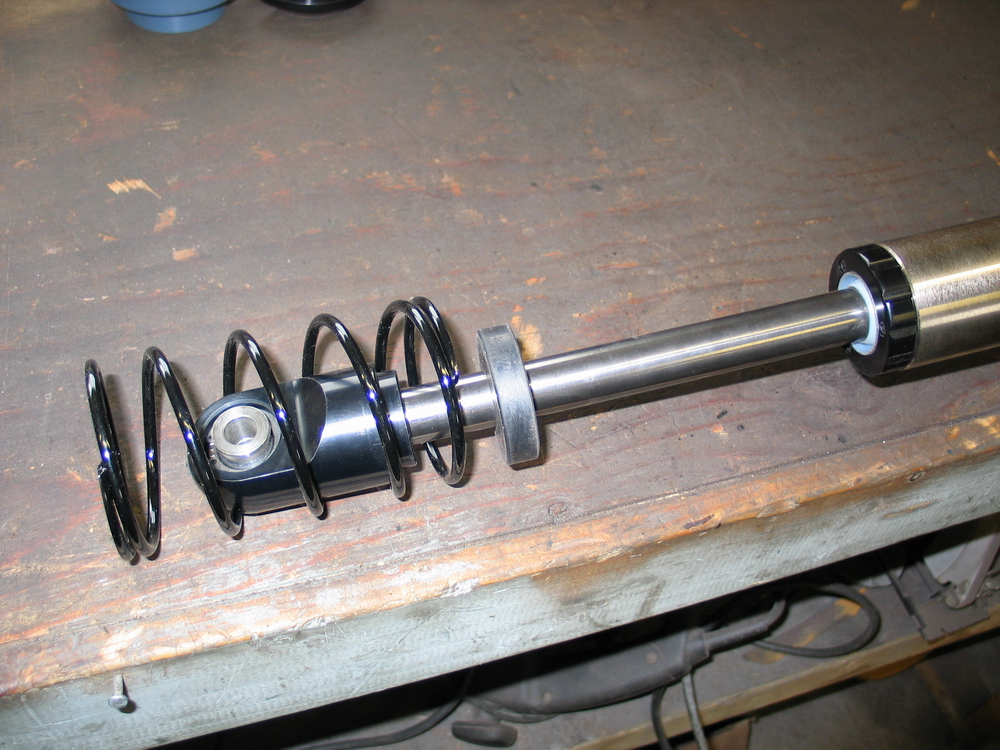 |
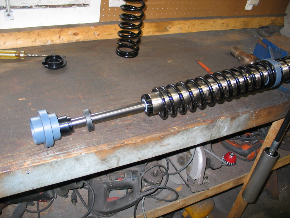
Slide the helper spring over the lower end of the shock... | ||||||||||||||||||||||||||||||||||||||||||||
 |
... and into place against the upper spring seat at the top of the shock. | ||||||||||||||||||||||||||||||||||||||||||||
 |
I then used a small chisel and a pair of vice grips to open up the triple-rate slider a bit. | ||||||||||||||||||||||||||||||||||||||||||||
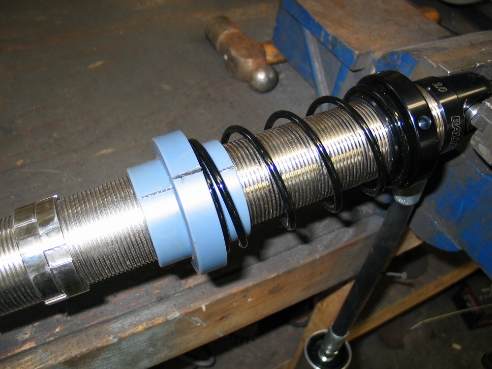 |
This allowed me just enough extra space to get the triple-rate slider over the stop rings and up against the bottom of the helper spring. It took a bit of careful persuasion but worked a treat. |
||||||||||||||||||||||||||||||||||||||||||||
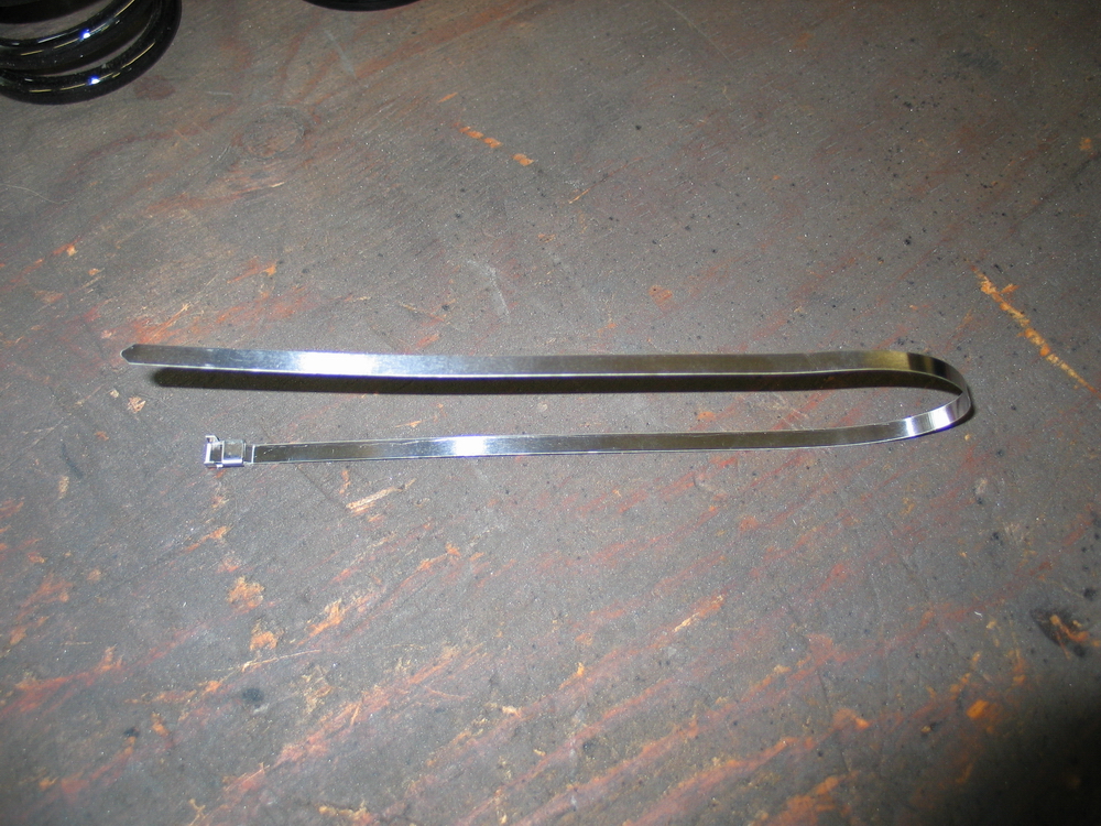 |
My original intent was to then tightly wrap a CV-band clamp around the triple-rate slider one it was in place, but frankly ran out of time (OK, I forgot to) before my first run on the new shocks and, after several hard runs, have found that there are no ill effects to having a small slit in the triple-rate slider. In other words, by modifying the triple-rate slider, I hugely simplified the task of installing it and the springs with no less of functionality. |
||||||||||||||||||||||||||||||||||||||||||||
|
Now I'd just like to see a company design and market a triple-rate slider that comes with a split and some sort of retention device like a pinch bolt - similar to the design of the Ballistic upper spring seat. | ||||||||||||||||||||||||||||||||||||||||||||
 |
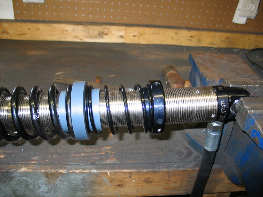
With the helper spring and triple-rate slider in place, slide the tender spring on the shock... | ||||||||||||||||||||||||||||||||||||||||||||
 |
...followed by the dual-rate slider... | ||||||||||||||||||||||||||||||||||||||||||||
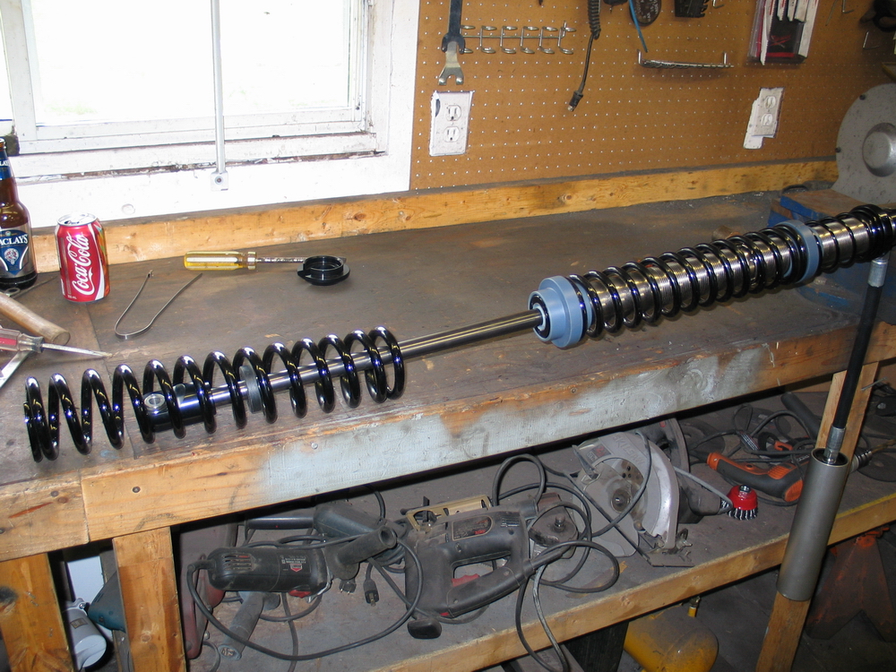 |
...and finally the main spring. | ||||||||||||||||||||||||||||||||||||||||||||
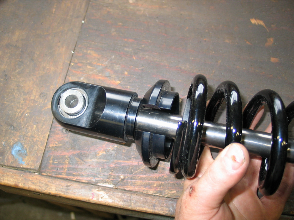 |
Slip the lower spring seat over the shock shaft... | ||||||||||||||||||||||||||||||||||||||||||||
 |
... and secure in place with the rubber bumper. Note that the rubber bumper only needs to hold the lower spring seat in place when there is no load on the springs. With any force on the springs (including that exerted by the helper spring) the springs themselves hold the lower spring seat in place. |
||||||||||||||||||||||||||||||||||||||||||||
 |
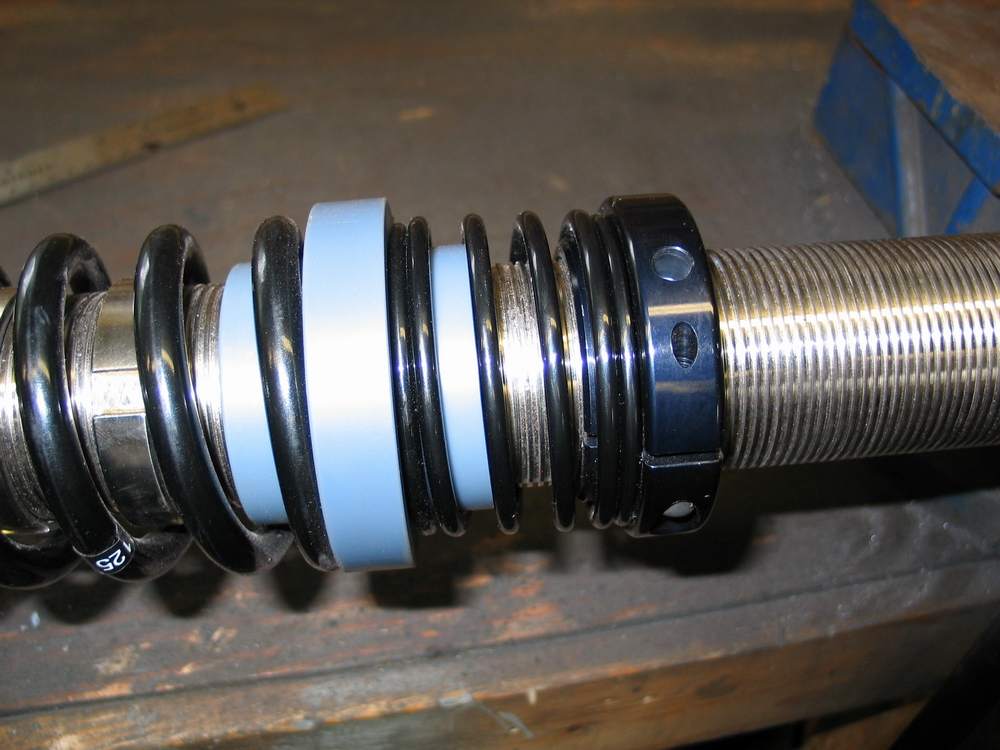
Where the main and tender coils meet at the dual-rate slider, orient the ends of the two coils so that the very ends of the springs are opposite one-another where they seat against the slider. | ||||||||||||||||||||||||||||||||||||||||||||
 |
You can now position the top spring seat where required to get the spring length / preload required for your setup. | ||||||||||||||||||||||||||||||||||||||||||||
 |
This shows the initial position of my upper spring seat. |
||||||||||||||||||||||||||||||||||||||||||||
 |
The final step is to charge the shock reservoir with 100-200 psi of nitrogen. | ||||||||||||||||||||||||||||||||||||||||||||
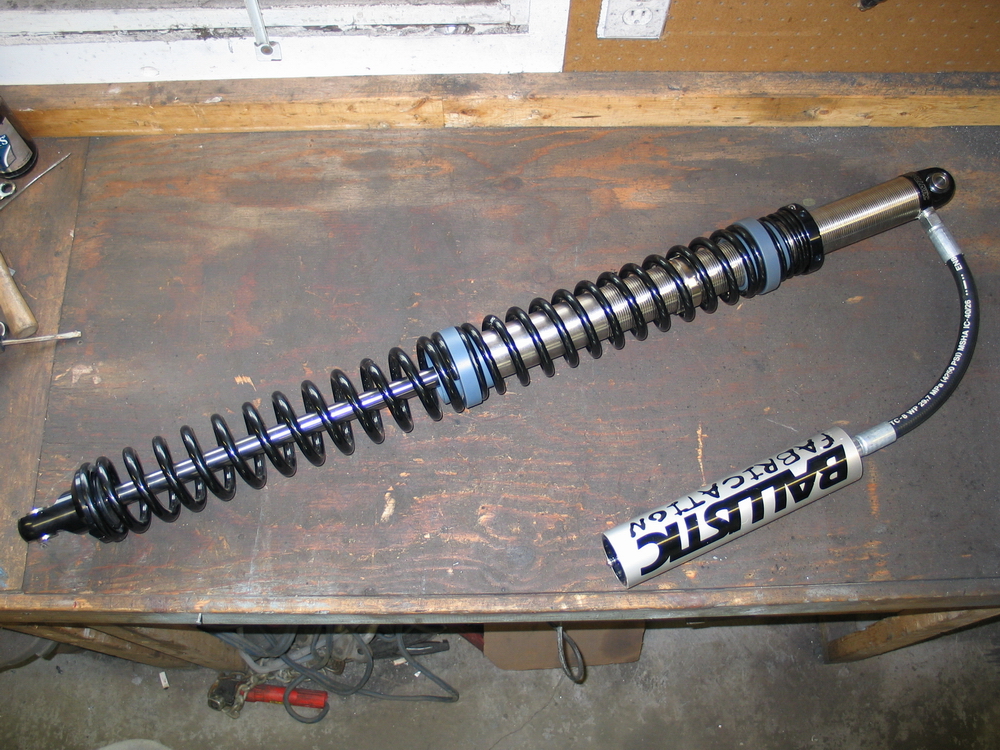 |
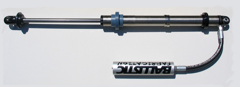
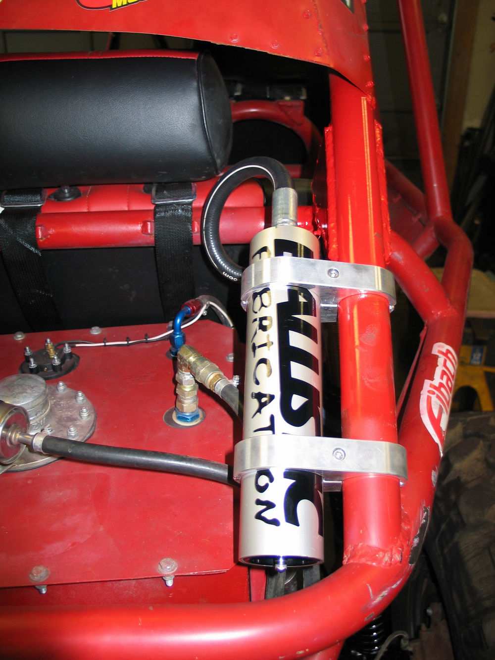
Fully assembled shock ready for final installation. Note that the heavy-duty reservoir hose on the Ballistic shocks is fairly short and stiff, so careful attention must be paid to reservoir mounting location. Of course you want to keep the reservoirs away from heat sources such as exhaust and engine and protected from damage in the event of a flop or roll. |
||||||||||||||||||||||||||||||||||||||||||||
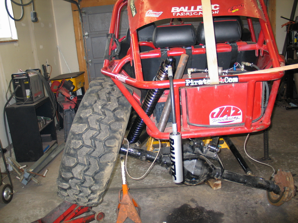
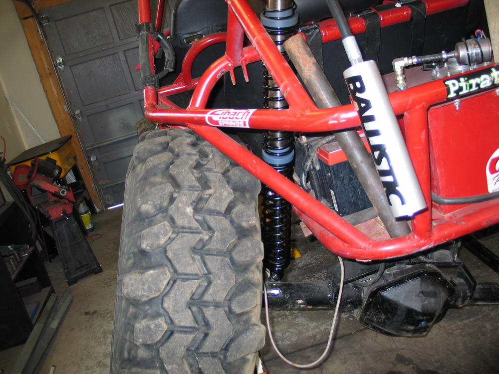
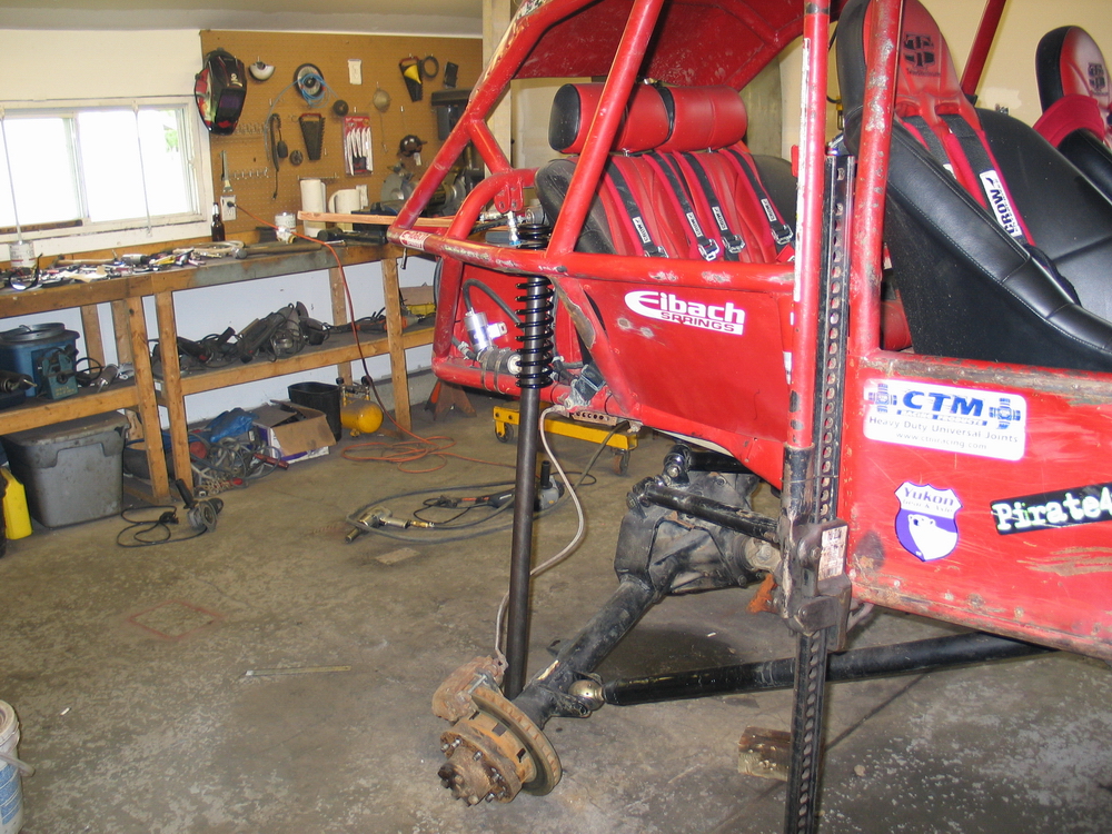
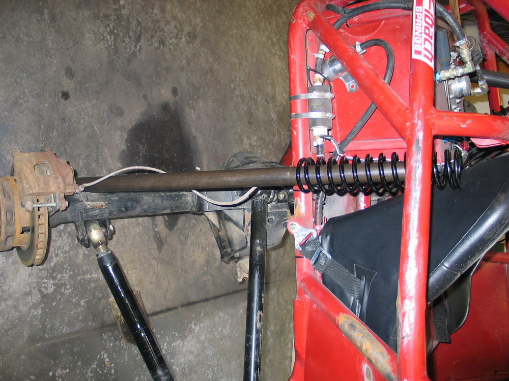
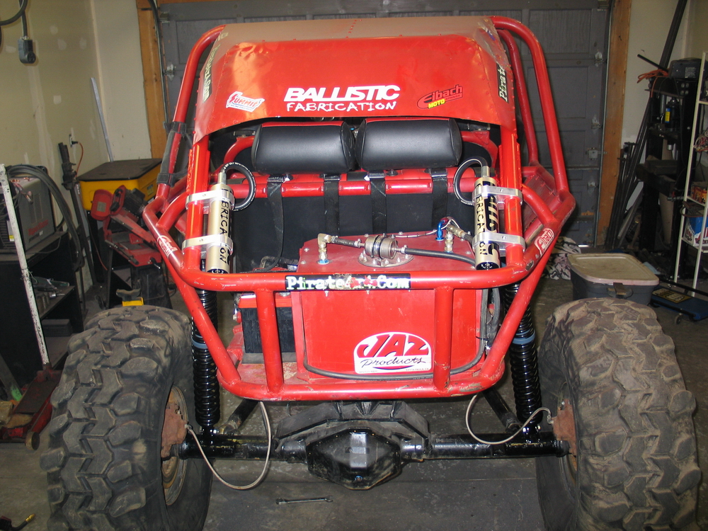
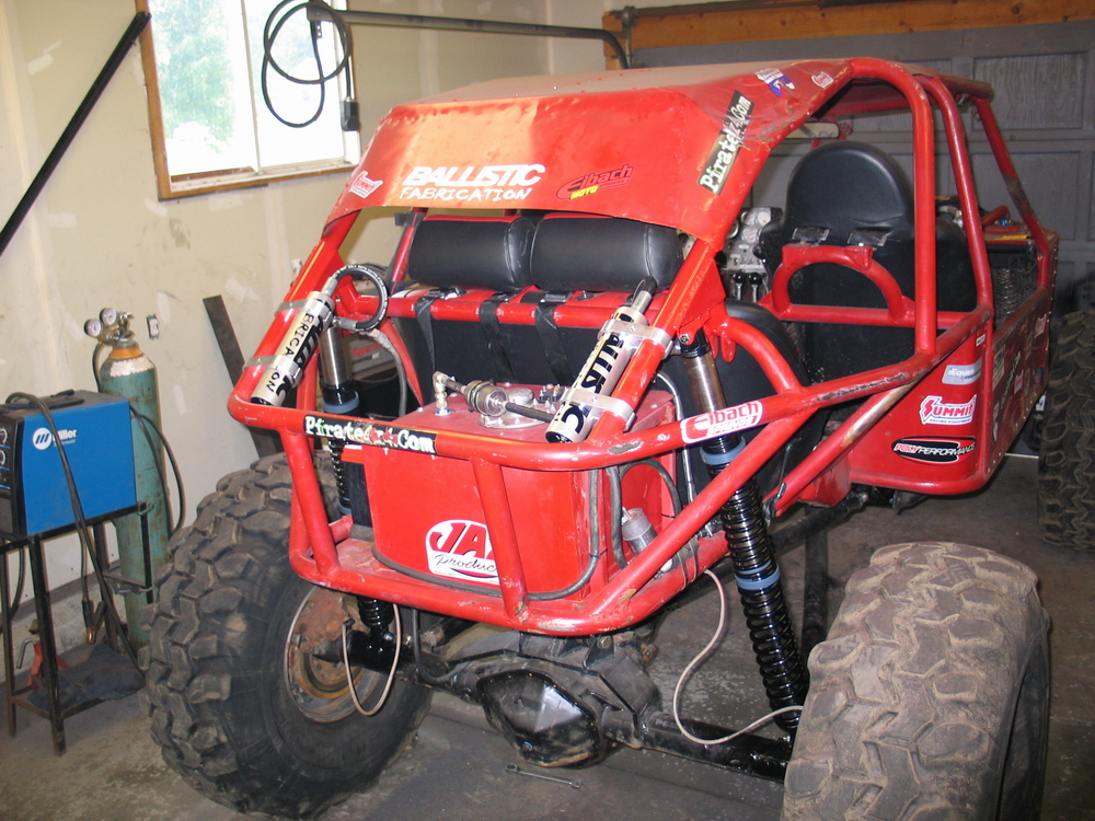
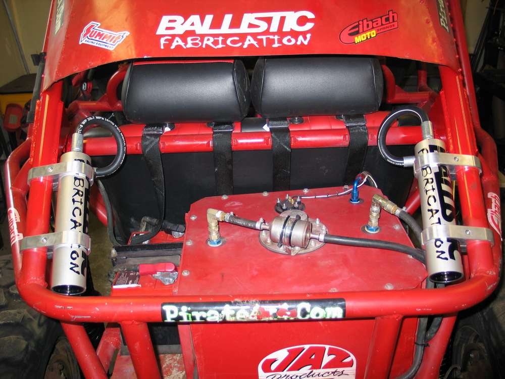
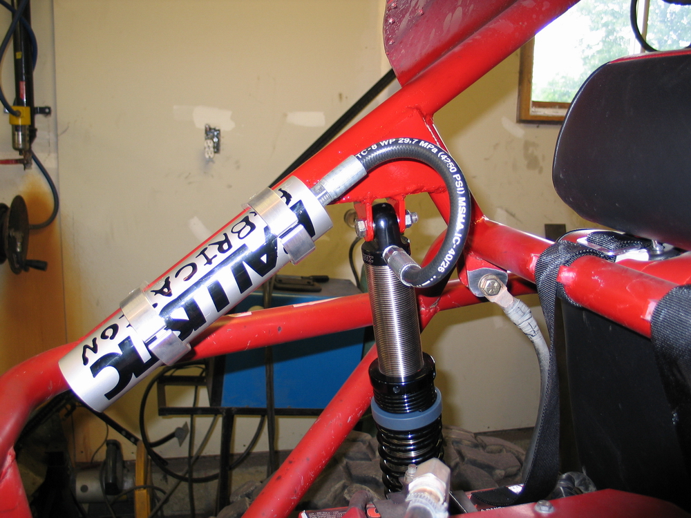
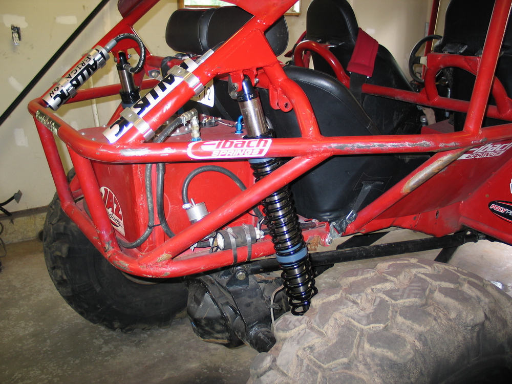
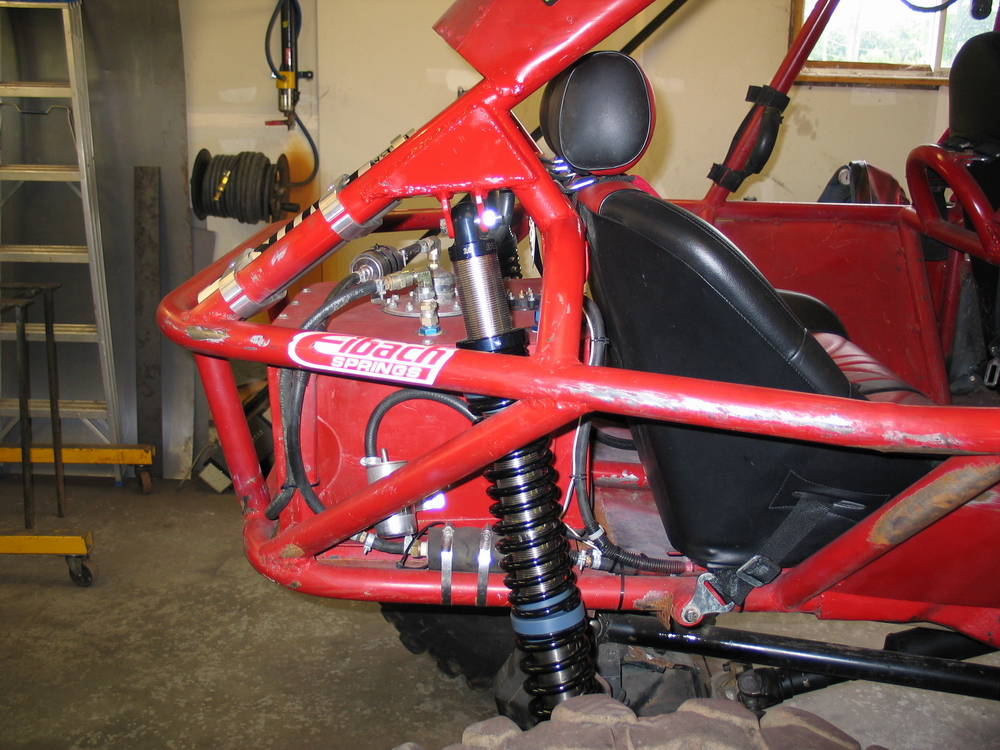
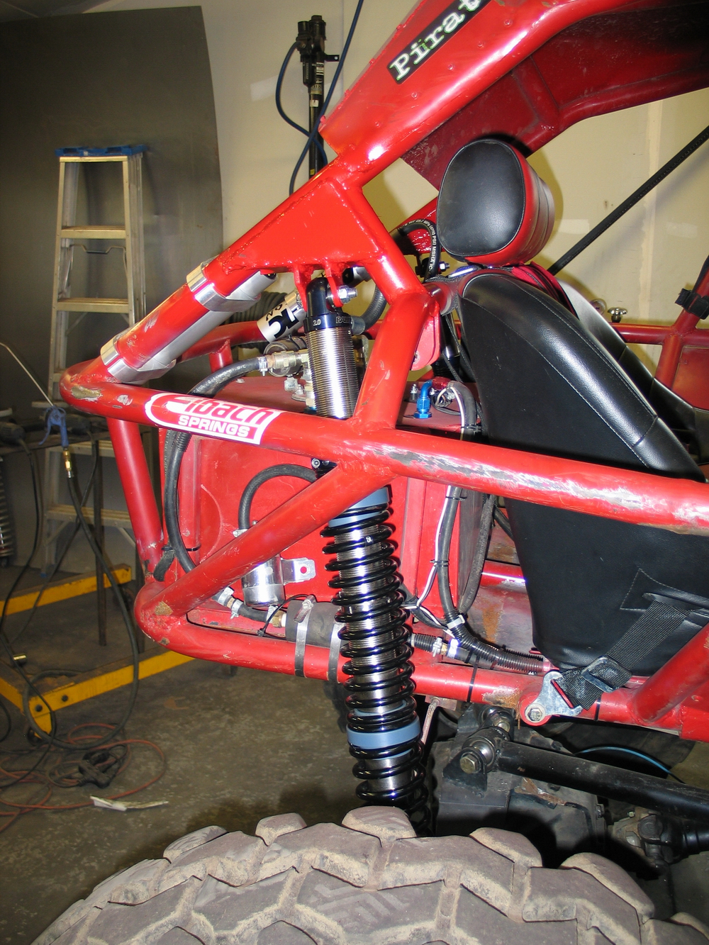
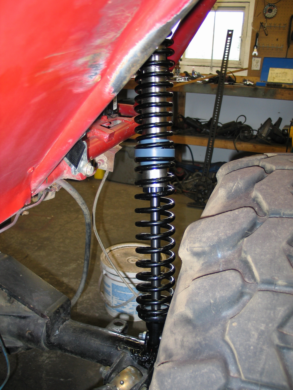
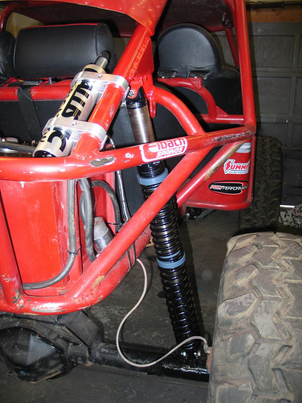
Final InstallationA gallery of the installed shocks.
|
|||||||||||||||||||||||||||||||||||||||||||||
Inside the shocksDespite what I said earlier about not wanting to tear into brand-new shocks right away, what BillaVista review would be complete without taking stuff apart! Sheesh - the things I do for you, my dear and loyal readers! |
|||||||||||||||||||||||||||||||||||||||||||||
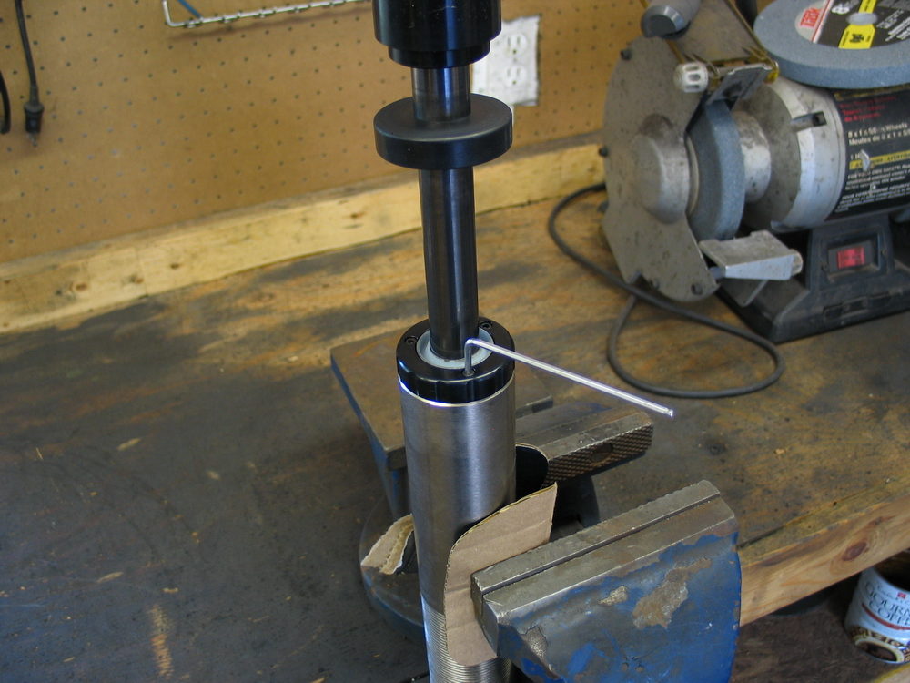 |
To disassemble the shocks, clamp the shock body vertically in a vice with the rod-end up. Use something soft between the jaws of the vice and the shock body to avoid damaging the shock. Remove the three small allen-head cap screws... |
||||||||||||||||||||||||||||||||||||||||||||
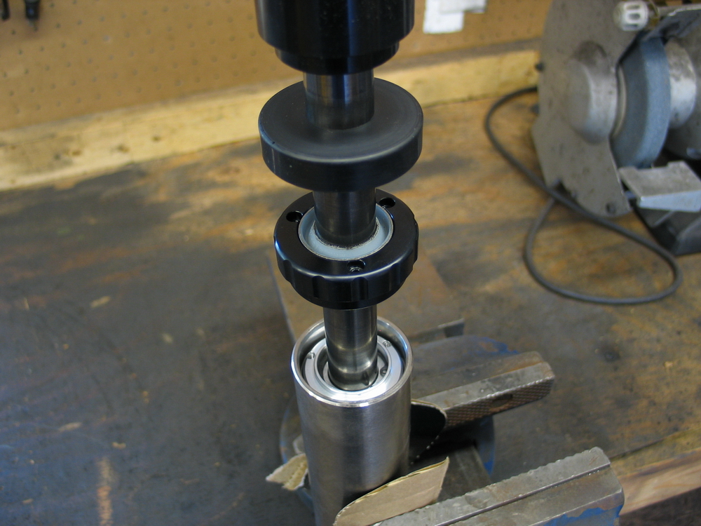 |
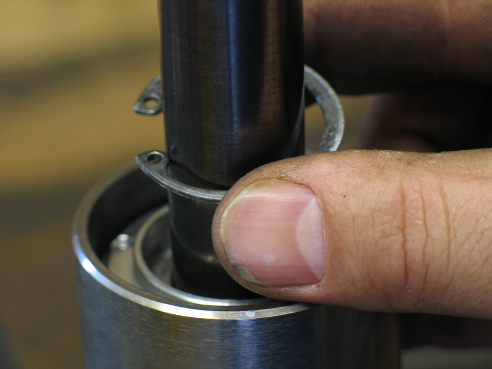
... and slide the bearing cap up the shaft. | ||||||||||||||||||||||||||||||||||||||||||||
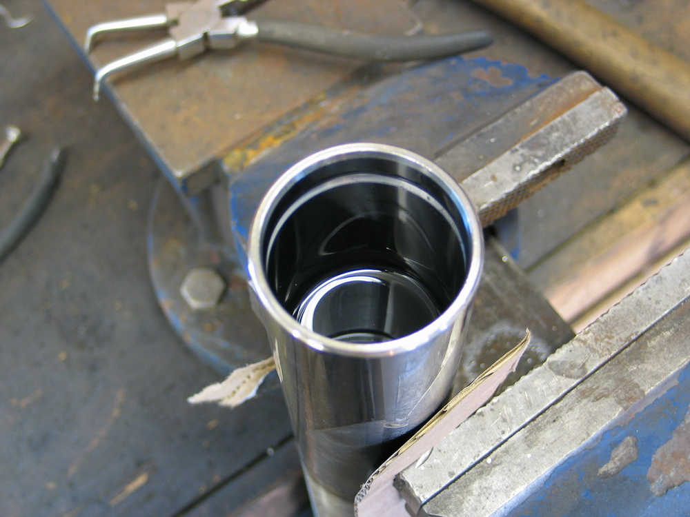
 |
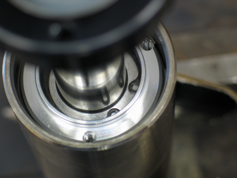
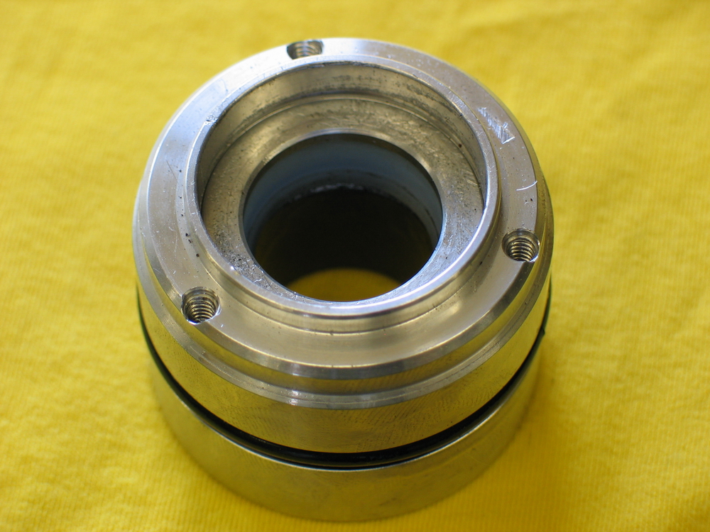
You can now see the bearing (aka rod guide or seal housing) inside the body of the shock. | ||||||||||||||||||||||||||||||||||||||||||||
 |
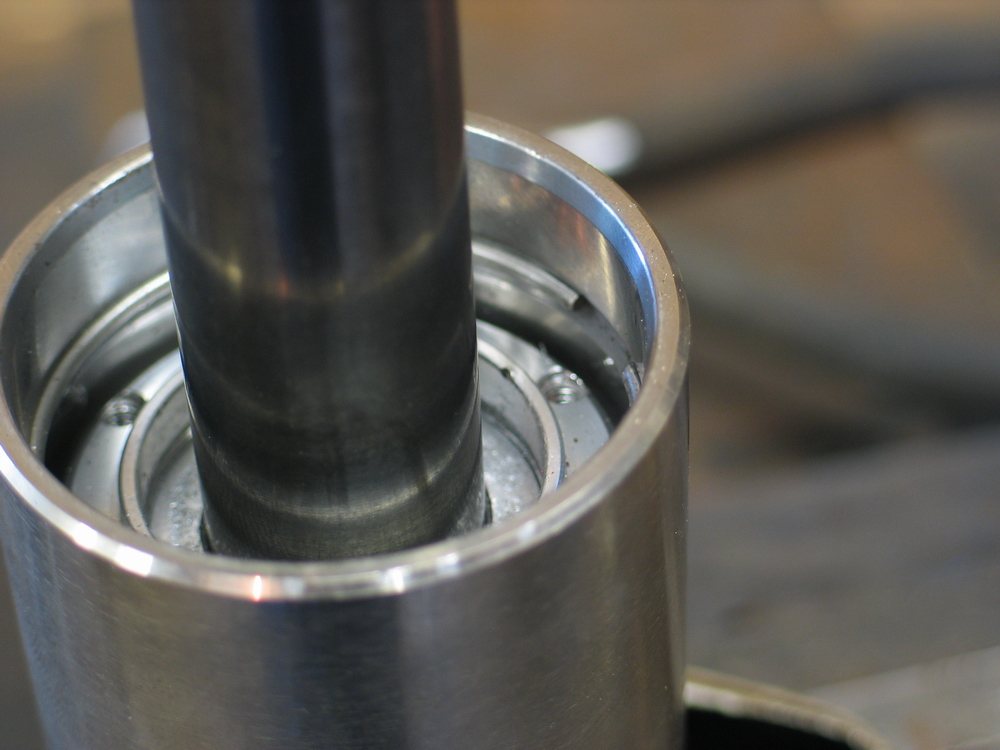
You must now remove the internal snap-ring. Work carefully with a quality pair of snap-ring pliers and a small pick to avoid scratching the polished surface of the shaft. | ||||||||||||||||||||||||||||||||||||||||||||
 |
Slide the snap-ring up the shaft and out of the way. | ||||||||||||||||||||||||||||||||||||||||||||
 |
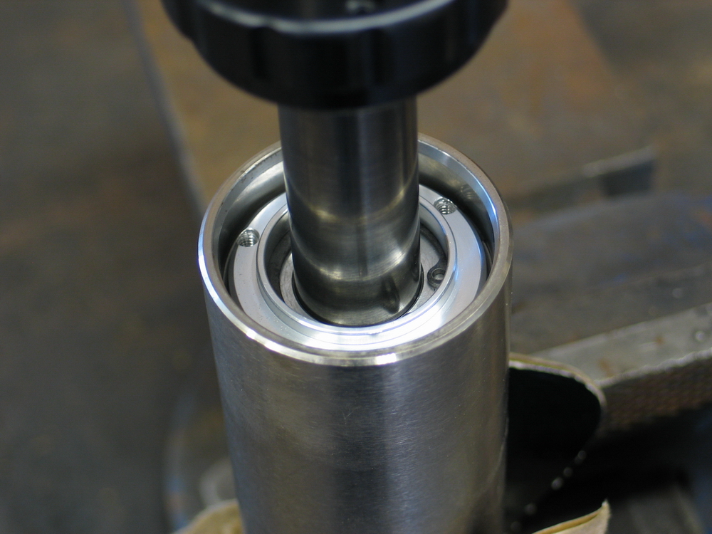
Then carefully tap the bearing into the shock body with a soft brass punch or wooden dowel, exposing the circular retaining ring. Carefully pry the retaining ring from its groove and slide it off the shaft. Carefully remove the rod and piston from the shock by pulling up on the shock shaft and gently rocking it back and forth. Be careful not to spill any of the shock oil as you remove the rod and piston. |
||||||||||||||||||||||||||||||||||||||||||||
 |
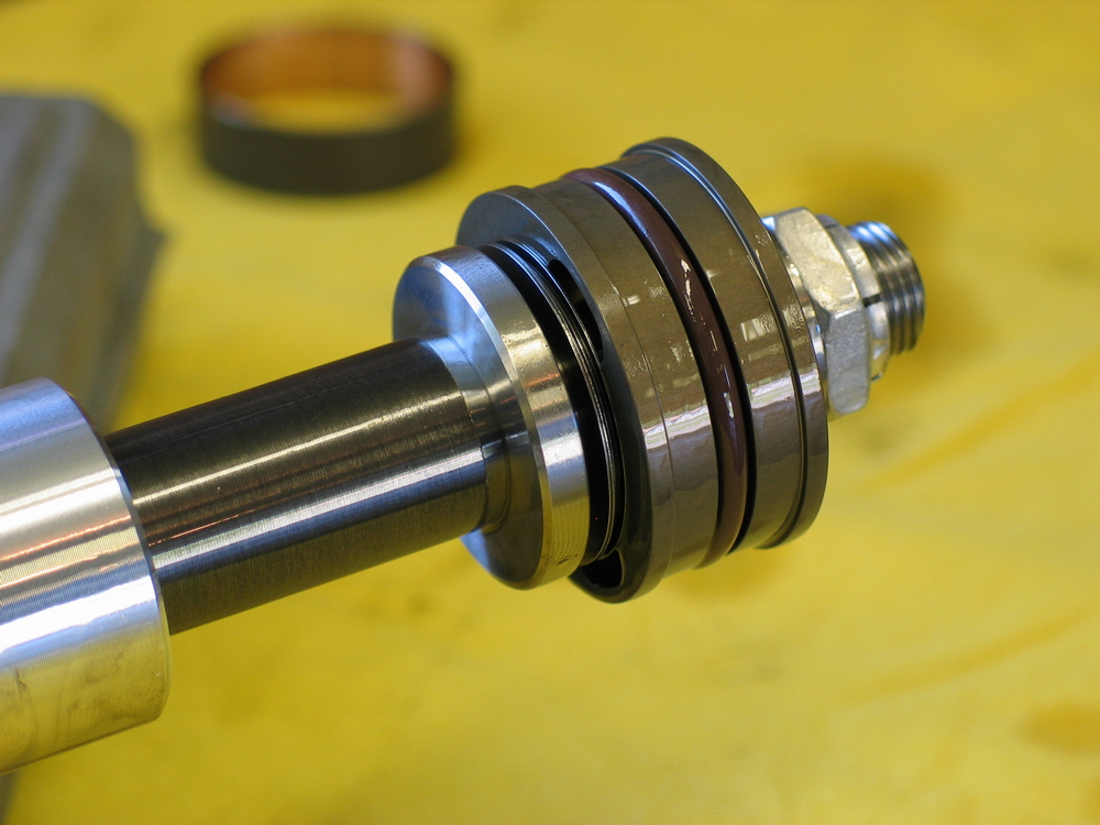
You can now lay the rod and piston on the bench and perform any necessary work such as replacing the teflon wear band, O-ring and seals, or re-valving the shock. |
||||||||||||||||||||||||||||||||||||||||||||
 |
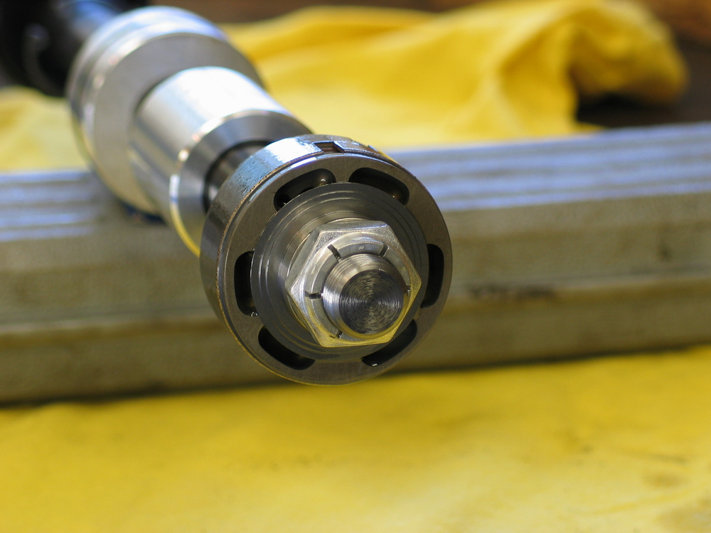
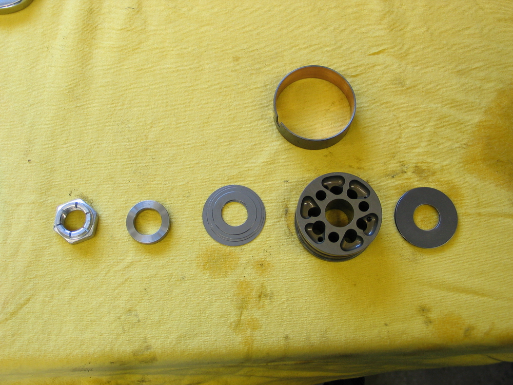
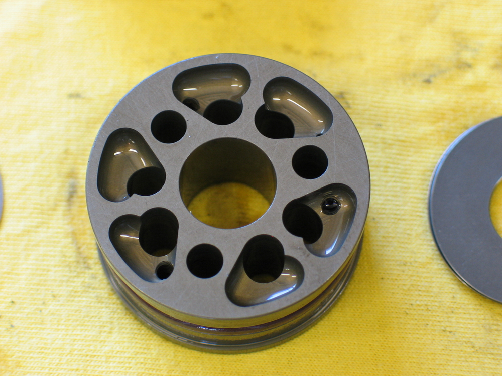
Here's a closer look at the business end of the shock. | ||||||||||||||||||||||||||||||||||||||||||||
 |
From left-to-right:
|
||||||||||||||||||||||||||||||||||||||||||||
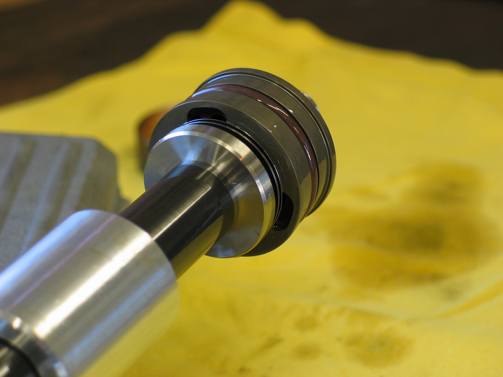
 |
The compression side of the piston. | ||||||||||||||||||||||||||||||||||||||||||||
 |
Side shot of piston. Note teflon wear band has been removed from piston. |
||||||||||||||||||||||||||||||||||||||||||||
 |
Rebound side of piston. | ||||||||||||||||||||||||||||||||||||||||||||
 |
The Ballistic Shocks ship with Shell brand, 10 weight, anti wear hydraulic fluid with high viscosity index 158. |
||||||||||||||||||||||||||||||||||||||||||||
 |
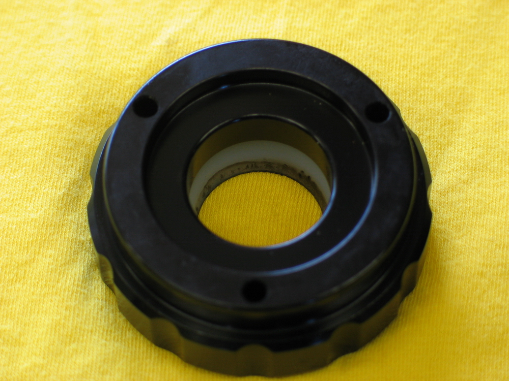
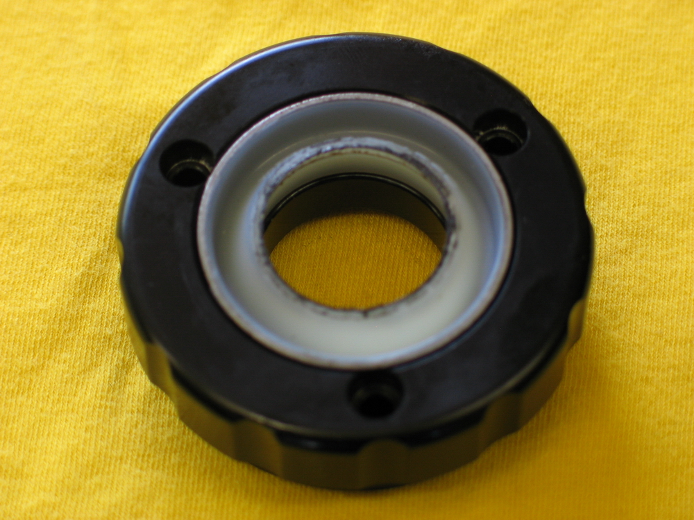
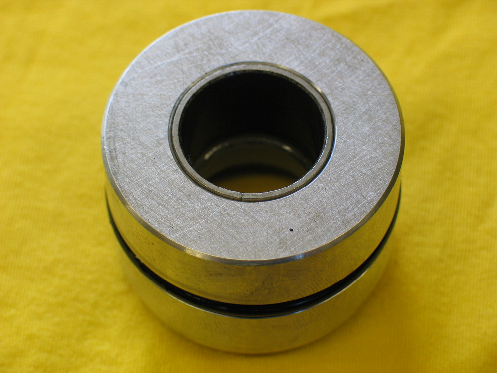
Close up of the bearing (aka the rod or shaft guide) and the primary O-ring seal. | ||||||||||||||||||||||||||||||||||||||||||||
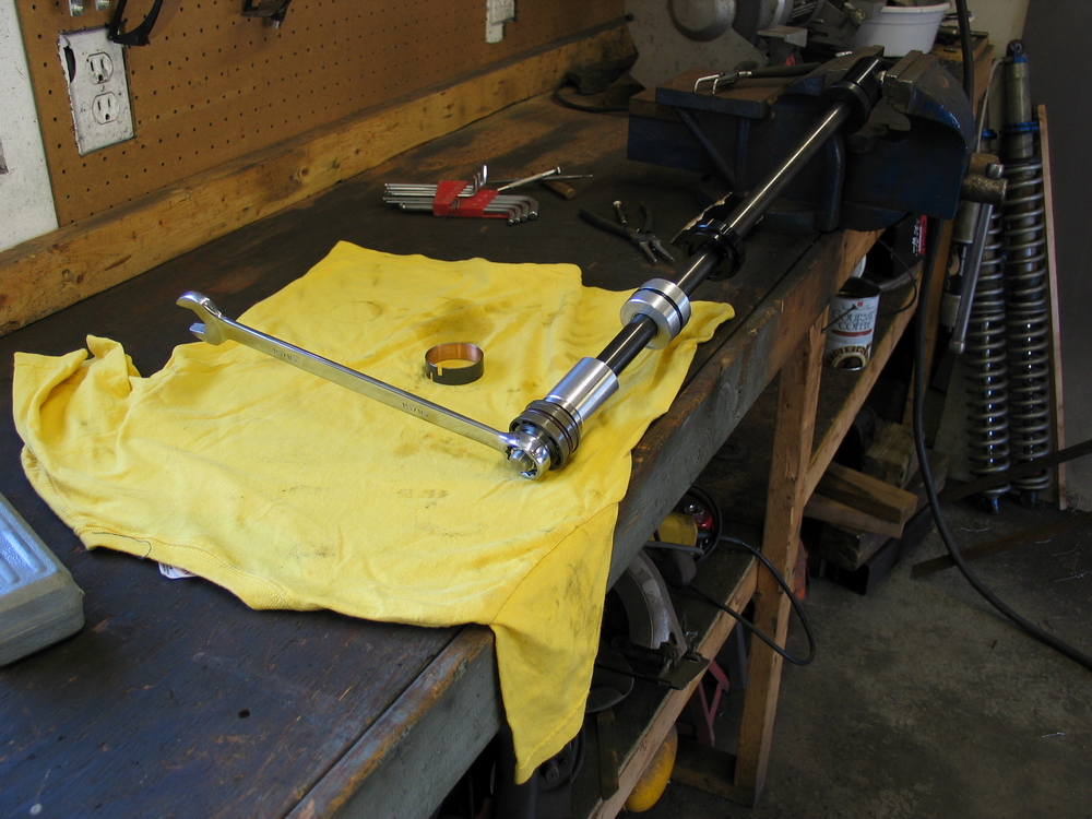 |
To disassemble the shaft components (as you would to re-valve the shock), proceed as follows: Clamp the rod end spacers firmly in a vice and support the shaft on a CLEAN workbench. |
||||||||||||||||||||||||||||||||||||||||||||
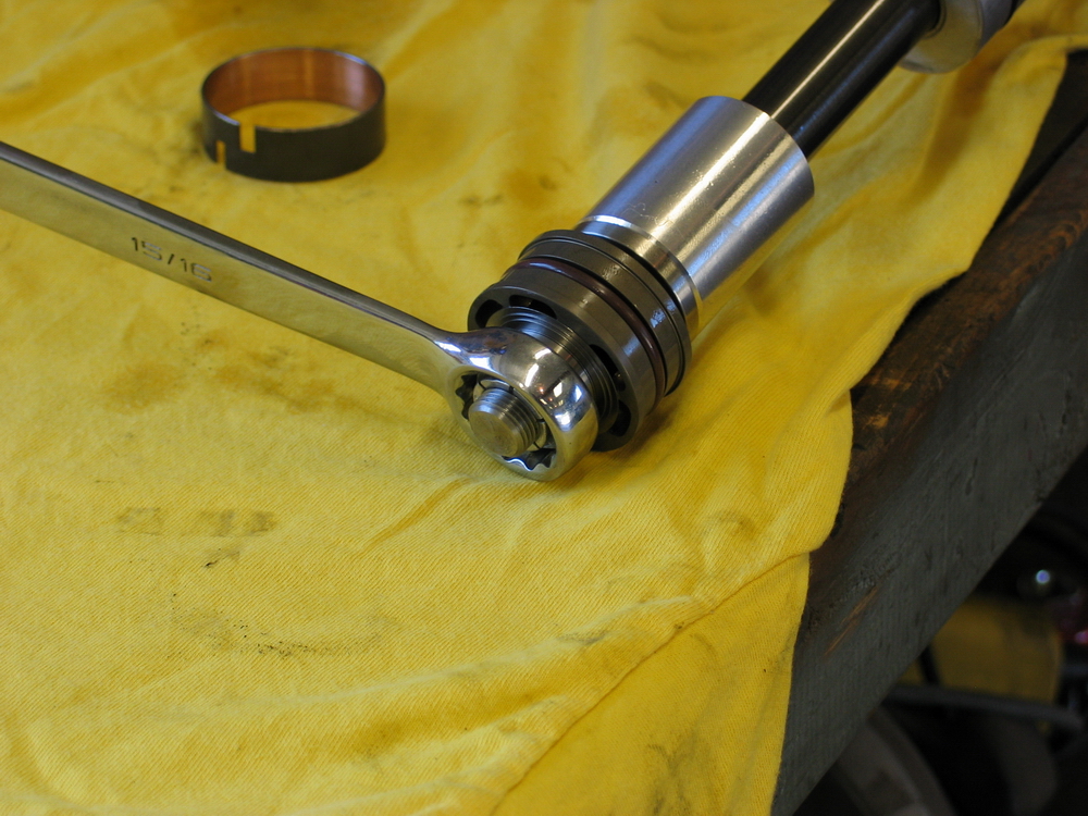 |
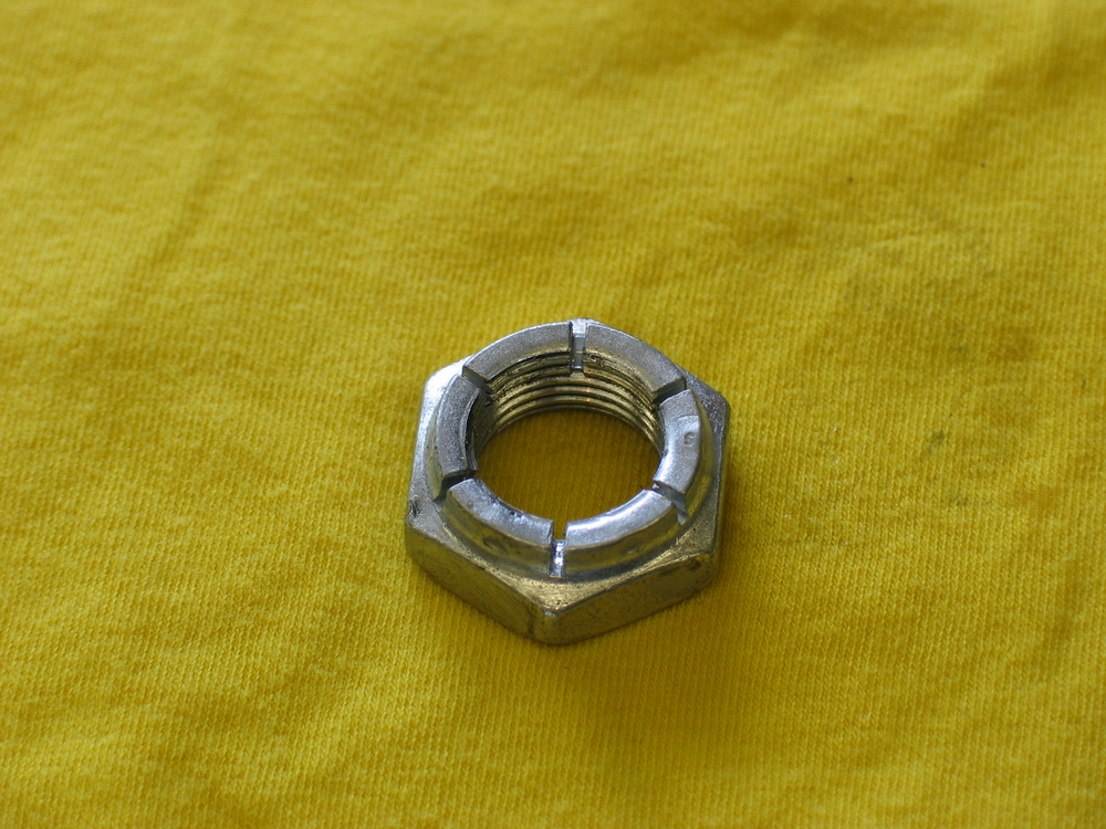
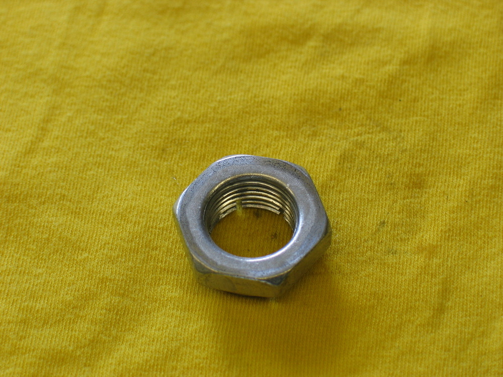
Loosen the locknut. | ||||||||||||||||||||||||||||||||||||||||||||
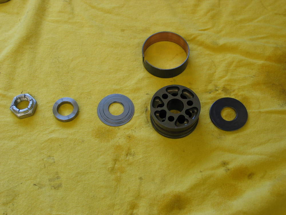 |
Slide off and carefully lay out the individual components. Pay attention too and make careful note of their orientation as they com off the shaft. The system that works well for me is: to take each piece off one at a time and set it down with the side that goes on the shaft first (i.e. the side of the component that faces away from the shock cylinder) touching the workbench. That way, when I reassemble the shaft, I pick each piece up, and the side that was down, touching the bench, is the side that goes on the shaft first. |
||||||||||||||||||||||||||||||||||||||||||||
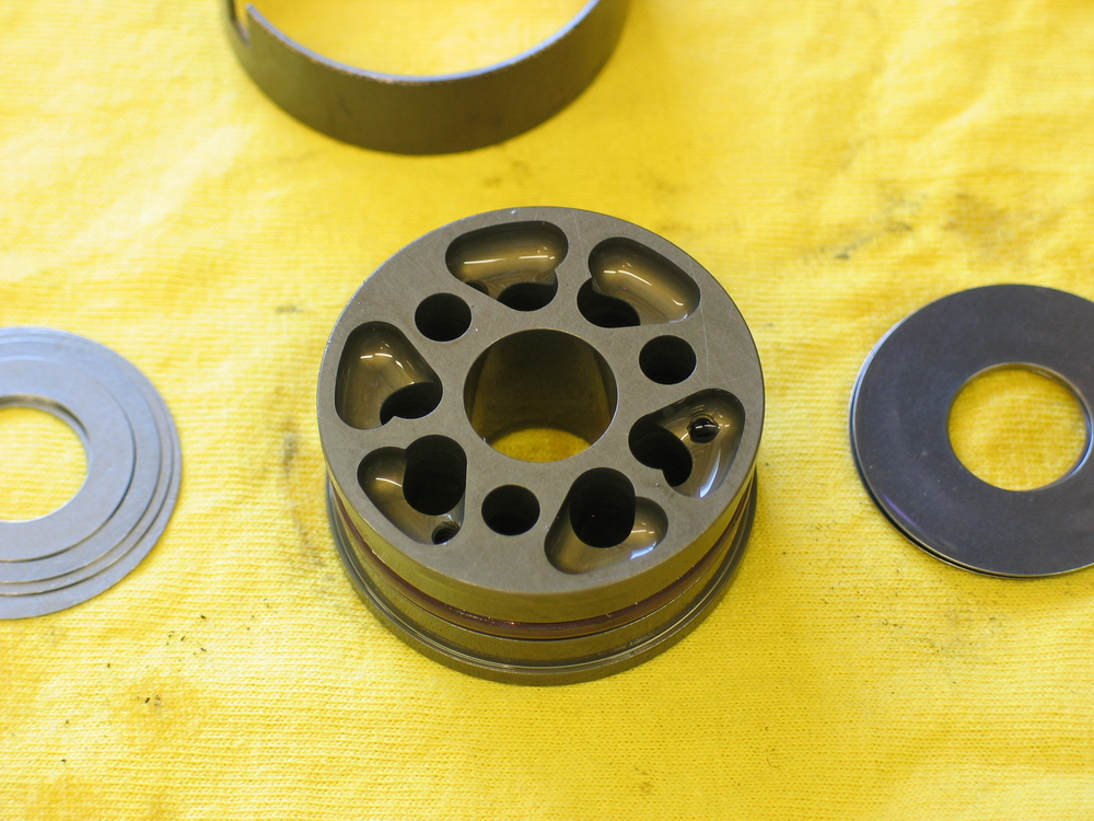 |
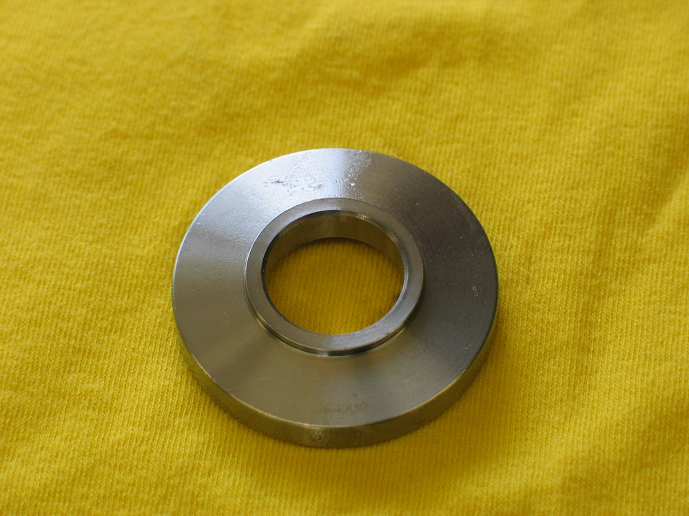
Bare piston | ||||||||||||||||||||||||||||||||||||||||||||
 |
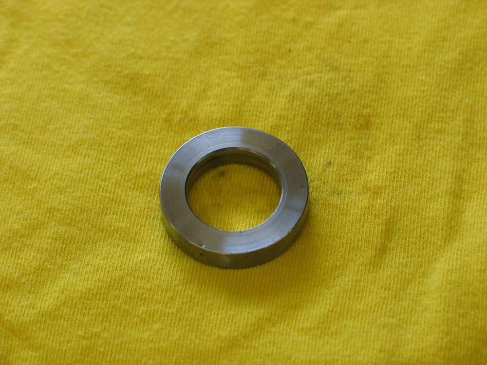
Dimensions +/- 0.02"
|
||||||||||||||||||||||||||||||||||||||||||||
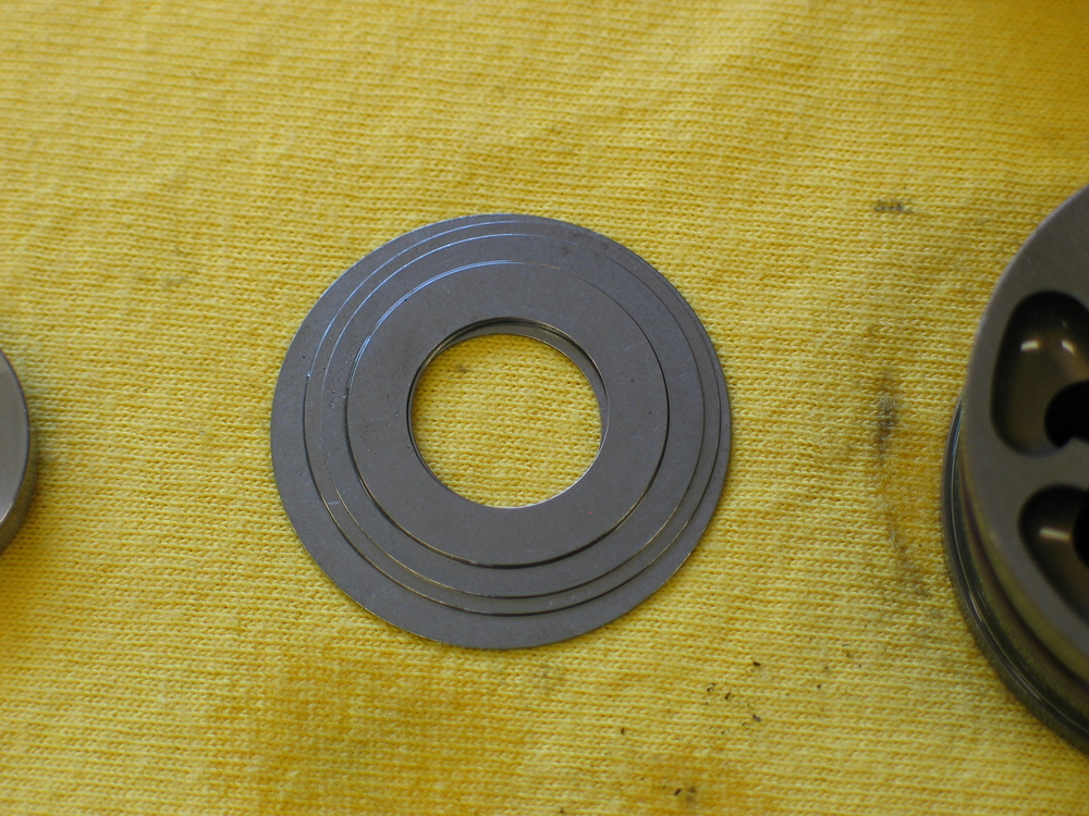 |
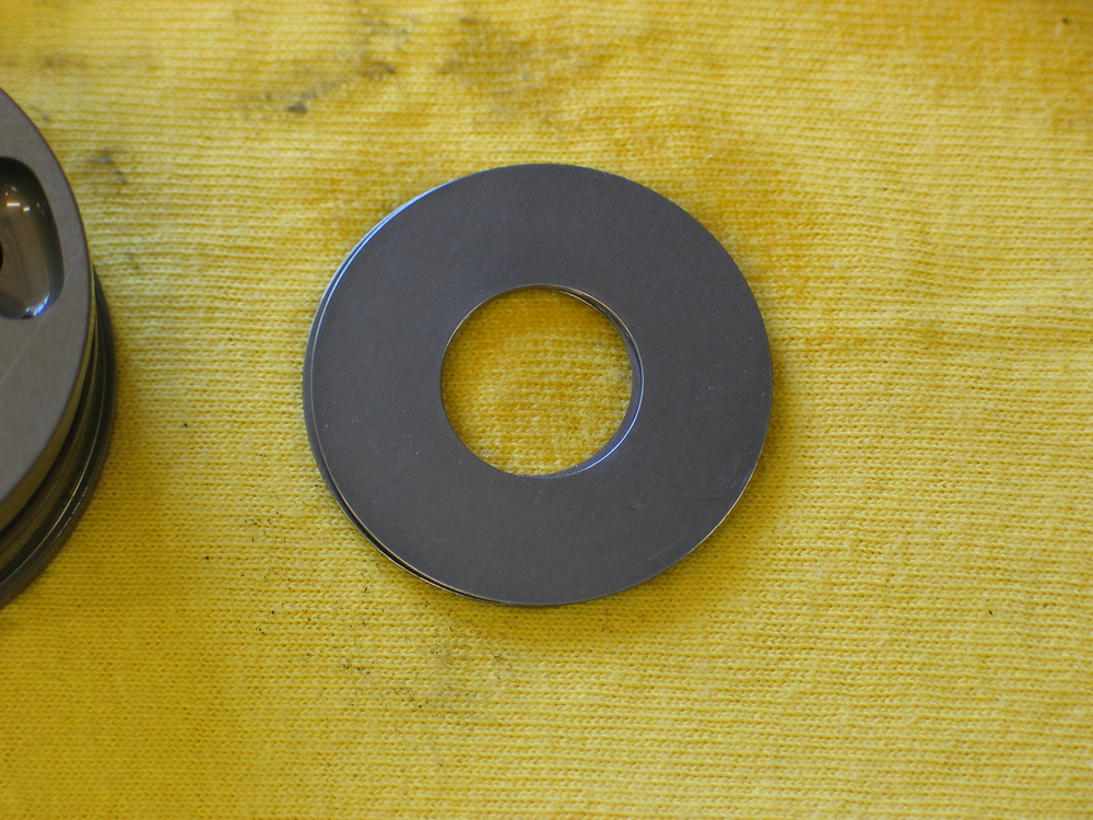
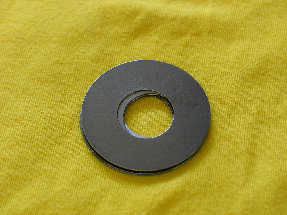
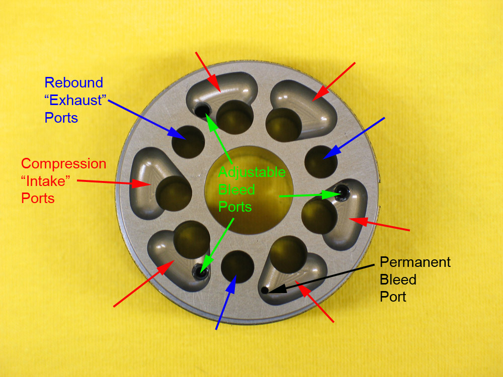
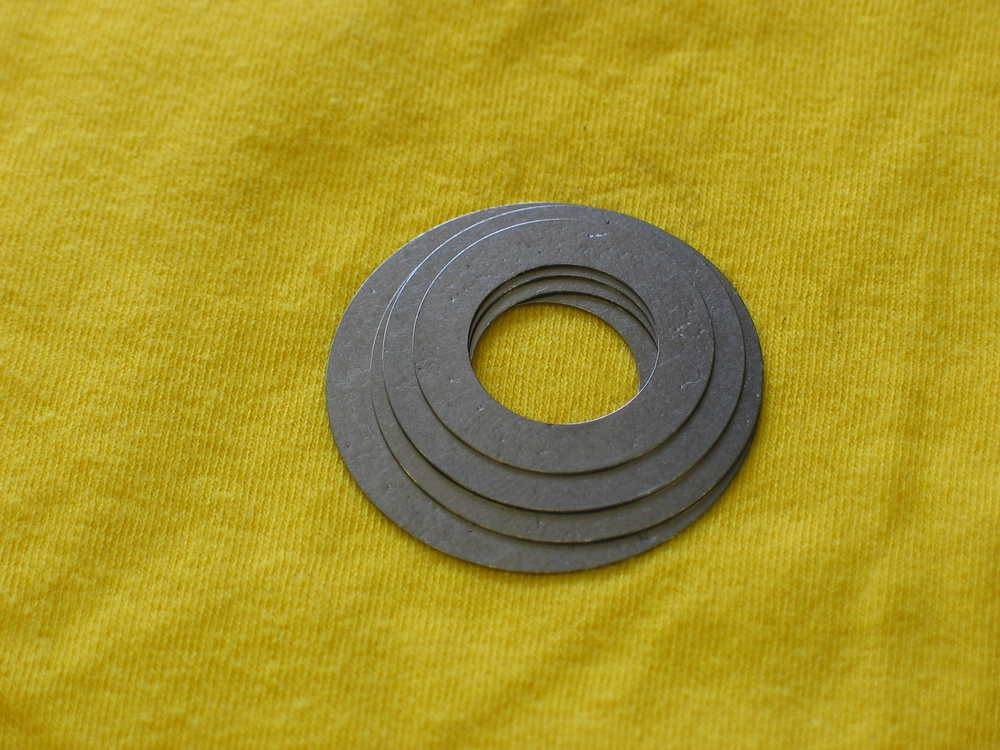
Rebound valving shim stack. The rebound valving shim stack uses a series of .012" thick shims in varying outside diameters, stacked in a pyramid fashion with the largest diameter shim next to the face of the piston, and successively smaller diameter shims stacked after that. |
||||||||||||||||||||||||||||||||||||||||||||
 |
Rebound valving shim stack. There are a maximum of six possible shim diameters, referenced as 1 through 6, with 6 being the largest diameter. Larger diameter shims provide more damping than smaller diameter shims. In the "stock" configuration, the rebound stack uses all six shims, stacked in order of decreasing diameter starting at the piston face and working out. That is, the stock rebound stack, starting at the piston, is: 6,5,4,3,2,1. This pic illustrates just four of the six shims in use. |
||||||||||||||||||||||||||||||||||||||||||||
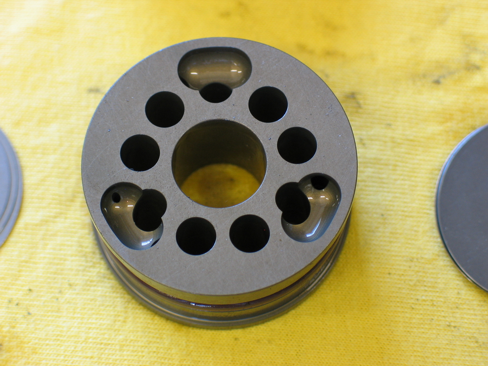 |
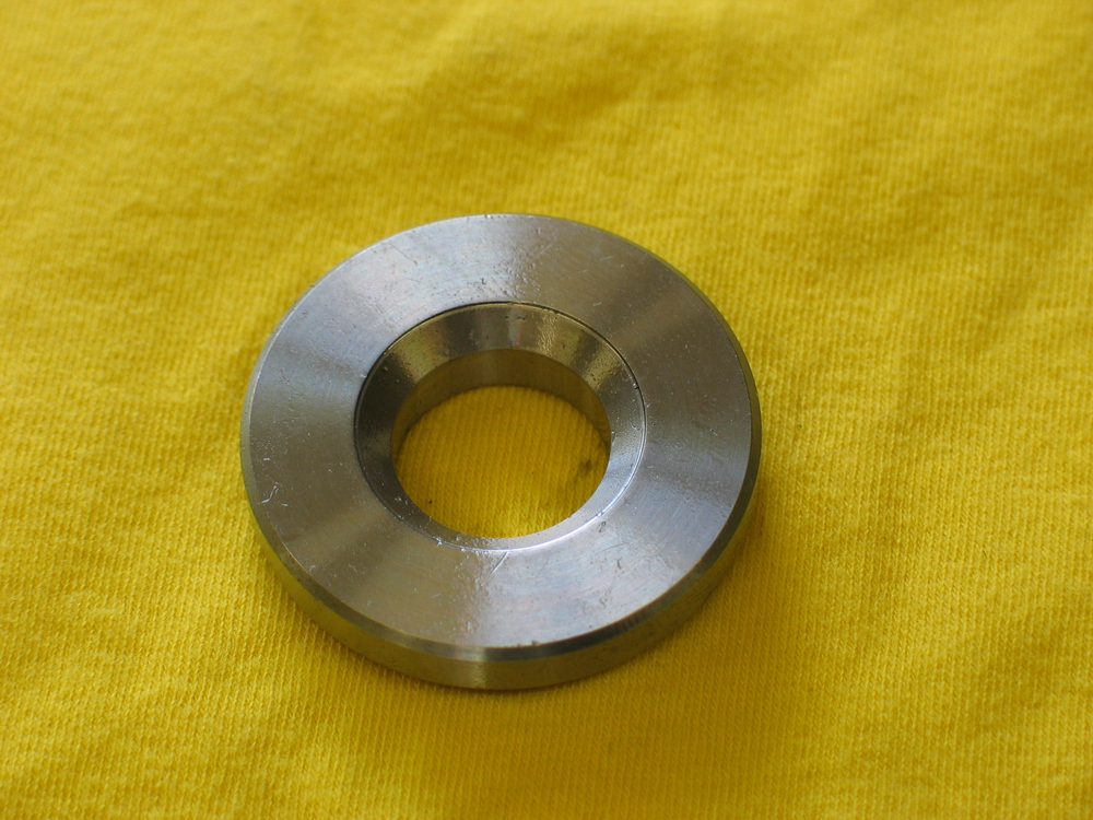
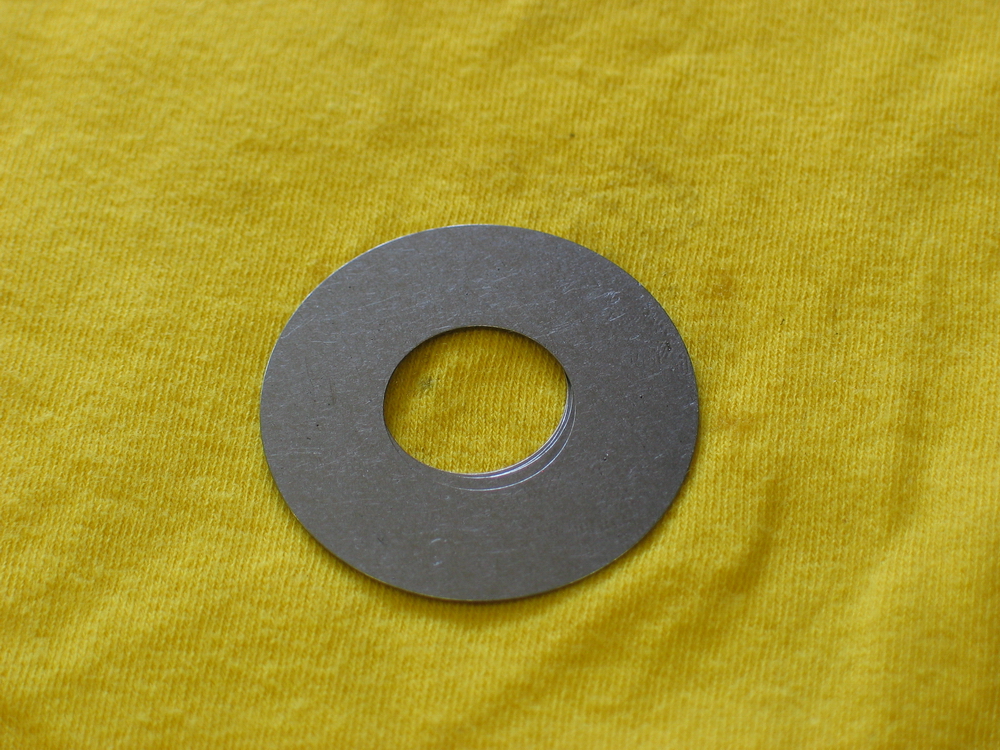
Rebound side of the piston. | ||||||||||||||||||||||||||||||||||||||||||||
 |
Compression side of the piston. | ||||||||||||||||||||||||||||||||||||||||||||
 |
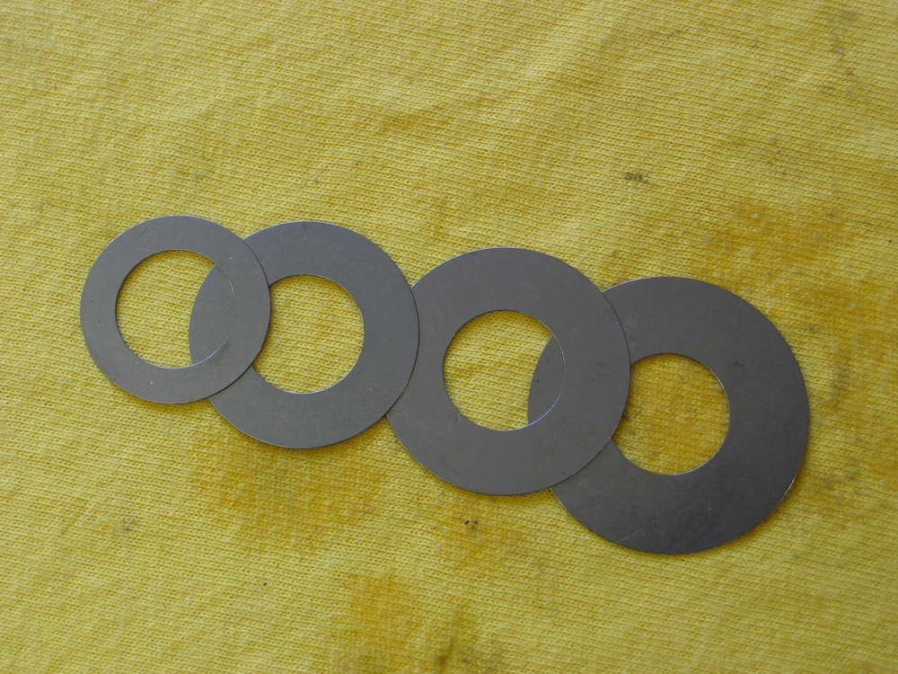
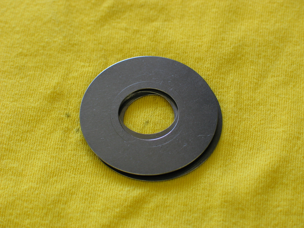
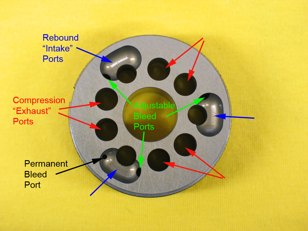
Compression valving shim stack. The compression valving shim stack uses a series of .015" thick shims in varying outside diameters, stacked in a pyramid fashion with the largest diameter shim next to the face of the piston, and successively smaller diameter shims stacked after that, but with two additional large shims stacked on top of the smallest. |
||||||||||||||||||||||||||||||||||||||||||||
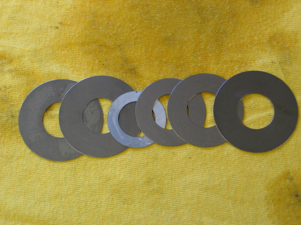 |
Compression valving shim stack. The compression shims are also referenced as 1 through 6, with 6 being the largest diameter. Again, larger diameter shims provide more damping than smaller diameter shims. In the "stock" configuration, the compression stack uses eight shims, stacked in order of decreasing diameter starting at the piston face and working out, with the addition of two additional #6 shims on stop of the #1 to provide additional damping on the compression stroke of the shock.. That is, the stock compression stack, starting at the piston, is: 6,5,4,3,2,1,6,6. This pic illustrates just six of the eight shims in use. |
||||||||||||||||||||||||||||||||||||||||||||
| The "stock" configuration of the shim stacks is only a base for the customer. The shims can be stacked differently based on the users preference. Additional shims are available from Ballistic Fabrication. | |||||||||||||||||||||||||||||||||||||||||||||
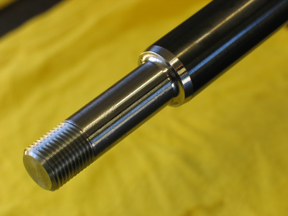 |
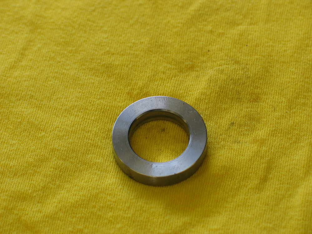
The bare machined end of the piston end of the shock shaft. Quality of machining throughout the shocks is clearly evident here. |
||||||||||||||||||||||||||||||||||||||||||||
Reassembly / Bleeding |
|||||||||||||||||||||||||||||||||||||||||||||
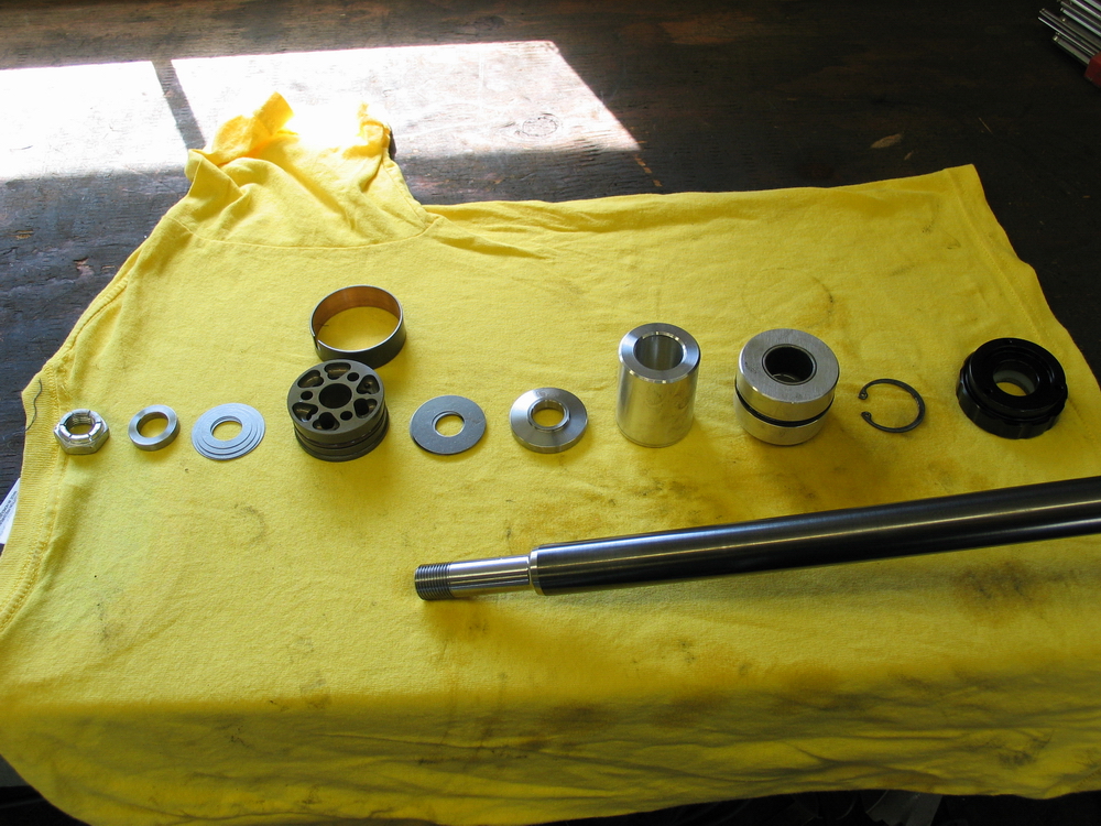 |
Parts of the shock shaft laid out, right to left, from rod-end to piston end. That is, the rightmost parts in the picture are those towards the rod-end end on the shock shaft. Those parts on the left side are the parts closest to the piston-end of the shock shaft. Individual rebuild parts are available direct from Ballistic Fabrication, should you need to replace or refresh any seals or need to replace a worn or broken component. |
||||||||||||||||||||||||||||||||||||||||||||
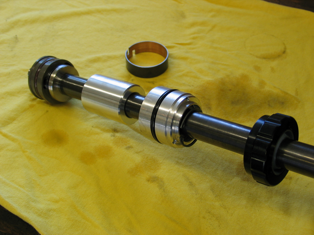 |
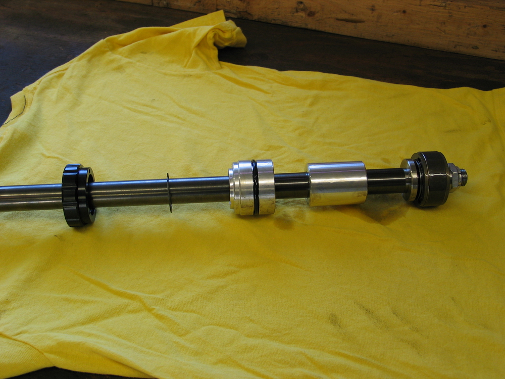
As above, assembled on the shaft. If you study the picture above and then this one, you should be able to see how my system for keeping the correct order and orientation of parts works. In the above picture, starting from right to left, each piece would be picked up and the side that was facing down, touching the yellow T-shirt would be positioned facing the shaft and then the part slid on the shaft. The result would be the picture at left. |
||||||||||||||||||||||||||||||||||||||||||||
The following shows pics of both sides of each part on the shock shaft. In the left column - the rod-end side of the part (i.e. the side that faces the rod-end on the end of the shock shaft, in other words, the side you slide on the shaft when assembling the shock). In the right column the pics illustrate the piston-end side of the part (i.e. the side facing the piston or inner-most end of the shaft). The pics are shown in order, from the rod-end to the piston end - in other words in the order you would place them on the shaft when assembling the shock.
Once the shaft and piston are reassembled and the locknut tightened, proceed to reassemble and bleed the shock as follows:
|
|||||||||||||||||||||||||||||||||||||||||||||
|
|||||||||||||||||||||||||||||||||||||||||||||
 |
Sources: Ballistic Fabrication 2010 W. McMillan St |
|