 |
Basic Hydraulics By Bill "BillaVista" Ansell |
IntroductionWhat exactly is cavitation, and why should I care? What are the functions of the fluid reservoir? Should I use pipe, tubing, or hose to connect my components? If you have ever pondered the answer to these questions, and many many more, then this is the section for you. It will be a bit dry, lots of theory and definitions, and not many pictures. However, I felt it was vital to include it, so that, for instance - when we later discuss hydraulic steering and talk about concepts like flow and pressure drop and such, we know we have a good basic understanding of the fundamentals. |
 |
I know many of you will not read it all, or even much of it. That's fine and expected, but don't complain to me later when I explain the use of some component on your 4x4 steering system by quoting Pascal's law and you're lost :-) If nothing else - this section can exist as a knowledge base, so that later, should we need to debate some topic (should my system be sealed or vented? do I need a pressure relief valve? etc.) we will at least have some credible facts at our fingertips to back up our positions. The information in this section is drawn primarily from 3 main sources. They are: (click name to view the document in .pdf format)
Much of the basics is also available in many basic hydraulics manuals and physics text books . I claim no credit for this material - I am merely presenting aspects of it that I feel are relevant to our needs and discussion. I have no ethical problems with this whatsoever because
I have bothered to extract, edit, and add comments to this open source information because I feel it IS important that we share common understanding of facts, and use some semblance of standard terminology in our exploration of hydraulics and particularly hydraulic steering. I have not simply sent you to the references (though they are available and I do recommend you read them) because they are large and very general in nature (the Army manual is 174 pages long), as one would expect; the documents having been themselves written by very LARGE entities with broad interests. So I felt that I could do a service to my readers by extracting only that data that I feel is useful and relevant (the study of hydraulics would, after all, fill several large books) and, in a sweeping delusion of grandeur I actually peppered the irrefutable factual text from the acknowledged experts with my own little comments - purportedly to add emphasis and explanation that some might find illuminating or useful. I guess you'll have to decide if I was right or not! As a final note, keep in mind that much of the basic facts of hydraulics can be applied to many more vehicular systems than just "full hydraulic steering" for a hardcore 4x4. Normal power steering, all vehicular service brakes, and automatic transmissions are three of the more common applications of hydraulics of interest to the automotive enthusiast. So you just may gain a better understanding of these as we go along ......think of it as a nice bonus! I have highlighted what I believe to be the most critical information in bold text. My comments are identified by being in italics. This part, Basic Hydraulics, is broken up into sections that roughly follow the components that make up any basic hydraulic system. Specifically:
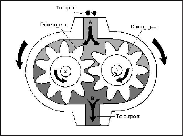
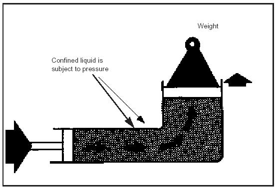
1. Basic Hydraulic Physics Hydraulics is the science of transmitting force and/or motion through the medium of a confined liquid. In a hydraulic device, power is transmitted by pushing on a confined liquid. |
|
 |
Basic hydraulic device | ||||||||||||||||||||||||||||||||||||||||||||||||||||||||||||||||||||||||||||||||||||||||||||
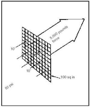
1-1. Pressure and Force. Pressure is force exerted against a specific area (force per unit area) expressed in pounds per square inch (psi). A fluid is any liquid or gas (vapour). Force is anything that tends to produce or modify (push or pull) motion and is expressed in pounds. Pressure can be created by squeezing or pushing on a confined fluid only if there is a resistance to flow. The two ways to push on a fluid are by the action of a mechanical pump or by the weight of the fluid. Force. The relationship of force,
pressure, and area is as follows: F = PA |
|||||||||||||||||||||||||||||||||||||||||||||||||||||||||||||||||||||||||||||||||||||||||||||
 |
The relationship between Pressure, Area, and Force. | ||||||||||||||||||||||||||||||||||||||||||||||||||||||||||||||||||||||||||||||||||||||||||||
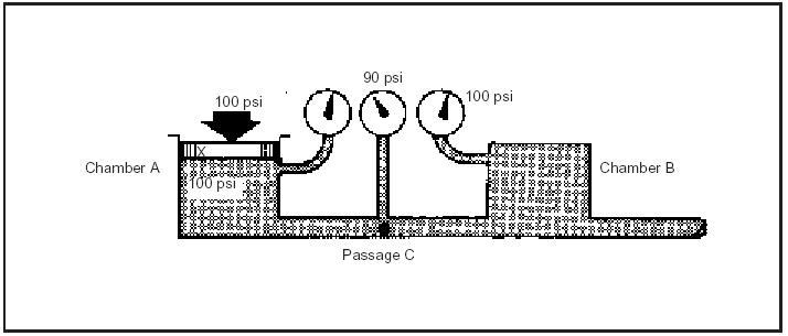
1-2. Pascal's Law. Pressure in a confined fluid is transmitted undiminished in every direction and acts with equal force on equal areas and at right angles to a container's walls. |
|||||||||||||||||||||||||||||||||||||||||||||||||||||||||||||||||||||||||||||||||||||||||||||
 |
Pascal's Apparatus. | ||||||||||||||||||||||||||||||||||||||||||||||||||||||||||||||||||||||||||||||||||||||||||||
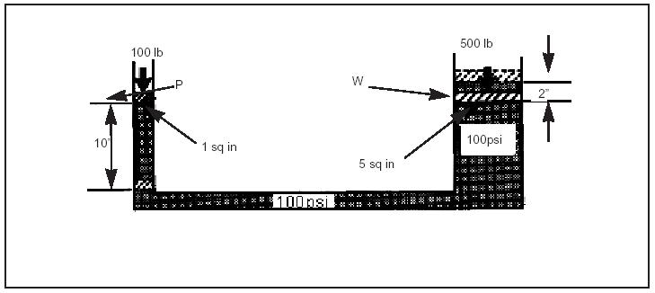
The above picture shows the apparatus
that Pascal used to develop his law. It consisted of two connected cylinders
of different diameters with a liquid trapped between them. Pascal found that
the weight of a small piston will balance the weight of a larger piston as long
as the piston’s areas are in proportion to the weights. In the small cylinder,
a force of 100 pounds on a 1-squareinch piston creates a pressure of 100 psi.
According to Pascal's Law, this pressure is transmitted undiminished in every
direction. In the larger cylinder, the 100 psi of pressure from the small cylinder
is transmitted to an area of 5 square inches, which results in a force of 500
pounds on the second piston. The force has been multiplied 5 times—a mechanical
advantage of 5 to 1. Using the same factors, you can determine the distance
the pistons move. For example, if the small piston moves down 10 inches, the
larger piston will move up 2 inches. Use the following to determine the distance: D2= F1 x D1 / F2 where— If you think about these basics, they explain the extreme utility of hydraulics. They explain why it is possible to lift massive weights using a hydraulic jack with very little input force required. They also explain the basics of automotive hydraulic service breaks, where one piston (the small piston) is the master cylinder piston, and one piston (the large [piston) is the disc break calliper piston. These basic laws also explain why statements like "using larger diameter brake lines (or any hydraulic line) will cause the brakes (or any hydraulic device) to operate more quickly" are completely false. Remember, once the brake system is full of fluid and bled of air, think of the hydraulic fluid as just a very flexible mechanical connection. It doesn't compress, it doesn't "travel" along the lines - it transmits pressure "undiminished in every direction and acts with equal force on equal areas (including the brake calliper pistons) and at right angles to a container's walls." 1-3. Flow. Flow is the movement of a hydraulic fluid caused by a difference in the pressure at two points. In a hydraulic system, flow is usually produced by the action of a hydraulic pump—a device used to continuously push on a hydraulic fluid. The two ways of measuring flow are velocity and flow rate. a. Velocity. b. Flow Rate. 1-4. Energy, Work, and Power. Energy is the ability to do work and is expressed in foot-pounds (ft/lbs). Three forms of energy most important in hydraulics are potential, kinetic, and heat. Work measures accomplishments; it requires motion to make a force do work. Power is the rate of doing work or the rate of energy transfer Recall that energy can never be created or destroyed, merely converted from one form to another. Power then, is the rate at which energy is converted from one form to another. For example, your engine's power is a measure of the rate at which it can convert chemical energy in the gasoline to kinetic energy (truck motion) and heat and noise. a. Potential Energy. b. Kinetic Energy. c. Heat Energy and Friction.
|
|||||||||||||||||||||||||||||||||||||||||||||||||||||||||||||||||||||||||||||||||||||||||||||
 |
Bernoulli's Principle. | ||||||||||||||||||||||||||||||||||||||||||||||||||||||||||||||||||||||||||||||||||||||||||||
d. Relationship Between Velocity
and Pressure. e. Work. To do work in a hydraulic system, flow must be present. Work, therefore, exerts a force over a definite distance. It is a measure of force multiplied by distance. f. Power. The standard unit of power
is horsepower (hp). One hp is equal to 550 ft/lbs of work every second. Use the
following equation to find power: 2. Hydraulic Systems 2-1. Hydraulic System Components Most hydraulic systems (also called circuits, just like in electronics) contain the same basic components. Obviously, there are some systems that are very simple, and may only have the barest essential components (like a hydraulic floor jack), and others can be enormously complicated, containing hundreds of complicated components. Regardless of the design, all hydraulic systems contain:
Most systems also have:
And some systems have:
The majority of the remainder of this article will be devoted to exploring each of these in a little more detail. A hydraulic system contains and confines a liquid in such a way that it uses the laws governing liquids, explained above, to transmit power and do work. 2-2. Basic Hydraulic Systems. The advantages of hydraulic systems over other methods of power transmission are:
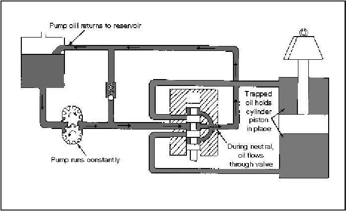
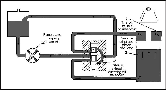
The main disadvantage of a hydraulic system is maintaining the precision parts when they are exposed to bad climates and dirty atmospheres. Protection against rust, corrosion, dirt, oil deterioration, and other adverse environment is very important. This is especially critical in the harsh, dirty, mobile, stressful, vibration filled environment in which we operate hydraulic systems on our 4x4s Most hydraulic systems that are more complicated than your basic floor-jack are grouped into two broad categories. This is certainly true of hydraulic steering systems. The two categories are defined based on how a main fluid control valve functions when the system is working and not-working. The valve function is dependant on the type of pump in use (more on pumps and valves later). Suffice to say, at this stage, that some pumps continuously pump, providing fluid pressure and flow constantly. When a system with this type of pump is not working (i.e. when the fluid is not directed to the actuators) the fluid must be able to pass through the valve and back to the reservoir. The valve is "open" in the center to allow this, hence these systems are known as "open center" design. In contrast, some pumps only create flow and pressure when required (on demand) and as such, their main control valves do not need to allow the fluid back into the reservoir, and so are closed in the center. Not surprisingly, these are called closed-center systems. |
|||||||||||||||||||||||||||||||||||||||||||||||||||||||||||||||||||||||||||||||||||||||||||||
 |
Open-Center System. | ||||||||||||||||||||||||||||||||||||||||||||||||||||||||||||||||||||||||||||||||||||||||||||
| Open-Center System. In this system, a control-valve spool must be open in the center to allow pump flow to pass through the valve and return to the reservoir. To operate several functions simultaneously, an open-center system must have the correct connections, which are discussed below. An open-center system is efficient on single functions but is limited with multiple functions. This system is satisfactory as long as only one valve is operating at a time. When this happens, the full output of the pump at full system pressure is available to that function. However, if more than one valve is operating, the total of the pressures required for each function cannot exceed the system’s relief setting. | |||||||||||||||||||||||||||||||||||||||||||||||||||||||||||||||||||||||||||||||||||||||||||||
 |
Closed-Center System. | ||||||||||||||||||||||||||||||||||||||||||||||||||||||||||||||||||||||||||||||||||||||||||||
Closed-Center System. In this system, a pump can rest when the oil is not required to operate a function. This means that a control valve is closed in the center, stopping the flow of the oil from the pump. 2-3. Rules for working with hydraulics Three most important rules to be followed when working with hydraulics are:
Rule 1 Concerns cleanliness during the installation of the hydraulic system. Hoses, pipes and fittings are never clean after being worked on and must therefore always be cleaned immediately prior to installation. Pipes, including pipe bends, should preferably be cleaned with a plug of crepe paper or lint-free cloth soaked in paraffin and blown through the pipe with compressed air. This process must be repeated with several plugs until a completely clean plug emerges. The blanking plugs fitted in all pumps, motors, valves, etc. must not be re-moved until just before the components are installed. Workshops, work stations, tools and clothing must also be as clean as possible. Rule 2 Concerns cleanliness during daily operation of a hydraulic system. The tools used for filling must of course be perfectly clean and the oil filled into the system must be filtered through filters of the same fineness as the finest in the system, normally 5 µm, but in any event no coarser than 10 µm nominal. Rule 3 Concerns cleanliness during inspection and repair. Before a hydraulic component is removed, both the component itself and the immediate surroundings must be clean. All open parts, pipes, hoses, etc. must be blanked off with, for example, plastic bags bound on so that dirt and dust cannot enter the system when it is in standstill. The other critical concern with hydraulic systems is fluid temperature. Most suppliers prescribe 194 °F (90°C) as an absolute maximum. We shall examine why, and what to do about it in the section on fluid. 2-4. System Design Each component in the system must be compatible with and form an integral part of the system. For example, an inadequate size filter on the inlet of a pump can cause cavitation and subsequent damage to the pump. Each component in the system has a maximum rated speed, torque or pressure. Loading the system beyond the specifications simply increases the possibility of failure All lines must be of proper size and free of restrictive bends. An undersized or restricted line results in a pressure drop in the line itself. Some components must be mounted in a specific position with respect to other components or the lines. The housing of an in-line pump, for example, must remain filled with fluid to provide lubrication. Systems should be designed for a correct operating pressures. The correct operating pressure is the lowest pressure which will allow adequate performance of the system function and still remain below the maximum rating of the components and machine. Always set and check pressures with a gauge Knowing the System is probably the greatest aid to troubleshooting problems later on. 3. Reservoirs 3-1. Reservoirs. A reservoir stores a liquid that is not being used in a hydraulic system. It has many other important functions too:
a. Construction. A properly constructed reservoir should be able to dissipate heat from the oil, separate air from the oil, and settle out contaminates that are in it. Reservoirs range in construction from small steel stampings to large cast or fabricated units. The large tanks should be sandblasted after all the welding is completed and then flushed and steam cleaned. b. Shape. Design features of a reservoir. It should be high and narrow rather than shallow and broad. The oil level should be as high as possible above the opening to a pump's suction line. This prevents the vacuum at the line opening from causing a vortex or whirlpool effect, which would mean that a system is probably taking in air. Aerated oil will not properly transmit power because air is compressible. Aerated oil has a tendency to break down and lose its lubricating ability. To increase the ability of the tank to separate dirt and water, the bottom must be slightly inclined (deepest end opposite the inlet/outlet end). An ordinary cock (without handle) is fitted so that impurities can easily be drained off. Increased separation of the air that is always present in the oil can be obtained by fitting an inclined coarse metal strainer (approx. 25-50 mesh/ inch) by the return line. Both suction and return pipes must be cut diagonally. The ends of the pipes must be located 2-4 times the pipe diameter above the bottom of the tank, partly to avoid foaming at the return line, and partly to prevent air from being drawn into the suction line, especially when the vehicle/vessel heels over to one side. c. Size. A reservoir must be large enough so that it has a reserve of oil with all the cylinders in a system fully extended. An oil reserve must be high enough to prevent a vortex at the suction line's opening. A reservoir must have sufficient space to hold all the oil when the cylinders are retracted, as well as allow space for expansion when the oil is hot. A common-size reservoir on a mobile machine is a 20- or 30-gallon tank used with a 100- GPM system. Many 10-GPM systems operate with 2- or 3-gallon tanks because these mobile systems operate intermittently, not constantly. For stationary machinery, a rule of thumb is that a reservoir’s size should be two to three times a pump’s output per minute. A large size tank is highly desirable for cooling. The large surface areas exposed to the outside air transfer heat from the oil. Also, a large tank helps settle out the contaminates and separates the air by reducing recirculation. If the application is mobile, if there is no cooler built into the system, and provided the tank is located where air circulation is good, ideally the size of the tank should be approx. 2-3 times the capacity of the pump per minute. In our 4x4 systems we are unlikely to be able to achieve such large reservoir capacities as this, but the important lesson is that your reservoirs cannot be too big - it is best to use the largest possible reservoir space and weight restrictions allow. d. Location. Most mobile equipment reservoirs are located above the pumps. This creates a flooded-pump-inlet condition. This condition reduces the possibility of pump cavitation—a condition where all the available space is not filled and often metal parts will erode. Flooding the inlet also reduces the vortex tendency at a suction pipe's opening. The location of a reservoir affects heat dissipation. Ideally, all tank walls should be exposed to the outside air. Heat moves from a hot substance to a cold substance; heat transfer is greatest when there is a large temperature difference. e. Ventilation and Pressurization. Most reservoirs are vented to the atmosphere. A vent opening allows air to leave or enter the space above the oil as the level of the oil goes up or down. This maintains a constant atmospheric pressure above the oil. A reservoir filter cap, with a filter element, is often used as a vent. Some reservoirs are pressurized, using a simple pressure-control valve rather than a vented one. A pressure-control valve automatically lets filtered air into a tank but prevents air release unless the pressure reaches a preset level. A pressurized reservoir takes place when the oil and air in a tank expand from heat. f. Line Connections. A pump suction and a tank's return lines should be attached by flanges or by welded heavy-duty couplings. Standard couplings usually are not suitable because they spread when welded. If a suction line is connected at the bottom, a coupling should extend well above the bottom, inside the tank; residual dirt will not get in a suction line when a tank or strainer is cleaned. A return line should discharge near a tank's bottom always below the oil level. A pipe is usually cut at a 45-degree angle and the flow aimed away from a suction line to improve circulation and cooling. A baffle plate is used to separate a suction line from a return line. This causes the return oil to circulate around an outer wall for cooling before it gets to the pump again. A baffle plate should be about two-thirds the height of a tank. The lower corners are cut diagonally to allow circulation. They must be larger in area than a suction line's cross section. Otherwise the oil level between a return and a suction side might be uneven. Baffling also prevents oil from sloshing around when a machine is moving. Many large reservoirs are cross-baffled to provide cooling and prevent sloshing. g. Maintenance. Maintenance procedures include draining and cleaning a reservoir. A tank should have a dished bottom that is fitted with a drain plug at its lowest point; a plug fitting should be flushed with the inside of a tank to allow for full drainage. A reservoir should have a sight gauge or dipstick for checking the oil level to prevent damage from lubrication loss. An element in a filter in a return line will require regular changing. When a reservoir is pressurized by compressed air, moisture can become a maintenance problem. A tank should have a water trap for moisture removal 4. Strainers and Filters 4-1. Strainers and Filters. To keep hydraulic components performing correctly, the hydraulic liquid must be kept as clean as possible. Foreign matter and tiny metal particles from normal wear of valves, pumps, and other components are going to enter a system. Strainers, filters, and magnetic plugs are used to remove foreign particles from a hydraulic liquid and are effective as safeguards against contamination. a. Strainers. A strainer is the primary filtering system that removes large particles of foreign matter from a hydraulic liquid. Even though its screening action is not as good as a filter's, a strainer offer less resistance to flow. b. Filters. A filter removes small foreign particles from a hydraulic fluid and is most effective as a safeguard against contaminates. They are classified as full flow or proportional flow. (1) Full-Flow Filter . In a full-flow filter, all the fluid entering a unit passes through a filtering element. Although a full-flow type provides a more positive filtering action, it offers greater resistance to flow, particularly when it becomes dirty. (2) Proportional-Flow Filters This filter operates on the venturi principle in which a tube has a narrowing throat (venturi) to increase the velocity of fluid flowing through it. Flow through a venturi throat causes a pressure drop at the narrowest point. This pressure decrease causes a sucking action that draws a portion of a liquid down around a cartridge through a filter element and up into a venturi throat. 4-2. Filtering Material and Elements. The general classes of filter materials are mechanical, absorbent inactive, and absorbent active. Mechanical filters contain closely woven metal screens or discs. They generally remove only fairly coarse particles. Absorbent inactive filters, such as cotton, wood pulp, yarn, cloth, or resin, remove much smaller particles; some remove water and water-soluble contaminants. The elements often are treated to make them sticky to attract the contaminants found in hydraulic oil. Absorbent active materials, such as charcoal and Fuller's Earth (a clay like material of very fine particles used in the purification of mineral or vegetable-base oils), are not recommended for hydraulic systems. The three basic types of filter elements are surface, edge, and depth. A surface-type element is made of
closely woven fabric or treated paper. Oil flows through the pores of the filter
material, and the contaminants are stopped. 4-3. Filter selection The degree of filtering and filter size are based on many different criteria, so that generalization is seldom possible. The most important factors to be considered are as follows:
If you answer these questions about a 4x4 hydraulic steering system, you can see that high quality filtration of your full hydraulic steering system is an absolute must. 5. Plumbing / Lines 5-1. Types of Circulatory Systems. Pipes and fittings, with their necessary seals, make up a circulatory system of liquid-powered equipment. Properly selecting and installing these components are very important. If improperly selected or installed, the result would be serious power loss or harmful liquid contamination. The following is a list of some of the basic requirements of a circulatory system:
The three common types of lines in liquid-powered systems are pipes, tubing, and flexible hose, which are also referred to as rigid, semi rigid, and flexible line. a. Tubing. The two types of tubing used for hydraulic lines are seamless and electric welded. Both are suitable for hydraulic systems. Seamless tubing is made in larger sizes than tubing that is electric welded. Seamless tubing is flared and fitted with threaded compression fittings. Tubing bends easily, so fewer pieces and fittings are required. Unlike pipe, tubing can be cut and flared and fitted in the field. Generally, tubing makes a neater, less costly, lower-maintenance system with fewer flow restrictions and less chances of leakage. Knowing the flow, type of fluid, fluid velocity, and system pressure will help determine the type of tubing to use. (Nominal dimensions of tubing are given as fractions in inches or as dash numbers. A dash number represents a tube’s outside diameter [OD] in sixteenths of an inch.) A system’s pressure determines the thickness of the various tubing walls. Tubing is commonly used in automotive braking systems. b. Piping. You can use piping that is threaded with screwed fittings with diameters up to 1 1/4 inches and pressures of up to 1,000 psi. Where pressures will exceed 1,000 psi and required diameters are over 1 1/4 inches, piping with welded, flanged connections and socket-welded size are specified by nominal inside diameter (ID) dimensions. The thread remains the same for any given pipe size regardless of wall thickness. Piping is used economically in larger-sized hydraulic systems where large flow is carried. It is particularly suited for long, permanent straight lines. Piping is taper-threaded on its OD into a tapped hole or fitting. However, it cannot be bent. Instead, fittings are used wherever a joint is required. This results in additional costs and an increased chance of leakage. Piping is of no use to us as hydraulic line in our 4x4s. c. Flexible Hosing. When flexibility is necessary in liquid-powered systems, use hose. Examples would be connections to units that move while in operation to units that are attached to a hinged portion of the equipment or are in locations that are subjected to severe vibration. Flexible hose is usually used to connect a pump to a system. The vibration that is set up by an operating pump would ultimately cause rigid tubing to fail. A 4x4 Hydraulic Steering System will most likely be exclusively plumbed with flexible hose. When installing flexible hose, do not twist it. Doing so reduces its lift and may cause its fittings to loosen. An identification stripe that runs along the hose length should not spiral, which would indicate twisting. Protect flexible hose from chafing by wrapping it lightly with tape, when necessary. The minimum bend radius for flexible hose varies according to its size and construction and the pressure under which a system will operate. Consult the applicable publications that contain the tables and graphs which show the minimum bend radii for the different types of installations. Bends that are too sharp will reduce the bursting pressure of flexible hose considerably below its rated value. Install flexible hose so that it will be subjected to a minimum of flexing during operation. Never stretch hose tightly between two fittings. When under pressure, flexible hose contracts in length and expands in diameter. Keep the lines as short and free of bends as possible. Install all the lines so you can remove them without dismantling a circuit’s components or without bending or springing them to a bad angle. Add supports to the lines at frequent intervals to minimize vibration or movement; never weld the lines to the supports. Since flexible hose has a tendency to shorten when subjected to pressure, allow enough slack to compensate for this problem. 5-2. Sizing hydraulic lines. The size of tubing or flexible hose required in a given hydraulic system depends on:
Pressure drop must be as small as possible. Remember that when the internal diameter is doubled, the flow area of the pipe is quadrupled. In order to calculate the exact size required for your lines, you need a nomogram like this: |
|||||||||||||||||||||||||||||||||||||||||||||||||||||||||||||||||||||||||||||||||||||||||||||
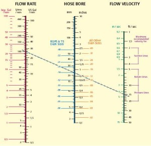 |
Hydraulic line size selection nomogram. Click on pic to access full nomogram in .pdf format, perfect for printing and using, complete with instructions and examples. |
||||||||||||||||||||||||||||||||||||||||||||||||||||||||||||||||||||||||||||||||||||||||||||
Use of the nomogram to determine line size requires knowledge of 2 variables - the flow rate of the system (likely determined by the pump's rated capacity - for example 5 gpm) in gallons per minute. With that knowledge, one then only needs to know whether the line is to be used as suction line, pressure line or return line. This is because the second variable required to use the nomogram is flow velocity, which is based on whether the line is suction, return, or pressure. The recommended flow velocity for the different line uses are as follows (also represented by dashed regions on the nomogram):
Once the flow rate in gpm and flow velocity in ft/sec are known, simply draw a straight line between the 2 values and where it crosses the middle diagram, read off the required line size. 5-3. Tubing Do’s And Don’ts.
*** The following EXCELLENT information on hydraulic hoses are pdf files from Ryco Hydraulics. They are excellent, and should be read by all **** 5-4. Hose Selection and Maintenance 5-5. Safety guide for selection and use of Hose and fittings 5-6. Hose Assembly and Installation Guide 5-7. Circulatory Systems maximum temperature and working pressures 6. Fittings and Connectors 6-1. Fittings and Connectors. Many different types of connectors are available for fluid-powered systems. The type that you will use will depend on the type of circulatory system (pipe, tubing, or flexible hose), the fluid medium, and the maximum operating pressure of a system. Some of the most common types of connectors are described below: a. Threaded Connectors. Threaded connectors are used in some low-pressure liquid powered systems. They are usually made of steel, copper, or brass, in a variety of designs. Standard pipe threads are tapered slightly to ensure tight connections. To prevent seizing (threads sticking), apply a pipe-thread compound to the threads. Keep the two end threads free of the compound so that it will not contaminate the fluid. Pipe compound, when improperly applied, may get inside the lines and harm the pumps and the control equipment. b. Flared Connectors. The common connectors used in circulatory systems consist of tube lines. These connectors provide safe, strong, dependable connections without having to thread, weld, or solder the tubing. The most common example being the standard automotive double-flared hydraulic brake lines. A connector consists of a fitting, a sleeve, and a nut. Tubing used with flared connectors must be flared before being assembled. A nut fits over a sleeve and, when tightened, draws the sleeve and tubing flare tightly against a male fitting to form a seal. A male fitting has a cone-shaped surface with the same angle as the inside of a flare. A sleeve supports the tube so that vibration does not concentrate at the edge of a flare but that it does distribute the shearing action over a wider area for added strength. Tighten the tubing nuts with a torque wrench to the value specified in applicable regulations. If an aluminium alloy flared connector leaks after tightening to the specified torque, do not tighten it further. Disassemble the leaking connector and correct the fault. If a steel connector leaks, you may tighten it 1/6 turn beyond the specified torque in an attempt to stop the leak. c. Hose couplings. Hose Couplings can be broadly divided into two types:
|
|||||||||||||||||||||||||||||||||||||||||||||||||||||||||||||||||||||||||||||||||||||||||||||
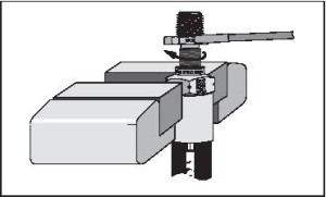 |
A field attachable fitting that can be assembled onto the hose with only a vise and hand tools. | ||||||||||||||||||||||||||||||||||||||||||||||||||||||||||||||||||||||||||||||||||||||||||||
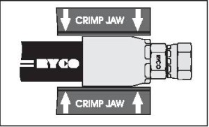 |
A crimp-on fitting that requires a special crimping machine to assemble t onto the hydraulic hose. | ||||||||||||||||||||||||||||||||||||||||||||||||||||||||||||||||||||||||||||||||||||||||||||
6-2. Coupling / Fitting data The following pdf files from Ryco Hydraulics. include all you would ever need to know about various hydraulic couplings (fittings)
7. Fluid 7-1. Fluid basics The oil in a hydraulic system must first and foremost transfer energy, but the moving parts in components must also be lubricated to reduce friction and consequent heat generation. Additionally, the oil must lead dirt particles and friction heat away from the system and protect against corrosion. Oil requirements include:
Motor oils and most transmission oils contain self-cleaning additives. These are a disadvantage in hydraulic systems. For example, water condensed from the oil cannot be drained off; it forms an emulsion with the oil. This in turn leads to filters becoming clogged too quickly. There is evidence that more than 70% of all problems with hydraulic systems can be traced directly to the condition of the oil. Normally an oil operating temperature of 86°F- 140°F (30-60°C) ought to be aimed at since the life of hydraulic oil is strongly dependent on its operating temperature. The rule-of thumb is that the useful life of an oil is halved for every 4.4°F (8°C) the temperature rises above 140°F (60°C). That is to say, at 194°F (90°C) the life of the oil is only about 10% of its life at 140°F (60°C). The reason for this is oxidation. At atmospheric pressure, all oils contain a little less than 0.03 gal (0.1 litres) of air per 0.264 gal (litre) of oil. Therefore, in practice, oxygen is always present and it reacts with the hydrocarbons making up the oil. Gradually, as oxidation increases, the oil becomes darker in colour and its' viscosity rises. Finally, the products of oxidation can no longer be dissolved in the oil, but instead settle everywhere in the system as a brown sticky layer. This will cause sticking valves and high friction in ball bearings, valve spools and pump pistons. Oxidation also produces corrosive acids. The oxidation process begins gradually, but at a certain stage the oxidation rate suddenly rises and the viscosity rises. The resulting increase in operating temperature accelerates the oxidation process even more and soon the oil becomes quite unusable as a hydraulic oil because of deposits, high viscosity and accumulated acids. It therefore pays to take care of the oil. |
|||||||||||||||||||||||||||||||||||||||||||||||||||||||||||||||||||||||||||||||||||||||||||||
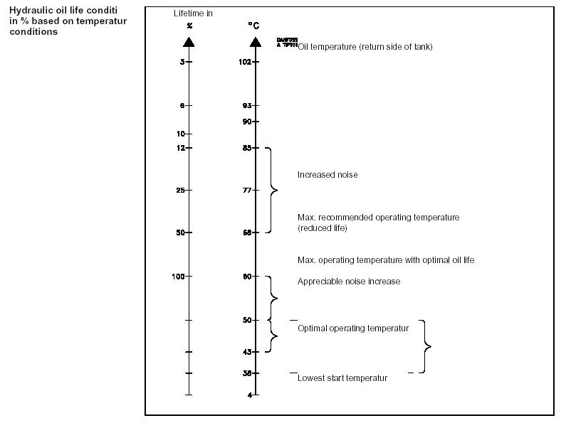 |
Hydraulic oil life conditions. | ||||||||||||||||||||||||||||||||||||||||||||||||||||||||||||||||||||||||||||||||||||||||||||
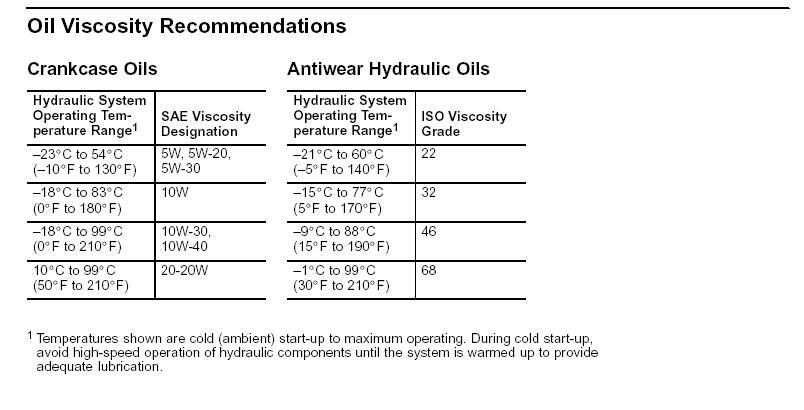 |
Oil viscosity recommendations. | ||||||||||||||||||||||||||||||||||||||||||||||||||||||||||||||||||||||||||||||||||||||||||||
7-2. Hydraulic Fluid And Temperature Recommendations For Industrial Machinery a. General Data Oil in hydraulic systems performs the dual function of lubrication and transmission of power. It constitutes a vital factor in a hydraulic system, and careful selection should be made with the assistance of a reputable supplier. Proper selection of oil assures satisfactory life and operation of the system components with particular emphasis on hydraulic pumps and motors. Generally, oil selected for use with pumps and motors are acceptable for use with valves. Critical servo valves may need special consideration. Some of the factors especially important in the selection of oil for use in an industrial hydraulic system are:
Two specific types of oil meet the requirements of modern industrial hydraulic systems:
b. Viscosity Viscosity is the measure of the fluid’s resistance to flow. Very high viscosities at start-up temperatures can cause noise and cavitational damage to pumps. Continuous operation at moderately high viscosities will tend to hold air in suspension in the oil as well as generate higher operating temperatures. This can cause noise and early failure of pumps, motors and erosion of valves. Low viscosities result in decreased system efficiency and impairment of dynamic lubrication which causes wear. c. Temperature To obtain optimum service life from both the oil and the hydraulic system, operate between 49°C (120°F) and 54°C (130°F). The maximum oil temperature normally recommended is 66°C (150°F). d. Cleanliness Thorough precautions should always be observed to ensure that the hydraulic system is clean.
e. Synthetic Fluid Type - Phosphate Ester Phosphate ester type fluids are manufactured from chemically produced esters. These types of fluids require fluorocarbon seals. Consult your fluid supplier for the types of seals which are compatible. 7-3. Hydraulic Fluid And Temperature Recommendations For Mobile Hydraulic Systems The oil in a hydraulic system serves as the power transmission medium. It is also the system’s lubricant and coolant. The selection of proper oil is a requirement for satisfactory system performance and life. Important Factors In Selecting An Oil Additives Hydraulic fluids contain a number of additive agents which materially improve various characteristics of oil for hydraulic systems. These additives are selected to reduce wear, increase chemical stability, inhibit corrosion and depress the pour point. Anti-wear Pump performance and reliability are directly affected by the anti-wear additive formulation contained in the oil. Oils providing a high level of anti-wear protection are recommended for optimum performance and long life. Viscosity Viscosity is the measure of the fluid’s resistance to flow. The oil selected must have proper viscosity to maintain an adequate lubricating film at system operating temperature. In addition to dynamic lubricating properties, oil must have sufficient body to provide an adequate sealing effect between working parts of pumps, valves, cylinders and motors, but not enough to cause pump cavitation or sluggish valve action. Optimum operating viscosity of the oil should be between 16 cSt (80 SUS) and 40 cSt (180 SUS). 8. Seals Seals are packing materials used to prevent leaks in liquid-powered systems. A seal is any gasket, packing, seal ring, or other part designed specifically for sealing. Sealing applications are usually static or dynamic, depending if the parts being sealed move in relation to one another. Sealing keeps the hydraulic oil flowing in passages to hold pressure and keep foreign materials from getting into the hydraulic passages. To prevent leakage, use a positive sealing method, which involves using actual sealing parts or materials. In most hydraulic components, you can use non-positive sealing (leakage for lubrication) by fitting the parts closely together. The strength of an oil film that the parts slide against provides an effective seal. Types of seals include: a. Static Seals. Pipe-threaded seals, seal rings used with tube fittings, valve end-cap seals, and other seals on nonmoving parts are static seals. Mounting gaskets and seals are static, as are seals used in making connections between components. A static seal or gasket is placed between parts that do not move in relation to each other. b. Dynamic Seals. In a dynamic sealing application, either a reciprocating or a rotary motion occurs between the two parts being sealed; for example, a piston-to-barrel seal in a hydraulic cylinder or a drive-shaft seal in a pump or motor. c. O-ring Seals. An O-ring is a positive seal that is used in static and dynamic applications. It has replaced the flat gasket on hydraulic equipment. When being installed, an O-ring is squeezed at the top and bottom in its groove and against the mating part. It is capable of sealing very high pressure. Pressure forces the seal against the side of its groove, and the result is a positive seal on three sides. Dynamic applications of an O-ring are usually limited to reciprocating parts that have relatively short motion. Preventing Seal Deterioration Premature deterioration of the seal can result from excessive fluid temperature. A good guide is that seal life is halved by every 20°F. rise. The cure: Incorporate sufficient heat exchangers to keep fluid temperatures below 150°F. Another factor may be compatibility of the fluid with the seal material where special fluids are used. If a doubt arises, contact your Vickers representative. The following brief review of seal materials may be helpful.
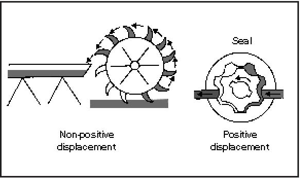
9. Pumps Hydraulic pumps convert mechanical energy from a prime mover (engine or electric motor) into hydraulic (pressure) energy. The pressure energy is used then to operate an actuator. Pumps push on a hydraulic fluid and create flow. 9-1. Pump Classifications. All pumps create flow. They operate on the displacement principle. Fluid is taken in and displaced to another point. Pumps that discharge liquid in a continuous flow are non-positive-displacement type. Pumps that discharge volumes of liquid separated by periods of no discharge are positive-displacement type. a. Non-positive-Displacement Pumps. With this pump, the volume of liquid delivered for each cycle depends on the resistance offered to flow. A pump produces a force on the liquid that is constant for each particular speed of the pump. Resistance in a discharge line produces a force in the opposite direction. When these forces are equal, a liquid is in a state of equilibrium and does not flow. If the outlet of a non-positive-displacement pump is completely closed, the discharge pressure will rise to the maximum for a pump operating at a maximum speed. A pump will churn a liquid and produce heat. Automotive power steering pumps are non-positive-displacement type pumps. b. Positive-Displacement Pumps. With this pump, a definite volume of liquid is delivered for each cycle of pump operation, regardless of resistance, as long as the capacity of the power unit driving a pump is not exceeded. If an outlet is completely closed, either the unit driving a pump will stall or something will break. Therefore, a positive-displacement-type pump requires a pressure regulator or pressure-relief valve in the system. As the fluid flows out of the other side, it is sealed against backup. This sealing is the positive part of displacement. Without it, the fluid could never overcome the resistance of the other parts in a system. c. Characteristics. The three contrasting characteristics in the operation of positive- and non-positive-displacement pumps are as follows:
|
|||||||||||||||||||||||||||||||||||||||||||||||||||||||||||||||||||||||||||||||||||||||||||||
 |
|||||||||||||||||||||||||||||||||||||||||||||||||||||||||||||||||||||||||||||||||||||||||||||
9-2. Pump Performance. Pumps are usually rated according to their volumetric output and pressure. Volumetric output (delivery rate or capacity) is the amount of liquid that a pump can deliver at its outlet port per unit of time at a given drive speed, usually expressed in GPM or cubic inches per minute. Because changes in pump drive affect volumetric output, pumps are sometimes rated according to displacement, that is the amount of liquid that they can deliver per cycle or cubic inches per revolution. Pressure is the force per unit area of a liquid, usually expressed in psi. (Most of the pressure in the hydraulic systems covered in this manual is created by resistance to flow.) Resistance is usually caused by a restriction or obstruction in a path or flow. The pressure developed in a system has an effect on the volumetric output of the pump supplying flow to a system. As pressure increases, volumetric output decreases. This drop in output is caused by an increase in internal leakage (slippage) from a pump's outlet side to its inlet side. Slippage is a measure of a pump’s efficiency and usually is expressed in percent. Some pumps have greater internal slippage than others; some pumps are rated in terms of volumetric output at a given pressure. 3-3. Displacement. Displacement is the amount of liquid transferred from a pump’s inlet to its outlet in one revolution or cycle. In a rotary pump, displacement is expressed in cubic inches per revolution and in a reciprocating pump in cubic inches per cycle. If a pump has more than one pumping chamber, its displacement is equal to the displacement of one chamber multiplied by the number of chambers. Displacement is either fixed or variable. a. Fixed-Displacement Pump. In this pump, the GPM output can be changed only by varying the drive speed. The pump can be used in an open-center system—a pump’s output has a free-flow path back to a reservoir in the neutral condition of a circuit. Automotive power steering pumps are fixed-displacement pumps. b. Variable-Displacement Pump. In this pump, pumping-chamber sizes can be changed. The GPM delivery can be changed by moving the displacement control, changing the drive speed, or doing both. The pump can be used in a closed-center system—a pump continues to operate against a load in the neutral condition. 9-3. Slippage. Slippage is oil leaking from a pressure outlet to a low-pressure area or back to an inlet. A drain passage allows leaking oil to return to an inlet or a reservoir. Some slippage is designed into pumps for lubrication purposes. Slippage will increase with pressure and as a pump begins to wear. Oil flow through a given orifice size depends on the pressure drip. An internal leakage path is the same as an orifice. Therefore, if pressure increases, more flow will occur through a leakage path and less from an outlet port. Any increase in slippage is a loss of efficiency. 9-4. Designs. In most rotary hydraulic pumps the design is such that the pumping chambers increase in size at the inlet, thereby creating a vacuum. The chambers then decrease in size at the outlet to push fluid into a system. The vacuum at the inlet is used to create a pressure difference so that fluid will flow from a reservoir to a pump. However, in many systems, an inlet is charged or supercharged; that is, a positive pressure rather than a vacuum is created by a pressurized reservoir, a head of fluid above the inlet, or even a low-pressure-charging pump. The essentials of any hydraulic pump are—
Pumps may be classified according to the specific design used to create the flow of a liquid. Most hydraulic pumps are either centrifugal, rotary, or reciprocating. a. Centrifugal Pump. This pump generally is used where a large volume of flow is required at relatively low pressures. It can be connected in series by feeding an outlet of one pump into an inlet of another. With this arrangement, the pumps can develop flow against high pressures. A centrifugal pump is a non-positive-displacement pump, b. Rotary Pump. In this positive displacement- type pump, a rotary motion carries a liquid from a pump’s inlet to its outlet. A rotary pump is usually classified according to the type of element that actually transmits a liquid, that is, a gear-, vane-, or piston-type rotary pump. c. Reciprocating Pump. A reciprocating pump depends on a reciprocating motion to transmit a liquid from a pump’s inlet to its outlet. It consists of a cylinder that houses a reciprocating piston. 9-5. Types of Pumps. a. Gear Pumps. Gear pumps are external, internal, or lobe types. |
|||||||||||||||||||||||||||||||||||||||||||||||||||||||||||||||||||||||||||||||||||||||||||||
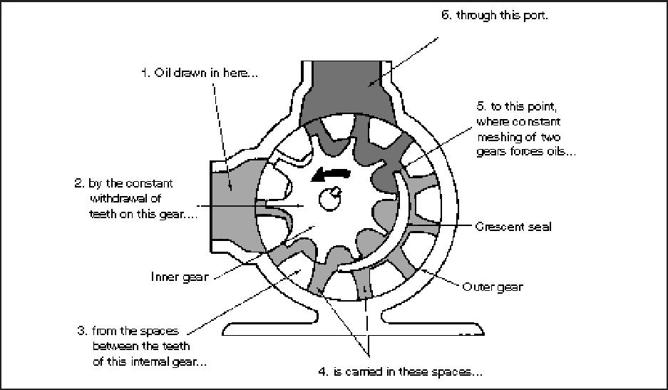 |
Internal Gear Pump. | ||||||||||||||||||||||||||||||||||||||||||||||||||||||||||||||||||||||||||||||||||||||||||||
|
External Gear Pump. | ||||||||||||||||||||||||||||||||||||||||||||||||||||||||||||||||||||||||||||||||||||||||||||
b. Vane Pumps. In a vane-type pump, a slotted rotor splined to a drive shaft rotates between closely fitted side plates that are inside of an elliptical- or circular shaped ring. Polished, hardened vanes slide in and out of the rotor slots and follow the ring contour by centrifugal force. Pumping chambers are formed between succeeding vanes, carrying oil from the inlet to the outlet. A partial vacuum is created at the inlet as the space between vanes increases. The oil is squeezed out at the outlet as the pumping chamber’s size decreases. Balanced design vane pumps all are fixed displacement. An unbalanced design can be built in either a fixed- or variable-displacement pump. Vane pumps have good efficiency and durability if operated in a clean system using the correct oil. They cover the low to medium-high pressure, capacity, and speed ranges. Package size in relation to output is small. A vane pump is generally quiet, but will whine at high speeds. |
|||||||||||||||||||||||||||||||||||||||||||||||||||||||||||||||||||||||||||||||||||||||||||||
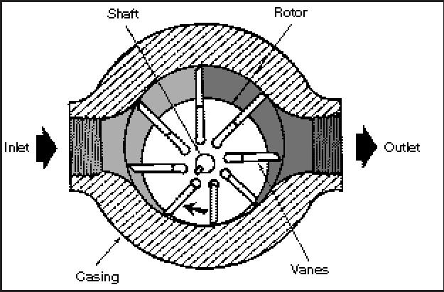 |
Unbalanced Vane Pump. | ||||||||||||||||||||||||||||||||||||||||||||||||||||||||||||||||||||||||||||||||||||||||||||
9-6. Pump Operation. The following paragraphs address some of the problems that could occur when a pump is operating: a. Overloading. One risk of overloading is the danger of excess torque on a drive shaft. b. Excess Speed. Running a pump at too high a speed causes loss of lubrication, which can cause early failure. If a needed delivery requires a higher drive speed than a pump's rating, use a higher displacement pump. Excess speed also runs a risk of damage from cavitation. c. Cavitation. Cavitation occurs where available fluid does not fill an existing space. It often occurs in a pump’s inlet when conditions are not right to supply enough oil to keep an inlet flooded. Cavitation causes the metal in an inlet to erode and the hydraulic oil to deteriorate quicker. Cavitation can occur if there is too much resistance in an inlet’s line, if a reservoir’s oil level is too far below the inlet, or if an oil’s viscosity is too high. It can also occur if there is a vacuum or even a slight positive pressure at the inlet. A badly cavitating pump has oil bubbles exploding in the void. The only way to be sure a pump is not cavitating is to check the inlet with a vacuum gauge. To prevent cavitation, keep the inlet clean and free of obstructions by using the correct length of an inlet’s line with minimum bends. Another method is to charge an inlet. The easiest way to do this is to flood it by locating the reservoir above the pump’s inlet. If this is not possible and you cannot create good inlet conditions, use a pressurized reservoir. Cavitation happens when the pressure in the fluid falls below the vapour pressure of THAT fluid at THAT temperature. In other words, when the physical conditions are right - a "change of state" spontaneously occurs, and the liquid turns to vapour, creating a vapour pocket or bubble that will then collapse very rapidly as it is exposed to higher surrounding pressure. The individual bubbles formed and then collapsing are very small, even microscopic, but they from and collapse very quickly and with great force and in great numbers. It's roughly analogous to condensation forming on your cold drink glass on a warm summer day. You have H2O, which can be solid (ice), liquid (water) or gas (water vapour ). Warm air can hold more water in suspension in vapour form than cold air. So if you take warm air full of water vapour and cool it, (like what happens when that warm, vapour laden air comes into contact with your cold drink glass) the water vapour will spontaneously change state from gas to liquid, and condensation forms (and runs down the glass and makes ring on the table if you didn't use a coaster!) So - in our pump (or any other part of the system for that matter - cavitation is not limited to the pump) if a pressure drop occurs (perhaps because of venturi effect or velocity or under changing conditions of temp and pressure) and the pressure drop occurs to a point below the vapour pressure of the fluid (whatever it may be) - voila - state change, vapour "bubble" and then when that vapour bubble encounters a region of higher pressure - it collapses with a "pop" and that's the noise you hear. d. Operating Problems. Pressure loss, slow operation, no delivery, and noise are common operating problems in a pump. (1) Pressure Loss. Pressure loss means that there is a high leakage path in a system. A badly worn pump could cause pressure loss. A pump will lose its efficiency gradually. The actuator speed slows down as a pump wears. However, pressure loss is more often caused by leaks somewhere else in a system (relief valve, cylinders, motors). (2) Slow Operation. This can be caused by a worn pump or by a partial oil leak in a system. Pressure will not drop, however, if a load moves at all. Therefore, hp is still being used and is being converted into heat at a leakage point. To find this point, feel the components for unusual heat. (3) No Delivery. If oil is not being pumped, a pump—
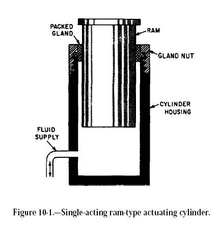
(4) Noise. If you hear any unusual noise, shut down a pump immediately. Cavitation noise is caused by a restriction in an inlet line, a dirty inlet filter, or too high a drive speed. Air in a system also causes noise. Air will severely damage a pump because it will not have enough lubrication. This can occur from low oil in a reservoir, a loose connection in an inlet, a leaking shaft seal, or no oil in a pump before starting. Also, noise can be caused by worn or damaged parts, which will spread harmful particles through a system, causing more damage if an operation continues. 10. Hydraulic Actuators A hydraulic actuator receives pressure energy and converts it to mechanical force and motion. An actuator can be linear or rotary. A linear actuator gives force and motion outputs in a straight line. It is more commonly called a cylinder but is also referred to as a ram, reciprocating motor, or linear motor. A rotary actuator produces torque and rotating motion. It is more commonly called a hydraulic motor or motor. 10-1. Cylinders. An actuating cylinder is a device that converts fluid power to linear, or straight line, force and motion. Since linear motion is a back-and-forth motion along a straight line, this type of actuator is sometimes referred to as a reciprocating, or linear, motor. The cylinder consists of a ram or piston operating within a cylindrical bore. Actuating cylinders may be installed so that the cylinder is anchored to a stationary structure and the ram or piston is attached to the mechanism to be operated, or the piston or ram may be anchored to the stationary structure and the cylinder attached to the mechanism to be operated. Actuating cylinders for pneumatic and hydraulic systems are similar in design and operation. Some of the variations of ram- and piston-type actuating cylinders are described in the following paragraphs. RAM-TYPE CYLINDERS Single-Acting Ram |
|||||||||||||||||||||||||||||||||||||||||||||||||||||||||||||||||||||||||||||||||||||||||||||
 |
Single-Acting Ram. | ||||||||||||||||||||||||||||||||||||||||||||||||||||||||||||||||||||||||||||||||||||||||||||
The single-acting ram (fig. 10-1) applies force in only one direction. The fluid that is directed into the cylinder displaces the ram and forces it outward, lifting the object placed on it. Since there is no provision for retracting the ram by fluid power, when fluid pressure is released, either the weight of the object or some mechanical means, such as a spring, forces the ram back into the cylinder. This forces the fluid back to the reservoir. The single-acting ram-type actuating cylinder is often used in the hydraulic jack. The elevators used to move aircraft to and from the flight deck and hangar deck on aircraft carriers also use cylinders of this type. In these elevators, the cylinders are installed horizontally and operate the elevator through a series of cables and sheaves. Fluid pressure forces the ram outward and lifts the elevator. When fluid pressure is released from the ram, the weight of the elevator forces the ram back into the cylinder. This, in turn, forces the fluid back into the reservoir. Double-Acting Ram |
|||||||||||||||||||||||||||||||||||||||||||||||||||||||||||||||||||||||||||||||||||||||||||||
 |
Double-Acting Ram. | ||||||||||||||||||||||||||||||||||||||||||||||||||||||||||||||||||||||||||||||||||||||||||||
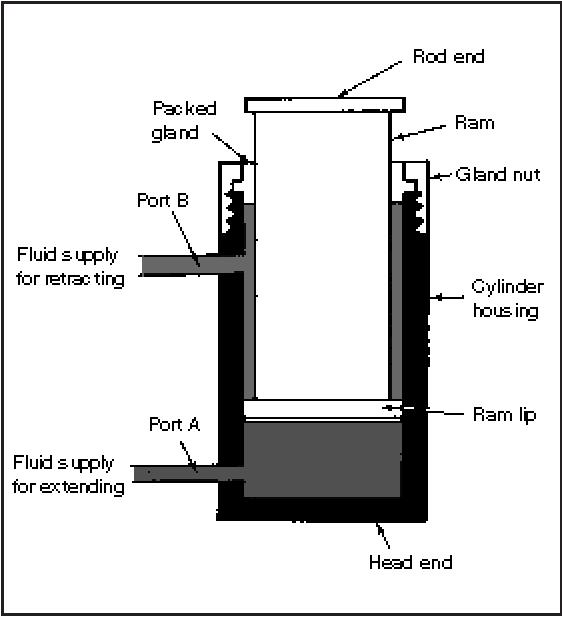
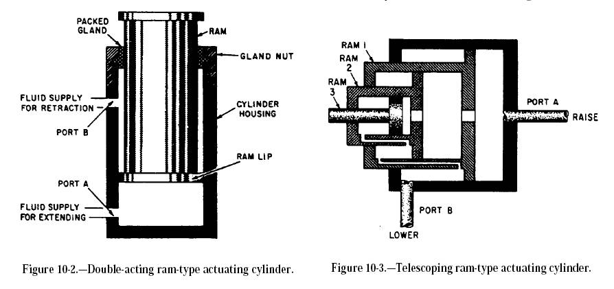
A double-acting ram-type cylinder is illustrated in figure 10-2. In this cylinder, both strokes of the ram are produced by pressurized fluid. There are two fluid ports, one at or near each end of the cylinder. Fluid under pressure is directed to the closed end of the cylinder to extend the ram and apply force. To retract the ram and reduce the force, fluid is directed to the opposite end of the cylinder. A four-way directional control valve is normally used to control the double-acting ram. When the valve is positioned to extend the ram, pressurized fluid enters port A (fig. 10-2), acts on the bottom surface of the ram, and forces the ram outward. Fluid above the ram lip is free to flow out of port B, through the control valve, and to the return line in hydraulic systems or to the atmosphere in pneumatic systems. Normally, the pressure of the fluid is the same for either stroke of the ram. Recall that force is equal to pressure times area (F= PA). Notice the difference of the areas upon which the pressure acts in figure 10-2. The pressure acts against the large surface area on the bottom of the ram during the extension stroke, during which time the ram applies force. Since the ram does not require a large force during the retraction stroke, pressure acting on the small area on the top surface of the ram lip provides the necessary force to retract the ram. Telescoping Rams Figure 10-3 shows a telescoping ram-type actuating cylinder. A series of rams is nested in the telescoping assembly. With the exception of the smallest ram, each ram is hollow and serves as the cylinder housing for the next smaller ram. The ram assembly is contained in the main cylinder assembly, which also provides the fluid ports. Although the assembly requires a small space with all the rams retracted, the telescoping action of the assembly provides a relatively long stroke when the rams are extended. An excellent example of the application of this type of cylinder is in the dump truck. It is used to lift the forward end of the truck bed and dump the load. During the lifting operation, the greatest force is required for the initial lifting of the load. |
|||||||||||||||||||||||||||||||||||||||||||||||||||||||||||||||||||||||||||||||||||||||||||||
 |
Telescoping ram-type actuating cylinder. | ||||||||||||||||||||||||||||||||||||||||||||||||||||||||||||||||||||||||||||||||||||||||||||
As the load is lifted and begins to dump, the required force becomes less and less until the load is completely dumped. During the raise cycle, pressurized fluid enters the cylinder through port A (fig. 10-3) and acts on the bottom surface of all three rams. Ram 1 has a larger surface area and, therefore, provides the greater force for the initial load, As ram 1 reaches the end of its stroke and the required force is decreased, ram 2 moves, providing the smaller force needed to continue raising the load. When ram 2 completes its stroke, a still smaller force is required. Ram 3 then moves outward to finish raising and dumping the load. Some telescoping ram-type cylinders are of the single-acting type. Like the single-acting ram discussed previously, these telescoping ram-type cylinders are retracted by gravity or mechanical force. Some hydraulic jacks are equipped with telescoping rams. Such jacks are used to lift vehicles with low clearances to the required height. Other types of telescoping cylinders, like the one illustrated in figure 10-3, are of the double acting type. In this type, fluid pressure is used for both the extension and retraction strokes. A four way directional control valve is commonly used to control the operation of the double-acting type. Note the small passages in the walls of rams 1 and 2. They provide a path for fluid to flow to and from the chambers above the lips of rams 2 and 3. During the extension stroke, return fluid flows through these passages and out of the cylinder through port B. It then flows through the directional control valve to the return line or reservoir. To retract the rams, fluid under pressure is directed into the cylinder through port B and acts against the top surface areas of all three ram lips. This forces the rams to the retracted position. The displaced fluid from the opposite side of the rams flows out of the cylinder through port A, through the directional control valve to the return line or reservoir. Dual Rams |
|||||||||||||||||||||||||||||||||||||||||||||||||||||||||||||||||||||||||||||||||||||||||||||
 |
Dual Rams. | ||||||||||||||||||||||||||||||||||||||||||||||||||||||||||||||||||||||||||||||||||||||||||||
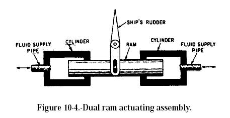
A dual ram assembly consists of a single ram with a cylinder at either end (fig. 10-4). Fluid can be directed to either cylinder, forcing the ram to move in the opposite direction. The ram is connected through mechanical linkage to the unit to be operated. A four-way directional control valve is commonly used to operate the dual ram. When the control valve is positioned to direct fluid under pressure to one of the cylinders (let’s say the left one), the ram is forced to the right. This Figure 10-4.-Dual ram actuating assembly. action displaces the fluid in the opposite cylinder. The displaced fluid flows back through the directional control valve to the return line or reservoir in hydraulic systems or to the atmosphere in pneumatic systems. Dual ram actuating assemblies are used in steering systems of most ships. In some systems, one assembly is used to actuate the rudder in either direction; while in other systems, two assemblies are used for the same purpose. PISTON-TYPE CYLINDERS An actuating cylinder in which the cross sectional area of the piston is less than one-half the cross-sectional area of the movable element is referred to as a piston-type cylinder. This type of cylinder is normally used for applications that require both push and pull functions. The piston type cylinder is the most common type used in fluid power systems. The essential parts of a piston-type cylinder are a cylindrical barrel, a piston and rod, end caps, and suitable seals. The end caps are attached to the ends of the barrel. These end caps usually contain the fluid ports. The end cap on the rod end contains a hole for the piston rod to pass through. Suitable seals are used between the hole and the piston rod to keep fluid from leaking out and to keep dirt and other contaminants from entering the barrel. The opposite end cap of most cylinders is provided with a fitting for securing the actuating cylinder to some structure. This end cap is referred to as the anchor end cap. The piston rod may extend through either or both ends of the cylinder. The extended end of the rod is normally threaded so that some type of mechanical connector, such as an eyebolt or a clevis, and a locknut can be attached. This threaded connection of the rod and mechanical connector provides for adjustment between the rod and the unit to be actuated. After the correct adjustment is made, the locknut is tightened against the connector to prevent the connector from turning. The other end of the connector is attached, either directly or through additional mechanical linkage, to the unit to be actuated. In order to satisfy the many requirements of fluid power systems, piston-type cylinders are available in various designs. Single-Acting Cylinder The single-acting piston-type cylinder is similar in design and operation to the single-acting ram-type cylinder. The single-acting piston-type cylinder uses fluid pressure to provide the force in one direction, and spring tension, gravity, compressed air, or nitrogen is used to provide the force in the opposite direction. |
|||||||||||||||||||||||||||||||||||||||||||||||||||||||||||||||||||||||||||||||||||||||||||||
 |
Single-acting, spring-loaded, piston-type actuating cylinder. | ||||||||||||||||||||||||||||||||||||||||||||||||||||||||||||||||||||||||||||||||||||||||||||
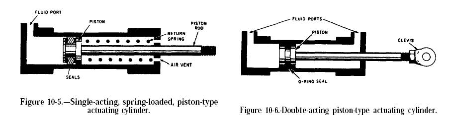
Figure 10-5 shows a single-acting, spring-loaded, piston-type actuating cylinder. In this cylinder the spring is located on the rod side of the piston. In some spring-loaded cylinders the spring is located on the blank side, and the fluid port is on the rod side of the cylinder. A three-way directional control valve is normally used to control the operation of the single-acting piston-type cylinder. To extend the piston rod, fluid under pressure is directed through the port into the cylinder (fig. 10-5). This pressure acts on the surface area of the blank side of the piston and forces the piston to the right. This action moves the rod to the right, through the end of the cylinder, thus moving the actuated unit in one direction. During this action, the spring is compressed between the rod side of the piston and the end of the cylinder. The length of the stroke depends upon the physical limits within the cylinder and the required movement of the actuated unit. To retract the piston rod, the directional control valve is moved to the opposite working position, which releases the pressure in the cylinder. The spring tension forces the piston to the left, retracting the piston rod and moving the actuated unit in the opposite direction. The fluid is free to flow from the cylinder through the port, back through the control valve to the return line in hydraulic systems or to the atmosphere in pneumatic systems. The end of the cylinder opposite the fluid port is vented to the atmosphere. This prevents air from being trapped in this area. Any trapped air would compress during the extension stroke, creating excess pressure on the rod side of the piston. This would cause sluggish movement of the piston and could eventually cause a complete lock, preventing the fluid pressure from moving the piston. The spring-loaded cylinder is used in arresting gear systems on some models of carrier aircraft. To raise (retract) the arresting hook, fluid pressure is directed through the arresting hook control valve to the rod side of the cylinder. This force moves the piston, which, through the rod and mechanical linkage, retracts the arresting hook. The arresting hook extends when fluid pressure is released from the rod side of the cylinder, allowing the spring to expand. Leakage between the cylinder wall and piston is prevented by adequate seals. The piston in figure 10-5 contains O-ring seals. Double-Acting Cylinder Most piston-type actuating cylinders are double-acting, which means that fluid under pressure can be applied to either side of the piston to apply force and provide movement. One design of the double-acting cylinder is shown in figure 10-6. This cylinder contains one piston and piston rod assembly. The stroke of the piston and piston rod assembly in either direction is produced by fluid pressure. The two fluid ports, one near each end of the cylinder, alternate as inlet and outlet ports, depending on the direction of flow from the directional control valve. This actuator (fig. 10-6) is referred to as an unbalanced actuating cylinder because there is a difference in the effective working areas on the two sides of the piston. Therefore, this type of cylinder is normally installed so that the blank side of the piston carries the greater load; that is, the cylinder carries the greater load during the piston rod extension stroke. A four-way directional control valve is normally used to control the operation of this type of cylinder. The valve can be positioned to direct fluid under pressure to either end of the cylinder and allow the displaced fluid to flow from the opposite end of the cylinder through the control valve to the return line in hydraulic systems or to the atmosphere in pneumatic systems. |
|||||||||||||||||||||||||||||||||||||||||||||||||||||||||||||||||||||||||||||||||||||||||||||
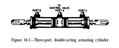 |
Three-port, double-acting cylinder. | ||||||||||||||||||||||||||||||||||||||||||||||||||||||||||||||||||||||||||||||||||||||||||||
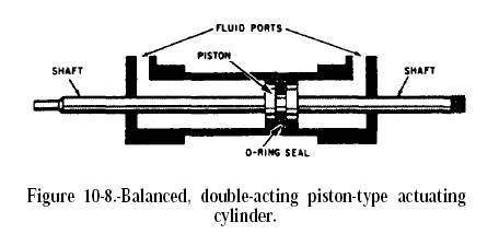 |
Balanced double-acting cylinder. | ||||||||||||||||||||||||||||||||||||||||||||||||||||||||||||||||||||||||||||||||||||||||||||
There are applications where it is necessary to move two mechanisms at the same time. In this case, double-acting piston-type actuating cylinders of different designs are required. See figures 10-7 and 10-8. Figure 10-7 shows a three-port, double-acting piston-type actuating cylinder. This actuator contains two pistons and piston rod assemblies. Fluid is directed through port A by a four-way directional control valve and moves the pistons outward, thus moving the mechanisms attached to the pistons’ rods. The fluid on the rod side of each piston is forced out of the cylinder through ports B and C, which are connected by a common line to the directional control valve. The displaced fluid then flows through the control valve to the return line or to the atmosphere. When fluid under pressure is directed into the cylinder through ports B and C, the two pistons move inward, also moving the mechanisms attached to them. Fluid between the two pistons is free to flow from the cylinder through port A and through the control valve to the return line or to the atmosphere. The actuating cylinder shown in figure 10-8 is a double-acting balanced type. The piston rod extends through the piston and out through both ends of the cylinder. One or both ends of the Figure 10-8.-Balanced, double-acting piston-type actuating cylinder. piston rod may be attached to a mechanism to be operated. In either case, the cylinder provides equal areas on each side of the piston. Therefore, the same amount of fluid and force is used to move the piston a certain distance in either direction. Tandem Cylinders |
|||||||||||||||||||||||||||||||||||||||||||||||||||||||||||||||||||||||||||||||||||||||||||||
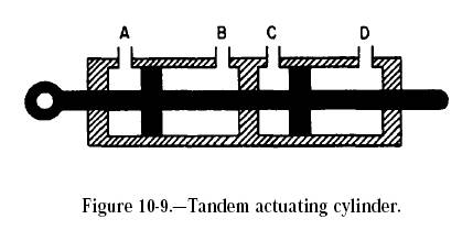 |
Tandem Cylinder. | ||||||||||||||||||||||||||||||||||||||||||||||||||||||||||||||||||||||||||||||||||||||||||||
A tandem actuating cylinder consists of two or more cylinders arranged one behind the other but designed as a single unit (fig. 10-9). This type of actuating cylinder is used in applications that require two or more independent systems; for example, power-operated flight control systems in naval aircraft. The flow of fluid to and from the two chambers of the tandem actuating cylinder is provided from two independent hydraulic systems and is controlled by two sliding spool directional control valves. In some applications, the control valves and the actuating cylinder are two separate units. In some units, the pistons (lands) of the two sliding spools are machined on one common shaft. In other applications, the valves and the actuator are directly connected in one compact unit. Although the two control valves are hydraulically independent, they are interconnected mechanically. In other units, the two sliding spools are connected through mechanical linkages with a synchronizing rod. In either case, the movement of the two sliding spools is synchronized, thus equalizing the flow of fluid to and from the two chambers of the actuating cylinder. Since the two control valves operate independently of each other as far as hydraulic pressure is concerned, failure of either hydraulic system does not render the actuator inoperative. Failure of one system does reduce the output force by one-half; however, this force is sufficient to permit operation of the actuator. 10-2. Cylinder Maintenance. Hydraulic cylinders are compact and relatively simple. The key points to watch are the seals and pivots. The following lists service tips in maintaining cylinders:
11. Valves Valves are used in hydraulic systems to control the operation of the actuators. Valves regulate pressure by creating special pressure conditions and by controlling how much oil will flow in portions of a circuit and where it will go. The three categories of hydraulic valves are pressure-control, flow- (volume-) control, and directional-control. Some valves have multiple functions, placing them into more than one category. Valves are rated by their size, pressure capabilities, and pressure drop/flow. Simple Valves: |
|||||||||||||||||||||||||||||||||||||||||||||||||||||||||||||||||||||||||||||||||||||||||||||
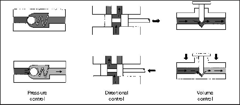 |
Simple Valves. | ||||||||||||||||||||||||||||||||||||||||||||||||||||||||||||||||||||||||||||||||||||||||||||
11-1. Pressure-Control Valves. A pressure-control valve may limit or regulate pressure, create a particular pressure condition required for control, or cause actuators to operate in a specific order. Most pressure-control valves are classified as normally closed. This means that flow to a valve's inlet port is blocked from an outlet port until there is enough pressure to cause an unbalanced operation. a. Relief Valves. Relief valves are the most common type of pressure-control valves. The relief valves’ function may vary, depending on a system's needs. They can provide overload protection for circuit components or limit the force or torque exerted by a linear actuator or rotary motor. b. Pressure-Reducing Valves. These valves limit pressure on a branch circuit to a lesser amount than required in a main circuit. c. Sequence Valves. Sequence valves control the operating sequence between two branches of a circuit. 11-2. Directional-Control Valves. Directional-control valves also control flow direction. However, they vary considerably in physical characteristics and operation. The valves may be a
Directional-control valves may also be classified according to the method used to actuate the valve element. A poppet-type valve is usually hydraulically operated. A rotary-spool type may be manually (lever or plunger action), mechanically (cam or trip action), or electrically (solenoid action) operated. A sliding-spool type may be manually, mechanically, electrically, or hydraulically operated, or it may be operated in combination. Directional-control valves may also be classified according to the number of positions of the valve elements or the total number of flow paths provided in the extreme position. For example, a three-position, four-way valve has two extreme positions and a center or neutral position. In each of the two extreme positions, there are two flow paths, making a total of four flow paths. Spool valves are popular on modern hydraulic systems because they
Spool valves, however, require good maintenance. Dirty oil will damage the mating surfaces of the valve lands, causing them to lose their accuracy. Dirt will cause these valves to stick or work erratically. Also, spool valves must be accurately machined and fitted to their bores. Four-Way Valves. Four-way, directional-control valves are used to control the direction of fluid flow in a hydraulic circuit, which controls the direction of movement of a work cylinder or the rotation of a fluid motor. These valves are usually the sliding-spool type. A typical four-way, directional-control valve has four ports:
Open-center valves are used when a work cylinder does not have to be held in position by pressure and where power is used to perform a single operation. These valves also avoid shock to a system when a valve spool is moved from one position to another, since in the intermediate position, pressure is temporarily relieved by liquid passing from a pump directly to the reservoir. 11-3. Flow-Control Valves. Flow-control valves are used to control an actuator’s speed by metering flow. Metering is measuring or regulating the flow rate to or from an actuator. A water faucet is an example of a flow-control valve. Flow rate varies as a faucet handle is turned clockwise or counterclockwise. In a closed position, flow stops. Many flow-control valves used in fluid-powered systems are similar in design and operation to a water faucet’s. In hydraulic circuits, flow-control valves are generally used to control the speed of hydraulic motors and work spindles and the travel rates of tool heads or slides. Flow-control valves incorporate an integral pressure compensator, which causes the flow rate to remain substantially uniform regardless of changes in workload. A non-pressure-compensated flow control, such as a needle valve or fixed restriction, allows changes in the flow rate when pressure drop through it changes. Variations of the basic flow-control valves are the flow-control-and-check valves and the flow-control-and-overload relief valves. 12. Accumulators Accumulators. Like an electrical storage battery, a hydraulic accumulator stores potential power, in this case liquid under pressure for future conversion into useful work. This work can include operating cylinders and fluid motors, maintaining the required system pressure in case of pump or power failure, and compensating for pressure loss due to leakage. Accumulators can be employed as fluid dispensers and fluid barriers and can provide a shock-absorbing (cushioning) action. 13. Assembly, Troubleshooting & Maintenance 13-1. Good Assembly Practices Most important – cleanliness. All cylinder, valve, pump and hose connections should be sealed and/or capped until just prior to use. Air hoses can be used to clean fittings and other system components. However, the air supply must be filtered and dry to prevent contamination of the parts. Examine pipe fittings and hose assemblies prior to use to be certain that burrs, dirt and/or scale are not present. All pipe and tubing ends should be reamed to prevent restriction and turbulent flow. Do not use Teflon tape on straight thread connections. When installing V-belt pulleys on pumps or motors, line up both pulleys as closely as possible. Always install the pulleys with a minimum amount of overhang as close to the pump or motor face as possible. This increases bearing service life. 13-2. Troubleshooting. Causes of Improper Operations. If improper operation does occur, the cause can generally be traced to one of the following:
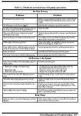
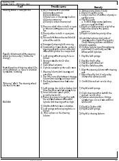
Trouble shooting general
For more EXCELLENT troubleshooting information, see the following pdf files I compiled from the US Army Hydraulics Manual and Danfoss Hydraulics Manual. |
|||||||||||||||||||||||||||||||||||||||||||||||||||||||||||||||||||||||||||||||||||||||||||||
 |
Army Hydraulic Troubleshooting charts | ||||||||||||||||||||||||||||||||||||||||||||||||||||||||||||||||||||||||||||||||||||||||||||
 |
Danfoss Hydraulic Troubleshooting charts | ||||||||||||||||||||||||||||||||||||||||||||||||||||||||||||||||||||||||||||||||||||||||||||
13-3. Aeration / Cavitation The following are candidates for the formation of air in a system.
Effects Aeration can be in many forms; large bubbles, foam or in various degrees of suspension. It usually causes pump noise (cavitation). Small bubbles cause extreme and rapid ring wear, with corresponding vane tip wear. Larger bubbles cause vanes to collapse and pound. Causes and Cures
13-4 Cause Of Leaks Almost all hydraulic system leaks occurring after extended service result from three conditions:
13-5 Combatting Shock And Vibration Many things can be done to minimize leakage from loose fittings and connectors subject to shock and vibration:
13-6 Reducing Dynamic Seal Wear
13-7 Draining the System Draining The System. The system should be started and fluid heated before draining. This will lower the time it takes to drain the system and allow impurities suspended in the fluid to be removed. It is desirable to remove all fluid from the system. Bleeding of the fluid at the lowest point in the system will help in most cases. Systems which have accumulated deposits that were not removed during draining must be flushed with a light viscosity fluid. The fluid should contain a rust inhibitor to protect metal surfaces against rust formation after draining. When hydraulic fluid is added to replenish the system, it should be pumped through a 25 micron filter. If such a filter is not available, a funnel with a fine wire screen (200 mesh or finer) can be used. It is important that fluid be clean and free of all substances which will cause improper operation. 13-8. Maintenance Three simple maintenance procedures have the greatest effect on hydraulic system performance, efficiency and life.
|
|||||||||||||||||||||||||||||||||||||||||||||||||||||||||||||||||||||||||||||||||||||||||||||
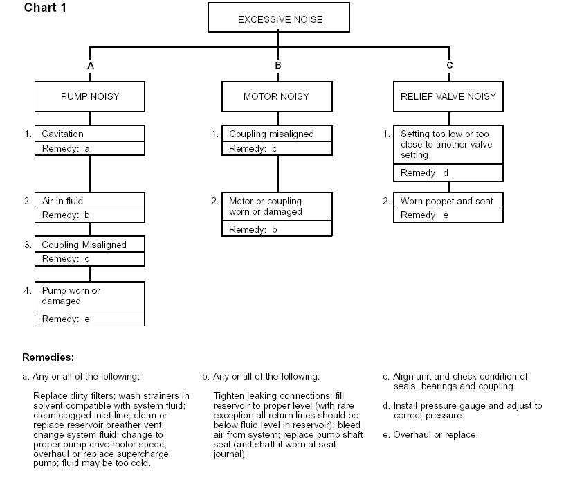 |
13-9 Noise diagnosis: | ||||||||||||||||||||||||||||||||||||||||||||||||||||||||||||||||||||||||||||||||||||||||||||
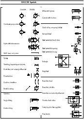 |
Circuit Diagrams and Symbols Click on the image to open a .pdf file of standard international hydraulic circuit symbols |
||||||||||||||||||||||||||||||||||||||||||||||||||||||||||||||||||||||||||||||||||||||||||||
|
|||||||||||||||||||||||||||||||||||||||||||||||||||||||||||||||||||||||||||||||||||||||||||||
|