 |
The Driveshaft Bible By Bill "BillaVista" Ansell |
IntroductionIn my quest to build my 1-ton rock buggy, The Wolf, as tough as possible, I upgraded my driveline from stock Dana 20 transfer case and hacked-together junkyard 1/2 ton pickup driveshaft to Advance Adapters D20 32 Spline Output and the famous 1 TON 1350 CV driveshaft from Jess at High Angle Driveline. But before I explain why, how, what else Jess can do, and why High Angle Driveline build the best shafts in the business, I'm going to take you through a little (OK, a LOT!) of driveshaft tech. Why? For 3 reasons: First, it's important we have a common understanding and language to use, so there is no confusion or misunderstanding (especially in this sport/hobby, where confusion, rumour, legend, and misunderstanding often run rampant - driveshafts being no exception); |
 |
||
Second, because I'm just a super-geek when it comes to accuracy and terminology - you already know this if you've been reading my articles for a while now. Sure, it often get's me beaten up at club event's and four wheeling trips......but the guys really love me, I know they do ;-) Third, and most importantly, it is because I am committed to bringing my readers only the very best in tech articles and product reviews. I don't do cheesy 2 pic, unwrap, install, "call it good" articles, where I claim the product is superb, even though I clearly know nothing about it. I am committed to providing you with the technical information and facts to make informed decisions, and in so doing, I hope to prove to you that I know a bit about what I'm talking about, and that my opinions, especially on products I recommend, are based on solid knowledge, fact, and experience. There's a lot to cover, so this article is arranged in 5 broad sections, further subdivided as follows:
Part 1 - Definitions and Operating Descriptions:There are some very common misconceptions out there about driveshafts, many of which revolve around terminology. To help alleviate this, I offer the following information: Universal Joints: A universal joint is defined as a "shaft coupling capable of transmitting rotation from one shaft to another not collinear with it." In other words, it is a mechanical device that transmits torque / rotary motion between two shafts that are not in a straight line. There are 2 types, the: 1) Cardan style universal joint; and the 2) Constant velocity universal joint We shall explore them both separately: Cardan Style Universal Joint |
|||
 |
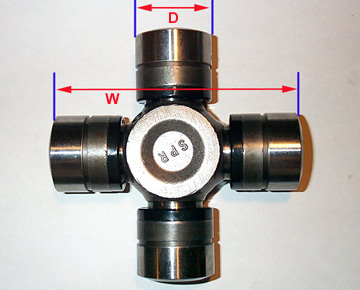
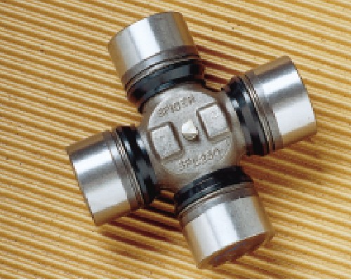
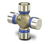
The most common type we encounter is the cardan style universal joint, developed by Spicer, and pictured to the left. This is the familiar "cross and caps" style universal joint, often just referred to as a "U-joint". Remember though, that technically it is a cardan style universal joint. | |||||||||||||||||||||||||||||||||||||||||||||
The way the cardan style universal joint works is as follows (and this is very important to understand): First - why do we need to use a universal joint in the first place? The answer is easy, and can be surmised from the above definition. |
||||||||||||||||||||||||||||||||||||||||||||||
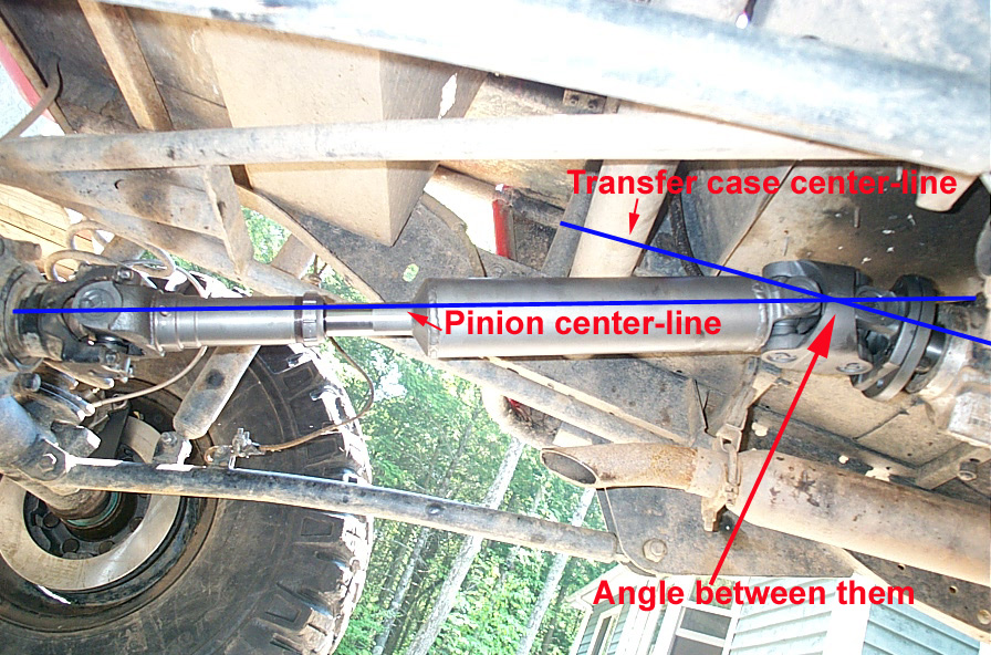 |
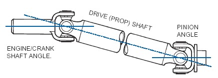
It is because we need to transmit torque from the transfer case to the axle pinion, and of course, the transfer case and pinion are not collinear - they are not in a straight line. The t-case is above the pinion (obviously)! Therefore there is an angle between them. In order to transmit torque or rotation between 2 shafts that are at an angle, we must use a universal joint. In the automotive driveshaft world, 99% of the time that means we use a cardan (cross) style universal joint. | |||||||||||||||||||||||||||||||||||||||||||||
 |
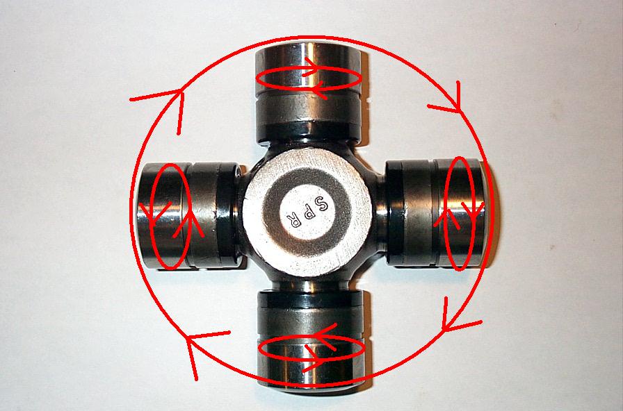
Because of the way the cardan style universal joint operates when the 2 shafts it joins lie at an angle (see pic to left - the joint cross or body rotates about it's center, while at the same time the caps rotate around their trunnions), the result is that the joint follows an elliptical, rather than a circular path. | |||||||||||||||||||||||||||||||||||||||||||||
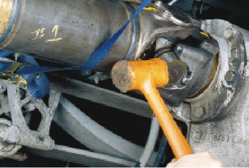
| To visualize how this occurs, look down the length of a rear driveshaft at the U-joint in the transfer case yoke. If the pinion end of the driveshaft were unbolted from the differential and lowered to the floor, it would create a severe angle in the forward U-joint. If the shaft were then turned by hand, you’d then be able to see that the two bearing caps on the U-joint center cross attached to the driveshaft rotate in one plane while the two attached to the transfer case yoke rotate in a different plane. All the while the center cross is swiveling back and forth with each revolution. | ||||||||||||||||||||||||||||||||||||||||||||||
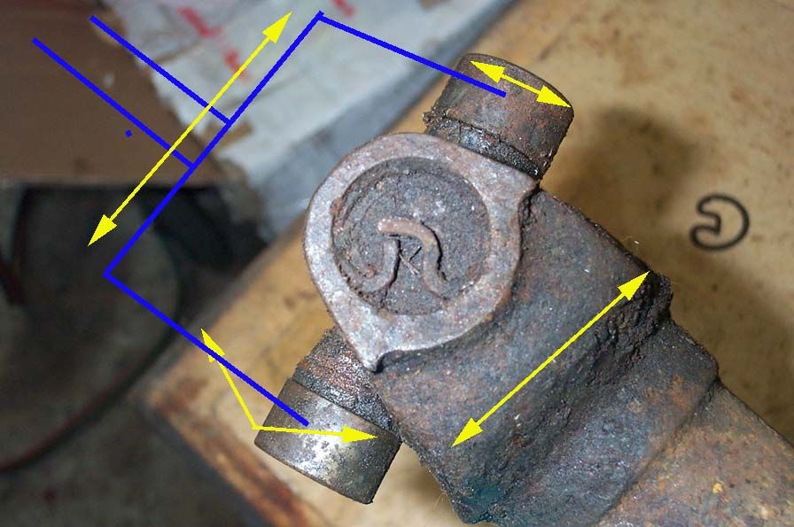 |
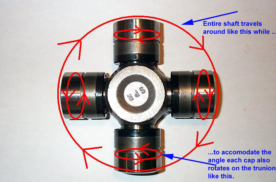
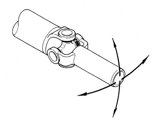
The best way to illustrate this is to hold 2 shafts coupled by a U-joint in your hand and rotate them- you will quickly see exactly what I mean. The crude drawing to the left may also serve to illustrate what is happening. I have drawn in blue a representation of a second yoke on the other side of the joint from the actual yoke pictured. Now, what happens is, the real yoke and the blue yoke, connected by the U-joint, both rotate around in the direction indicated by the long double-headed arrows. To accommodate the angle between the 2 yokes, the bearing caps each rotate around on their respective trunnions, as indicated by the short double-headed arrow. The result of the combination of these two motions is the U-joint swiveling back and forth each revolution, in a sort of see-saw back-and-forth motion, as indicated by the "V" shaped double-headed arrow. Ultimately, this leads to the elliptical path of the bearing caps, when viewed longitudinally down the shafts. | |||||||||||||||||||||||||||||||||||||||||||||
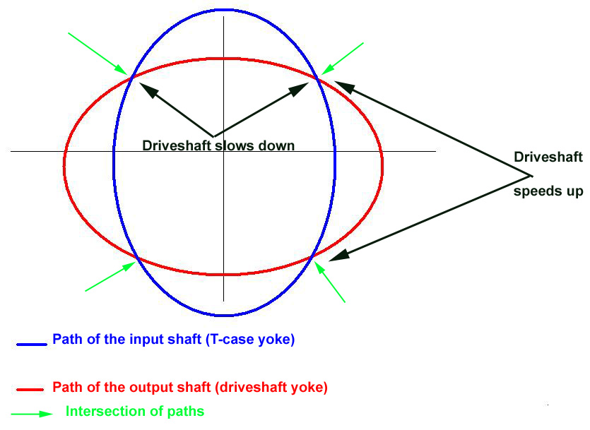 |
If you drew what’s happening on paper (and of course I have done that for you :-), the two bearing caps in the transfer case yoke would appear to be traveling in an elliptical (oval) shaped path as viewed down the length of the driveshaft (blue ellipse). Or, from the other point of view, the two bearing caps on the driveshaft would appear to be traveling an elliptical path if viewed from the transfer case (red ellipse). It is this difference in geometry that causes the driven shaft to change speed with respect to the driving shaft. | |||||||||||||||||||||||||||||||||||||||||||||
So, we have two different shafts, connected by a universal joint operating at an angle. Because of this, the ends of the U-joint in each of the yokes in the 2 different shafts (the t-case output yoke, and the yoke at the transfer case end of the driveshaft) both travel in elliptical paths, but the paths are 90° offset (out of phase) from one-another. In the pic to the left, the blue ellipse represents the path of the input shaft (t-case yoke) and the red ellipse represents the path of the output shaft (driveshaft yoke). Because the 2 shafts are connected to opposite bearing caps, their elliptical paths are offset 90°, as can be seen in the pic. Now, the problem is, the t-case output is driven from the crankshaft by gears and/or chain drive at a fixed rate (angular velocity) - let's say 1000 rpm for example. Of course, because the driveshaft is mechanically connected to the t-case output, it also must be rotating at 1000 rpm. In the pic, the green arrows show where the two elliptical paths cross, the points of intersection. At these points, the 2 shafts must be in the same place at the same time (otherwise the assembly would come apart.) In order for this to happen, you can see that at times the driveshaft's elliptical path (red ellipse) is longer than the t-case yokes (blue ellipse) and vice versa. So, in order for the assembly to remain together and driven at a fixed rpm, the driveshaft must have to speed up and slow down at different points along it's path in order to match the t-case yoke that is being driven at 1000 rpm. The black arrows show where this happens. In this case, the driveshaft will speed up and slow down a total of 4 times per revolution. That is, it speeds up, slows down, speed up, slows down, then repeats. This is the reason why we say a cardan style universal joint transmits rotation/torque with a "variation in angular velocity between the input and output shafts". This speeding up and slowing down can cause vibration of the driveshaft and significant wear on the universal joints if not properly accounted for in the driveshafts design. This "accounting for" is what we call driveline geometry and will be discussed in great detail in part 2. For now, remember that a U-joint must be used because there's an angle between the t-case and pinion (and often a very big angle in the case of lifted 4x4s - which is why this whole driveshaft business is so important to us in the first place). When a U-joint is used, and operates at an angle, the bearing caps on the input and output shafts will describe elliptical paths offset by 90° from one-another because of the difference in geometry between the two opposing bearing caps in the U-joint. Since they travel in elliptical paths, and yet must remain fixed together driven at a constant rpm the driveshaft must therefore speed up and slow down twice each per revolution. This difference in angular velocity between the 2 shafts causes noise, vibration, and U-joint wear, and must be accounted for in proper driveshaft design. The speed changes are not great when the angle is less than a few degrees, but as the operating angle of the joint increases so do the cyclic vibrations of the driven shaft as well as the back and forth motion in the joint itself. Constant-Velocity (CV) Universal Joint: |
||||||||||||||||||||||||||||||||||||||||||||||
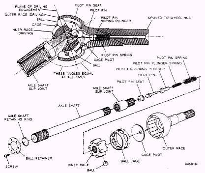 |
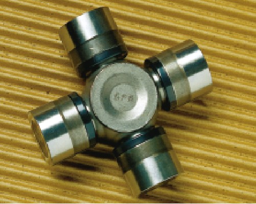
In marked contrast to the cardan style universal joint, a true constant-velocity (CV) universal joint is one that transmits torque/rotation with an angular velocity ratio of unity between input and output shafts. In other words, even at an angle, the input and output shafts travel at the same (Constant) speed (Velocity) hence the name - Constant Velocity. CV universal joints are not common in 4x4 driveshafts, but are very common in front wheel drive car half-shafts (axles). The pic to the left shows a very common style of CV joint, the Rzeppa joint, invented in 1920 by a Dana engineer named Alfred H. Rzeppa | |||||||||||||||||||||||||||||||||||||||||||||
Their common use in fwd cars is because the joints in the half shafts must accommodate being driven at high speeds for long times as well as changing compound angles due to the front wheels being steered and the front wheels cycling up and down with the suspension. As such, the inner and outer joints in a fwd car half shaft often operate at different angles. Whenever the wheels are turned the outer joint runs at a much higher angle than the inner joint. This upsets the offsetting relationship between inner and outer joint angles that’s a necessary requirement for ordinary U-joints. What’s more, the front wheels are required to steer at angles of up to 45 degrees—which puts too much strain on a U-joint. A CV joint, by comparison, always splits the operating angle in half so the driven shaft turns at the exact same speed as the input shaft. So no matter what the joint angle, there are no changes in speed -- thus the name "constant velocity." Driveshafts: A driveshaft is a device that connects the transfer case to the axles, transmitting torque from the engine to the driving wheels. It is also called a propeller shaft or prop-shaft for short (mostly by Brits and Aussies). Virtually all driveshafts (certainly all that I know of) fit into one of two often misunderstood broad categories. They are: EITHER Cardan-style universal joint driveshafts, subdivided into:
|
||||||||||||||||||||||||||||||||||||||||||||||
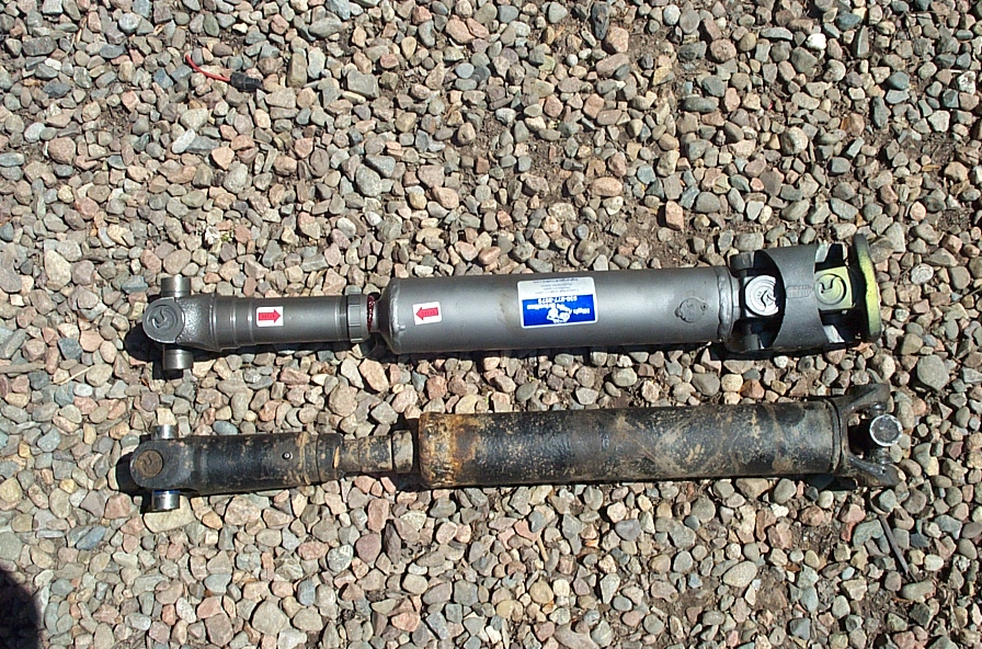 |
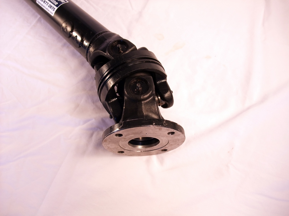
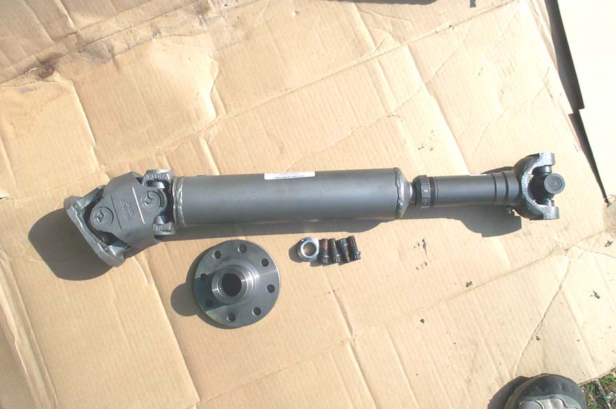
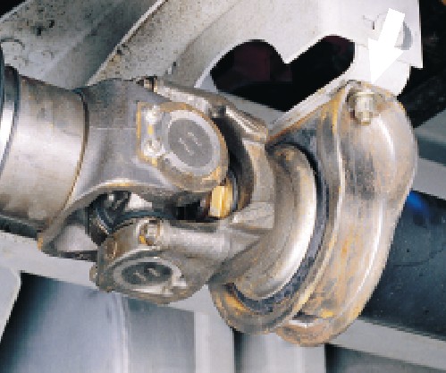
Pictured at left - double-cardan-style
universal joint shaft on top (my new High
Angle Driveline shaft) and a single-cardan-style universal joint
shaft (the junk I took out!)
Note that, as you would expect, the double-cardan shaft has one end (the transfer case end) that has a joint that contains, two cardan-style U-joints - forming the "double-cardan" portion. More on this later. |
|||||||||||||||||||||||||||||||||||||||||||||
OR Constant Velocity (CV) joint style driveshafts. This is an important distinction, if only academically. You see, true CV joint driveshaft are rare in 4x4 driveshafts (some earlier Jeeps came with GKN CV style front driveshafts that were tiny and weak) |
||||||||||||||||||||||||||||||||||||||||||||||
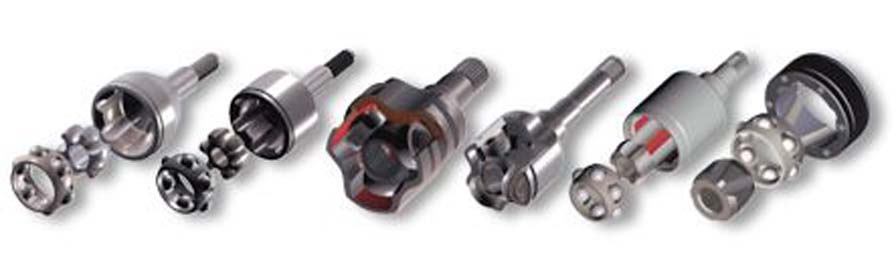 |
CV joints are, however, extremely common in FWD car half shafts (half axle shafts). Pictured at left are some GKN half-shaft CV joints. Virtually all modern cars have them. Virtually all are made by GKN's automotive driveshaft group. | |||||||||||||||||||||||||||||||||||||||||||||
There are many different types of CV joint, including Fixed Ball, Single Roller Tripod Plunging Joint, Ball Plunging Joint, etc. You can read about them at http://www.gkndriveline.com/ None have anything to do with our needs and heavy-duty 4x4 driveshafts. WHAT???? You cry. But everyone's always talking about CV driveshafts - heck the title of your own article is "1 Ton CV driveshaft" you hypocrite! You're right - you see, the very common double-cardan-style universal joint shaft (pictured above, upper shaft in pic), is properly called a "near constant velocity, double-cardan-style universal joint shaft." (incidentally, this "velocity" we keep referring to is the angular velocity of the joint in the shaft). Now, what has happened is that because "near constant velocity, double-cardan-style universal joint shaft" is such a huge mouthful, it has become common practice to drop the "near" , "double-cardan-style", and "universal joint" and what we are left with is common convention leading to a double-cardan-style universal joint shaft simply being referred to as a CV shaft. There - now you know the truth, and you can amaze your friends (or getting soundly beaten by them for being a nerdy smart-ass) at the next trail-side campfire! So, we know that true CV joint driveshafts are of no interest to us, so forget them now. That leaves us with either single or double cardan style driveshafts. The latter, I shall bow to convention, an henceforth refer to them as CV driveshafts, simply because everyone does. Now, whether a 4x4s driveshaft is single cardan (also called "regular' or "single-joint" or simply "U-joint) or CV, there is one more distinction to make. All driveshaft's must have some way of changing length, allowing the driveshaft to shorten or lengthen as required, to accommodate suspension movement. This is because suspension movement will cause the distance between the output of the transfer case and the yoke on the axles pinion to change somewhat. How much the distance changes, and therefore how much "accommodation" you need in your driveshaft will depend on a lot of different factors, including suspension geometry, amount of wheel travel, whether the diff on the axle is centered or offset, etc. For example, a 4 link coil sprung rear axle with center limiting strap will require significantly less length change accommodation than a soft leaf-spring-over-axle front axle with shackle reversal, offset diff, and no limit straps. The former may require only an inch or 2, the latter many inches. The only way to know for sure is to flex the suspension and measure. The 2 common methods of accommodating this length change, or slip, are: Type 1 - Slip-yoke shaft. This style is a very common late model rear driveshaft factory style. It comes stock in a great number of 4x4s, including Jeeps, Chevy's, and many others. The slip-yoke is an internally splined tube that slips into the rear output of the transfer case. As the name implies, the slip yoke slips in and out of the transfer case output housing, to accommodate driveshaft length change. generally, this type is not favoured by the hardcore crowd as it's drawbacks generally include:
|
||||||||||||||||||||||||||||||||||||||||||||||
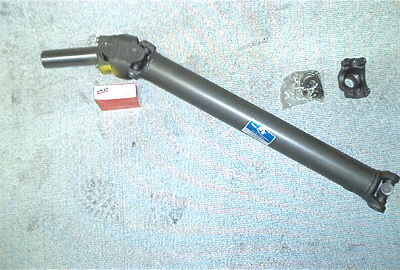 |
That said, High Angle Driveline can build you a 1350 1 Ton CV slip-yoke driveshaft. The pic to the left is just such a shaft. | |||||||||||||||||||||||||||||||||||||||||||||
| Type 2 - Slip-member shaft. This style is common on trucks and 4x4s, especially older trucks, and is the most desirable type. They use a splined section incorporated in the shaft itself, called the slip-member, which allows the shaft to change length. | ||||||||||||||||||||||||||||||||||||||||||||||
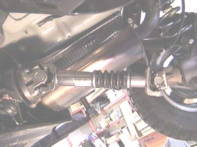
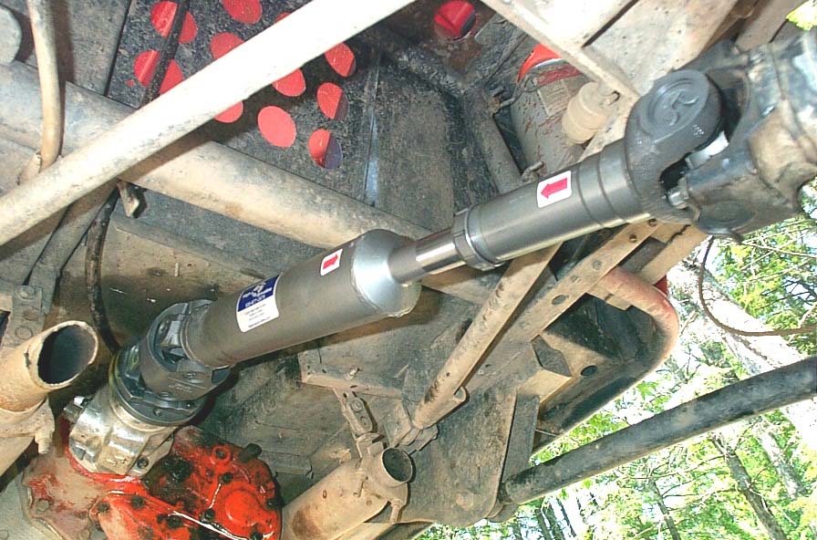 |
The pic to the left is my new shaft installed, which is a slip-member style shaft. The slip-member is easily visible between the red arrows. | |||||||||||||||||||||||||||||||||||||||||||||
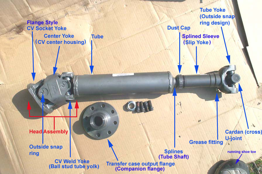 |
Now that we know all about the different types of shafts, this picture illustrates the names of the various parts of the drive shaft. Where there is more than one common name, the alternate names are shown in brackets. | |||||||||||||||||||||||||||||||||||||||||||||
Driveshaft U-joint Series / SizesSo we know all about the different types, and all the parts, the last thing we need to know before we can fully and accurately describe and talk about driveshafts is the relative size (and therefore strength), normally determined by and referenced to, the size (series) of the U-joints used in the driveshaft. A U-joint "series" is a number that describes a group of cardan style universal joints by common dimensional grouping. A series number is not an actual specific part number. The common U-joint series used in light truck and 4x4 driveshaft construction, with dimensions listed corresponding to the diagram are: |
||||||||||||||||||||||||||||||||||||||||||||||
 |
|
|||||||||||||||||||||||||||||||||||||||||||||
Glossary
So now that we know all the terms and definitions regarding Driveshafts, what else do we need to know to get the best, world class, bulletproof driveshaft under our truck? Well - the answer is ....depends. It depends on what kind of person you are. If you just want the job done, so you can get behind the wheel, the answer is NOTHING. You simply call up Jess at High Angle Driveline @ (530) 877-2875 and have a nice chat with him about your needs. He will help you with whatever you need, discuss your options with you, and be pleased to talk to you about driveshaft tech, and his customer service is second to none. However - if you're a tech-geek like me - you want to know more. Part 2 - Driveshaft GeometryProper driveshaft geometry is critical to getting the most from your driveshafts. Improper geometry will cause vibration, excessive wear, and premature failure. Even the best driveshaft in the world will suck if it is not installed with proper geometry. We also need to know about proper geometry in order to select the best type of shaft for our application. Before we discuss geometry, a couple more definitions of some terms are in order. For the purposes of this article: Terms |
||||||||||||||||||||||||||||||||||||||||||||||
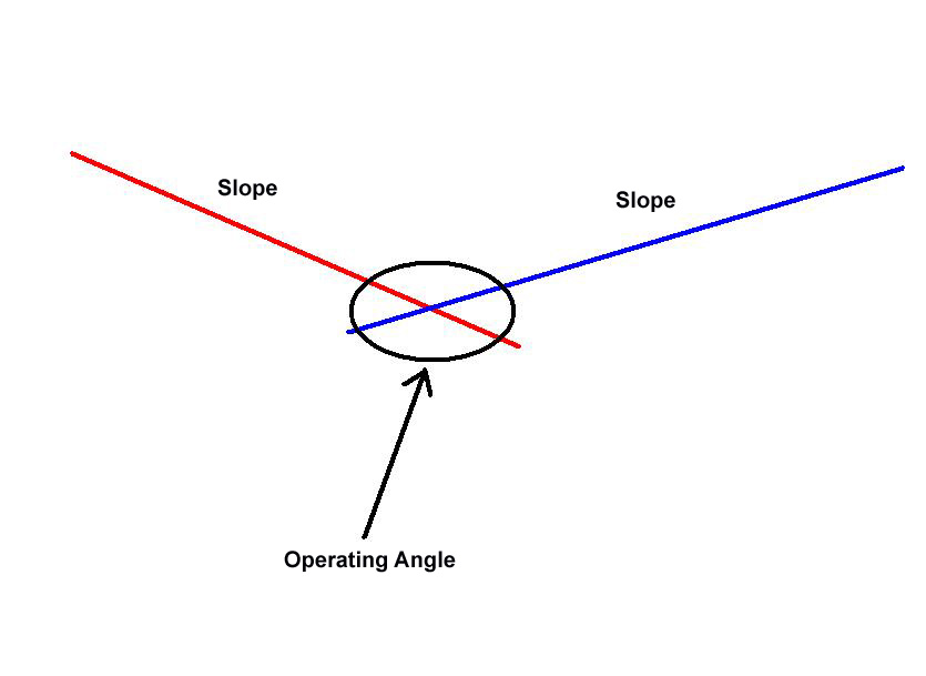 |
Angle:An angle is the measurement of angularity, in degrees, between any two planes. Where those 2 planes meet, they form an angle. In other words, where two lines intersect, providing they are not parallel, there is an angle. In the case of driveshaft tech, where something rotates through that angle, we call it an "operating angle" Slope:Slope. A slope is a special kind of angle. It is the angle formed between the horizontal surface of the earth (one plane), and the object in question (e.g. driveshaft) (second plane). |
|||||||||||||||||||||||||||||||||||||||||||||
When talking about driveshafts, we say that a slope is down if, when viewed from the side of the vehicle, it is higher at the transfer case and lower at the axle (i.e. it descends from the center to the rear of the vehicle for a rear driveshaft or descends from the center to the front of the vehicle for a front driveshaft). The slope is up if, when viewed from the side of the vehicle, it is lower at the transfer case and higher at the axle (i.e. it rises from the center to the rear of the vehicle for a rear driveshaft or rises from the center to the front of the vehicle for a front driveshaft). Phase:We say that 2 U-joints are in-phase if they are fitted to yokes that are fixed on the same shaft, such that the 2 opposing bearing caps in the U-joint that are held captive by the yoke on the shaft (the inboard yoke's U-joint caps) are both in the same orientation. |
||||||||||||||||||||||||||||||||||||||||||||||
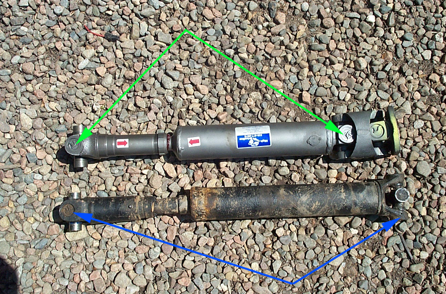 |
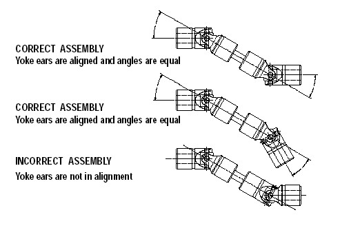
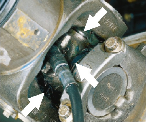
A pic is worth a thousand words. Look at the pic to the left. In the top shaft, the 2 joints indicated by the green arrows (ignore the fact that the right-most is part of a double cardan CV assembly) are in-phase because in both joints, the bearing caps held captive in the shaft are both vertical, while the bearing caps that are free (not held captive in the shaft) are both horizontal. If you then look at the bottom shaft, you will notice that this is not the case with the joints indicated by the blue arrows. The left has captive bearing caps vertically oriented, while the right most joint has it's captive bearing caps oriented horizontally. The joints are therefore 90° out of phase. | |||||||||||||||||||||||||||||||||||||||||||||
Note that this means that they would be in phase if you rotated one or the other 90° (by cutting and re-welding the shaft). Note also that 90° is the most they can ever be out of phase, for as you pass through 90° difference between the two joints orientation, you begin to come back into phase. U-joint life span. |
||||||||||||||||||||||||||||||||||||||||||||||
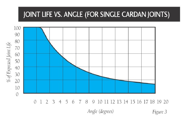 |
One geometry factor that is common to all shafts, regardless of type, is the decrease in U-joint life span that is experienced with an increase in the operating angle of that U-joint. No matter what the shaft style, the greater the angle a U-joint operates at, the shorter it's life span will be. The graph at the left comes directly from Spicer, and shows the range from 100% expected life span at 0° up to just over 15% expected life span at 20°. |
|||||||||||||||||||||||||||||||||||||||||||||
As we learned in part 1, there are 2 types of driveshaft that interest us, each with their own separate geometry requirements. Single-Cardan-style universal joint driveshaft geometry |
||||||||||||||||||||||||||||||||||||||||||||||
 |
The single-cardan style driveshaft, also called a "standard" driveshaft, consists of a tubular shaft with 2 tube yokes, one at each end, that each utilize a single cardan U-joint. Recall how, when we have a single U-joint operating at an angle (as will certainly be the case in any 4x4 because the transfer case output will be above the pinion) it causes the driveshaft to speed up twice and slow down twice each revolution. Uncorrected, this change in angular velocity will cause annoying vibration, wear out U-joints, and cause undue stress and strain on the driveshaft itself, transfer case output, and axle pinion. | |||||||||||||||||||||||||||||||||||||||||||||
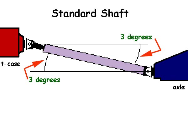 |
The solution is simple and elegant. If we ensure that the U-joints at each end of the shaft are both "in phase" and operating through exactly the same angle, the pinion end of the driveshaft will speed-up and slow down opposite to the transfer case end, and therefore the different angular velocities cancel one another out, the pinion is driven at a steady rate, and vibration is minimal (if I did a decent job of describing why the elliptical paths happen in the first place - you should be able to prove this to yourself). This works fairly well up to angles approaching the maximum operating angles of the U-joints in question. As the angles grow, so do the magnitude of the accelerations and decelerations, and the less effective the matched angle are at eliminating vibration. | |||||||||||||||||||||||||||||||||||||||||||||
| In other words, eventually, you may have a driveshaft operating at such an angle that, even though the input (transfer case) and output (pinion) operating angles match exactly, the shaft will still vibrate. At this point, it's time for a double cardan CV driveshaft! | ||||||||||||||||||||||||||||||||||||||||||||||
 |
Note that in the standard single-cardan shaft "match the angles" geometry the angles do not have to be the same "sign". THIS IS A COMMON MISCONCEPTION. Certainly, the most common method of achieving proper single-cardan shaft geometry is to set the transfer case output and pinion shaft centerlines parallel, thus achieving equal angles between each end of the driveshaft (pic at left). | |||||||||||||||||||||||||||||||||||||||||||||
| Normally, this is done by rotating the axle housing (with shims in a leaf-spring suspension, or with relative lengths of upper and lower control arms with a link suspension). This is because the transfer case output is usually considered pretty fixed - the only way to adjust it is to either lower the transfer case (an all around bad idea and bad deal - I speak from experience) or to tilt the engine up (raise the engine mounts) again - not a good idea). | ||||||||||||||||||||||||||||||||||||||||||||||
 |
However - this is not the only acceptable method of achieving the proper matched-angle geometry. The angle between the driveshaft and pinion can be opposite to the angle between the transfer case and driveshaft - as long as they are equal. Note that they must still be in phase. This unusual configuration is called "Broken back" or "W" geometry (see pic at left ), and is common on agricultural equipment, marine drives, some tractor-trailers that use stub-shafts between front and rear of a tandem assembly, and most often on power-takeoffs like hydraulic pumps and PTO shafts. | |||||||||||||||||||||||||||||||||||||||||||||
Most of the equipment that uses driven shafts in a broken-back configuration though, are fairly low RPM (but not all). The reason is, due to the nature (geometry) of the configuration (again, have a look at the picture above) with this setup, there's a lot more inherent strain on the slip member as it rotates. because of the opposite angles, the shaft "wobbles" the slip member back and forth as it rotates - like a skipping rope being swung. At high rpm, with anything but the tightest slip-joint assembly, this would cause a horrible vibration - that's why Spicer light duty driveshafts do not normally come factory in this arrangement. Note however, that some Land Rovers do have stock driveshafts in the broken back configuration, so it can work! I don't have any experience with these Rover's, but I imagine that the angles in the stock configuration are pretty darned small. As with the more standard single-cardan setup - start increasing the operating angles of the U-joints and the elliptical paths get more and more elliptical, the angular velocities (amount the shaft speeds up and slows down each revolution) get greater, and when you spin that shaft at 1000rpm, the more likely it is that the shaft will be noisy, harsh, and vibrate - EVEN IF the angles are matched. Again...time for the double cardan CV shaft! Double cardan (near) constant velocity driveshaft (commonly known as a CV driveshaft) geometry. |
||||||||||||||||||||||||||||||||||||||||||||||
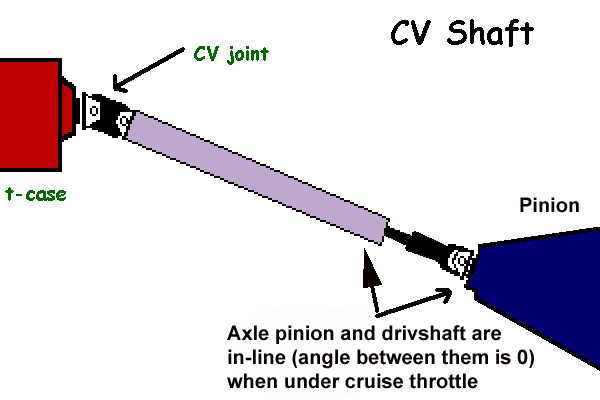 |
Proper CV driveshaft geometry is actually a lot more simple to understand than single-cardan driveshaft geometry. Pictured at left, proper CV shaft geometry is achieved when the operating angle of the CV joint (head assembly) is less than the maximum (and there is some room for increase in operating angle under suspension droop), and the operating angle between driveshaft and pinion is 0 under cruise throttle. | |||||||||||||||||||||||||||||||||||||||||||||
 |
This is because of the clever design of the CV joint, or head assembly. If you refer back to the picture of the CV shaft components in pat one, you will see that the CV head assembly (double cardan joint) contains two cardan style universal joints and a centering yoke assembly. This clever arrangement serves to neutralize the effects of the increasing and decreasing angular velocities, right at the head assembly. This relieves us of having to arrange the pinion yoke operating angle to be equal to the transfer case operating angle. Instead, the pinion is arranged so that the operating angle between it and the driveshaft is zero degrees (0°). | |||||||||||||||||||||||||||||||||||||||||||||
Measuring and calculating universal joint and driveshaft operating anglesSo, we know what the geometry is supposed to be - how do we find out what ours actually is, and what do we do about it? This section discusses measuring your geometry, calculating the results, interpreting the results, and making necessary adjustments. The first 2 steps, measuring slopes of components, and calculating operating angles are the same, regardless of whether you have a standard single-cardan shaft or a double-cardan CV shaft. The third step, interpreting the results, will differ, depending on the style of driveshaft. Before attempting to measure angles ensure that tire air pressure is correct, that the vehicle is at the correct trim (chassis) height (i.e. suspension loaded, operating weight in/on the vehicle, etc.) and the ground surface is perfectly level. The driveshaft also needs to be installed and torqued to spec. Step 1 - Find the slopes of the components involved.Recall that the slope is the angle formed between the component in question, and the horizontal. To find these slopes, we measure them with a protractor as follows: |
||||||||||||||||||||||||||||||||||||||||||||||
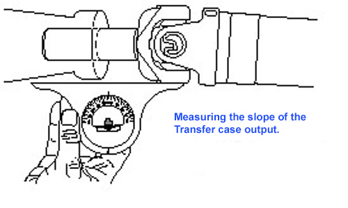 |
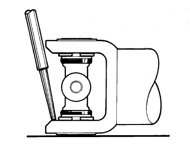
Transfer case Measure the slope of the transfer case output yoke by placing the protractor or angle finder (inclinometer) on the bottom of the bearing cup, (see pic at left). Position the angle finder on the clean flat surface of the bearing cup, level the bubble (if equipped) and note the reading. |
|||||||||||||||||||||||||||||||||||||||||||||
If your transfer case has an output flange, the best way to measure the slope is to temporarily remove the shaft from the flange,place the angle finder against the flat machined surface of the flange, then add or subtract 90° from the reading taken. Remember to re-attach the driveshaft so that you can correctly measure its slope. Remember that the slope is "down" if it is higher at the t case than at the axle. |
||||||||||||||||||||||||||||||||||||||||||||||
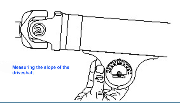 |
Driveshaft Measure the drive shaft slope, as shown, by placing the angle finder directly against the tube. level the bubble (if equipped) and note the reading. Remember that the slope is "down" if it is higher at the t case end than at the axle end. |
|||||||||||||||||||||||||||||||||||||||||||||
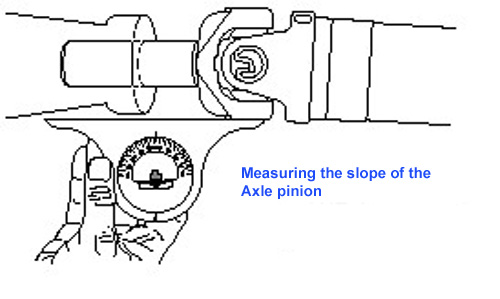 |
Axle Pinion Measure the slope of the pinion yoke by placing the protractor or angle finder (inclinometer) on the bottom of the bearing cup, (see pic at left). Position the angle finder on the clean flat surface of the bearing cup, level the bubble (if equipped) and note the reading. Alternatively, the angle finder can be placed against a flat machined surface that lies 90° to the pinion shaft centerline, the reading taken, and then 90° added to or subtracted from the result. |
|||||||||||||||||||||||||||||||||||||||||||||
Remember that the slope is "down" if it is higher towards the center of the vehicle, and lower at the end of the vehicle. Step 2 - Find each operating angle between each pair of slopes as follows: |
||||||||||||||||||||||||||||||||||||||||||||||
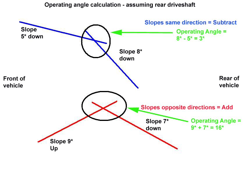 |
If both slopes are in the same direction (up or down), subtract the lesser number from the greater to obtain the operating angle. If both slopes are in different directions (one up and one down), add the lesser number to the greater to obtain the operating angle. |
|||||||||||||||||||||||||||||||||||||||||||||
In the special case of calculating the operating angle at the pinion in a CV shaft application, assign the pinion slope a (+) sign if it is DOWN and a (-) sign if it is UP, then always subtract the pinion slope from the driveshaft slope, regardless of their relative sizes, and make note of the resulting sign (+ or -), as this will help in deciding any possible corrective action. Step 3 - Interpret the resultsAssuming a fairly standard 4x4 setup with no pillow blocks or intermediate shafts, once you have measured all the slopes of the components, and calculated all the operating angles, you should have a piece of paper that has 3 slopes and 2 operating angles written on it. It helps to have a sketch too, like those shown below on the left. Standard (single cardan) Shaft:The first operating angle must be less than the maximum operating angle of the series of U-joint used, and preferably less than half the maximum (remember - you need to allow for increase in operating angles while off road due to suspension movement, and also how the higher the operating angles, the more likely vibration, even if geometry is correct). If it is not, you have only 2 choices: lower the suspension or drop the drivetrain (lower t-case); or switch to a CV style shaft. The second operating angle should be within 0.5° (1/2)° of the first AT CRUISE THROTTLE. This is a critical point. virtually every axle (to a greater or lesser degree, depending on power and suspension) will experience some "axle wrap" or pinion rotation ( pinion rotates up in rear axle, and down in front axle) depending on acceleration and to some extent braking torque. This will of course alter the geometry of the pinion, and therefore the whole driveshaft! Since the driveshaft will presumably spend most of it's time (and therefore the effects of it's vibrations will be most annoying and damaging) in a cruise throttle condition, it is standard practice to set driveshaft geometry for this state (If you have a highly specialized vehicle, like a drag car, this may not apply - and you will want to discuss your needs with an expert like Jess at High Angle Driveline). Generally, for most truck rear axles, at cruise, the pinion will rotate up 1-2° from its static position. As such, it is common practice to shim the axle or adjust the links, rotating the pinion and changing the pinion slope at rests, such that the pinion slope is 2° lower than that required to achieve equal operating angles at rest. Read that bit again, carefully! It's a bit of a juggle, because as you adjust the pinion slope itself, so you also actually alter the driveshafts slope, and therefore the transfer case operating angle as well. Once you get close though, you will easily end up at the correct balance point. the point I'm making is, don't just make a whopping 20° change to the pinion angle, then weld those spring perches on and call it done. That big of a change will have effected things, so you'd have to measure and re-calc all the slopes and operating angles again, as you hone in on the final setting. |
||||||||||||||||||||||||||||||||||||||||||||||
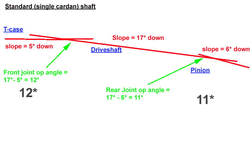 |
Example: Looking at the sample worksheet to the left, and assuming it is for a rear driveshaft |
|||||||||||||||||||||||||||||||||||||||||||||
We can see that the front operating angle is 12°. Assuming we are using a 1350 series U-joint, and the vehicle is not a frequent, long-range freeway cruiser, nor does it have a super-flexy suspension with monstrous travel, we decide that this is satisfactory. The axle joint operating angle is 11°. Because it is a rear driveshaft, the rear pinion will rotate up, let's say 2° under cruise throttle. Since our measurements and calculations were done at static, this means that in reality, under cruise throttle, the pinion slope would change from 6° down to 8° down (even though the pinion wraps "up" - remember we describe slopes as up or down depending on orientation between t-case and axle). This would make the axle joint operating angle actually 17° - 8° = 9° at cruise. Since we need it to equal 12° at cruise, we need to rotate/shim the pinion at rest down 3°. This will result in a static pinion slope of 3°. the would net a cruise throttle pinion slope of 3° + 2° = 5°. That would make our axle joint operating angle now 17° - 5° = 12° - A perfect match for the front! Of course - we would need to make this adjustment (rotate pinion down 3° at rest) and then re-measure and re-calc everything to get it perfect, as the change may effect driveshaft slope and therefore t-case joint angle too. However, this is unlikely with the magnitude of the changes in this example. Double cardan CV shaftThe first operating angle, the CV joint op angle, must be less than the maximum operating angle of CV joint used. Remember - you need to allow for increase in operating angles while off road due to suspension movement. How much you must allow will depend entirely on your suspension design and the terrain driven. If it is not, you have only 2 choices: lower the suspension or drop the drivetrain (lower t-case); or switch to a higher angle capable CV joint shaft. The second operating angle, the pinion op angle, should be within 0.5° (1/2)° of zero (0°) AT CRUISE THROTTLE. This is a critical point. virtually every axle (to a greater or lesser degree, depending on power and suspension) will experience some "axle wrap" or pinion rotation ( pinion rotates up in rear axle, and down in front axle) depending on acceleration and to some extent braking torque. This will of course alter the geometry of the pinion, and therefore the whole driveshaft! Since the driveshaft will presumably spend most of it's time (and therefore the effects of it's vibrations will be most annoying and damaging) in a cruise throttle condition, it is standard practice to set driveshaft geometry for this state Generally, for most cars and trucks rear axles, at cruise, the pinion will rotate up 1-2° from its static position. As such, it is common practice to shim the axle or adjust the links, rotating the pinion and changing the pinion slope at rests, such that the pinion slope is 2° lower than that required to achieve an operating angles of zero at rest. Read that bit again, carefully! It's a bit of a juggle, because as you adjust the pinion slope itself, so you also actually alter the driveshafts slope, which directly affects what your pinion angle must be, in a feedback type loop. Once you get close though, you will easily end up at the correct balance point. The point I'm making is, don't just make a whopping 20° change to the pinion angle, then weld those spring perches on and call it done. That big of a change will have effected things, so you'd have to measure and re-calc all the slopes and op angles again, as you hone in on the final setting. |
||||||||||||||||||||||||||||||||||||||||||||||
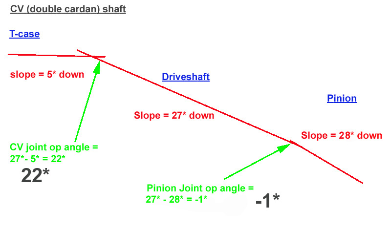 |
Example: Looking at the sample worksheet to the left, and assuming it is for a rear driveshaft |
|||||||||||||||||||||||||||||||||||||||||||||
We can see that the front CV operating angle is 22°. Assuming we are using a High Angle 1350 series CV shaft, we are comfortably within the proper operating spectrum here. The axle pinion joint operating angle is -1°. Because it is a rear driveshaft, the rear pinion will rotate up, let's say 2° under cruise throttle. Since our measurements and calculations were done at static, this means that in reality, under cruise throttle, the pinion slope would change from 28° down to 30° down (even though the pinion wraps "up" - remember we describe slopes as up or down depending on orientation between t-case and axle). This would make the axle joint operating angle actually 27° - 30° = -3° at cruise. Since we need it to equal 0° at cruise, we need to rotate/shim the pinion at rest down 3°. This will result in a static pinion slope of 25°. This would net a cruise throttle pinion slope of 25° + 2° = 27°. That would make our cruise throttle axle joint operating angle now 27° - 27° = 0° - A perfect setup for a CV shaft! Note that, in the case of a CV shaft, since we always calculate the angle the same way driveshaft slope minus pinion slope, the sign of the result tells allows us to write an equation, the result of which tells us whether we need to rotate the pinion at rest down or up. The equation is RR=DS-PS-WA. Where RR = rotation required (of the pinion at rest), DS - driveshaft slope, PS = pinion slope, and WA is the estimated pinion wrap angle. If the result is (-), we must rotate the pinion down at rest that many degrees, if the result is (+) we must rotate the pinion up that many degrees. Of course - we would need to make this adjustment (rotate pinion down 3° at rest) and then re-measure and re-calc everything to get to perfect, as the change may effect driveshaft slope. However, this is unlikely with the magnitude of the changes in this example. How to chose a Driveshaft for your Rig.This is actually a fairly easy one to answer. First - buy the absolute best you can possibly afford. Why? It is almost impossible to overstate the massive annoyance of a bad driveshaft. Driveshaft vibration is horrendously annoying - street queen or trail-only rig. Believe me, I know. My current buggy, the Wolf, is always trailered, and spends 90% of it's time below 10mph - occasionally it may get to 40mph. I had NO IDEA how bad my cobbled-together shaft was until I replaced it with a High Angle driveshaft. Even at slow speeds, a crappy driveshaft will EASILY suck the fun out of driving your rig. I figured - it's trail buggy - it's loose and noisy anyway - who cares. Well, I learned....it is Sooooooooo much nicer with a decent balanced shaft, operating within it's angle capabilities - and of course - the peace of mind for the components that actually put the power to the axles is priceless. Do you need a a CV shaft, or will a standard single-cardan style do? Well, in my opinion, unless your rig is only an inch or 2 over stock suspension height, with minimal wheel travel / flex, the answer is definitely YES! The CV driveshaft offers several HUGE advantages to the off-road vehicle. First, the pinion and pinion yoke can be rotated up out of harms way, where it will be less susceptible to damage from rocks and other obstacles. Secondly, the only limit to our operating angle at the CV joint (and thus how much suspension height we can run) is the limit of the double-cardan joint itself. A stock Spicer double cardan CV joint can run successfully at about 22°, and a High Angle Driveline double-cardan CV joint can be run successfully at as much as 32° !!! This allows for successful driveshaft installations in vehicles with much more suspension height than a simple single-cardan shaft can accommodate. Even if you matched the angles on a single cardan shaft exactly, you could never run it safely and vibration free at 30°! Thirdly, the double-cardan CV joint assembly is simply better and more efficient at reducing or eliminating driveshaft vibration. Even at smaller angles, and even with correct matched-angle geometry, the single-cardan shaft is still susceptible to vibration. The CV shaft will always run smoother, quieter, and with less stress on the U-joints, and transfer case and pinion shafts, bearings, and seals. The only advantage the single-cardan shaft has is that it is cheaper to manufacture / buy, and you don't have to buy a centering yoke or a third U-joint when rebuilding it. As always - the best costs a little more! Part 3 - Driveshaft maintenance.Driveshafts should be carefully inspected and lubricated (as applicable - some components, and even some entire driveshafts are non-serviceable and cannot be re-greased) at recommended original equipment vehicle manufacturers’ service intervals and/or at Spicer recommended lubrication intervals OR you can use my recommendations, which are: Severe use (wet, muddy, or high-torque carrying use, extreme low gears (80:1 and lower), large tires(35" and over)) 3000 miles, 2 months, or 250 Hrs, whichever comes first Moderate use (dry conditions, on and off road use) 5000 miles, 3 months, 500 Hrs, whichever comes first Mild use (mostly street duty - some off-road) 8000 miles, 6 months, whichever comes first Before undertaking any of these procedure, be sure to read and heed the section on Safety. Driveshaft SafetyCAUTION Caution – Under
no circumstances should individuals attempt to perform driveline
service and/or maintenance procedures for which they have not been
trained or do not have the proper tools and equipment. See warning
below. WARNING WARNING WARNING 1. ALWAYS wear safety
glasses when performing maintenance or service. Failure to wear
safety glasses can result in personal injury and/or partial or complete
vision loss. Note – For driveshaft applications that have pillow blocks, dampers, parking brakes or retarders, refer to these component manufacturers’ or the original equipment vehicle manufacturers’ service manuals for proper procedures. Inspection Note – The following
procedures are to be performed prior to any lubrication of universal
joints or slip members. Note - The following pics are taken from Spicer's Heavy Duty Driveshaft manual (trucks over 30,000lbs) so the driveshafts themselves will appear huge, compared to what we 4x4 users are used to. To properly inspect the driveshaft, you need to block the vehicles wheels, set the parking brake, put the transmission in Neutral (N), and the transfer case in 2wd. If you have a selectable locker or lockout manual hubs, unlock them. This is all important because you want to make sure that there is no drag or pressure or bind on the driveshaft that can mask wear and sloppiness during your inspection. INSPECTING END FITTINGSVisually inspect all input and output end-fitting (yoke) retaining nuts, clips, or bolts for any gaps between mating surfaces. If gaps are present, consult transmission, axle or transfer case original equipment manufacturers’ service and maintenance manuals for proper fastener specifications. |
||||||||||||||||||||||||||||||||||||||||||||||
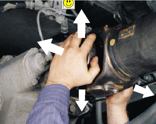 |
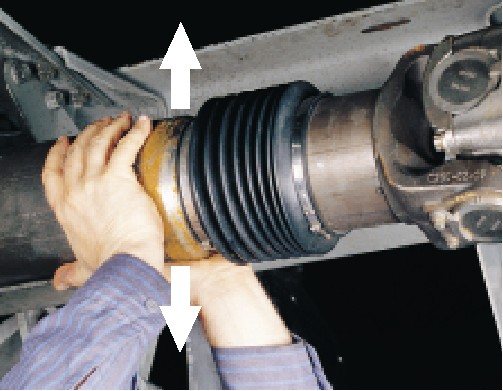
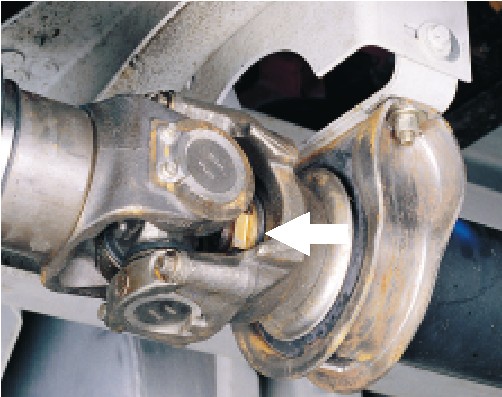
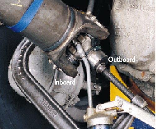
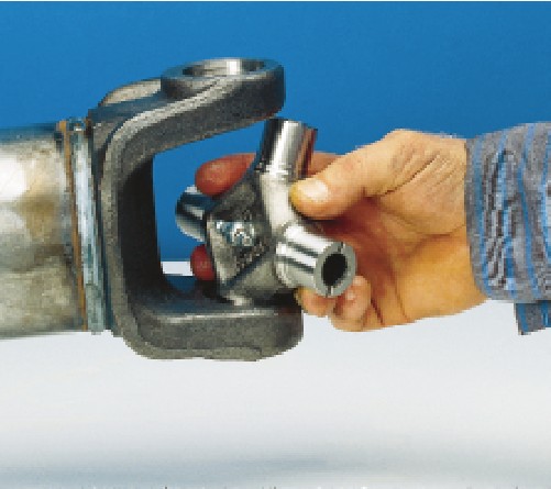
Check all input and output end fittings (yokes at each end of driveshaft) for looseness or play. Take hold of the end fitting with both hands. Try to move it vertically and horizontally to feel any looseness. (See photo left.) Listen for any clicking, or grinding noise from the joint. There should NOT be any movement in the end fittings. If looseness is evident, U-joints or yokes will have to be replaced. | |||||||||||||||||||||||||||||||||||||||||||||
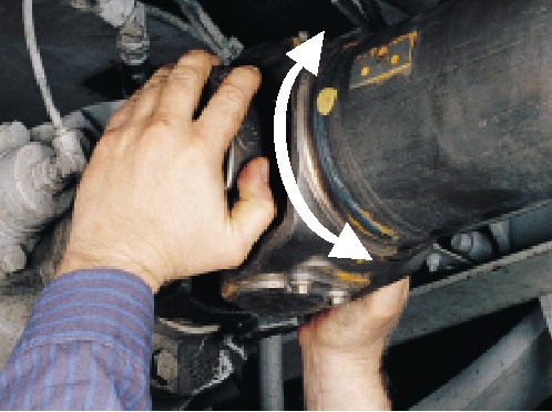 |
If the end fittings are tight, check for excessive radial looseness of the transfer case output shaft and axle input shaft (pinion) splines relative to the end fitting. Take hold of the end fitting with both hands, rotate left to right, feeling for play or backlash (see photo left.) Listen for any clicking, or grinding noise from the joint. If radial looseness is evident, U-joints or yokes will have to be replaced. | |||||||||||||||||||||||||||||||||||||||||||||
| Visually inspect for damaged bearing retainers or stamped straps, loose bearing retainer bolts or strap bolts, loose companion flange bolts and nuts, loose or missing spring tabs or spring tab bolts, damaged tangs on end fittings, damaged or missing snap rings, and rotating bearing cups. If any of these situations are evident, replacement of the components is necessary. | ||||||||||||||||||||||||||||||||||||||||||||||
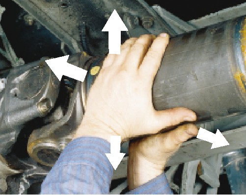 |
Check for excessive looseness across the ends of the universal joint bearing cup assemblies and trunnions. Take hold of the inboard yoke on the driveshaft with both hands. Try to move yoke vertically and horizontally. (See photo left above.) There should be less than .006 in. (.15mm) movement in the universal joint kit relative to the inboard or outboard yokes. If looseness is greater than .006 in. (.15mm), the universal joint kit must be replaced. | |||||||||||||||||||||||||||||||||||||||||||||
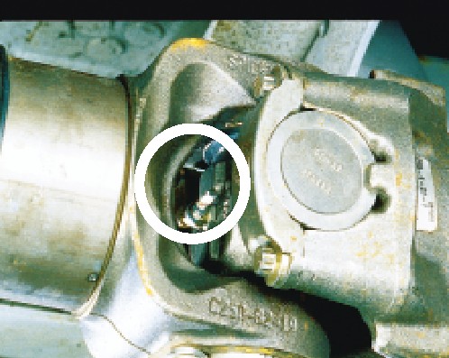
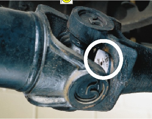
INSPECTING UNIVERSAL JOINTSVisually inspect all universal joint kits in the driveshaft assembly. Make a careful inspection of the caps of the U-joints where they are held captive in the end fittings (yokes). Look to see if the caps are polished or shiny. If they are, it indicates that the cap is spinning in the bore, and the U-joint and attachment hardware will have to be replaced. There are 3 types of U-joints used in driveshafts:
Each requires slightly different inspection procedures |
||||||||||||||||||||||||||||||||||||||||||||||
 |
Relubable style Check for the presence of all grease zerk (nipple) fittings. (See photo left). Grease zerk (nipple) fittings should not be missing, loose or fractured. If grease zerk fitting is loose, tighten to required specifications. If grease zerk fitting is fractured, replace grease zerk fitting and tighten to required specifications. If grease zerk fitting is missing, the entire universal joint kit needs to be replaced. |
|||||||||||||||||||||||||||||||||||||||||||||
 |
Permanently Lubricated Plug Style Permanently lubricated plug style universal joint kits do not contain grease zerk fittings, only a plug. (See photo left) Make sure plug is not missing, loose or fractured. If the plug is loose, tighten to required specifications. If a plug is missing or fractured, the entire universal joint kit needs to be replaced. |
|||||||||||||||||||||||||||||||||||||||||||||
 |
Permanently Lubricated Net-Formed Style Net-formed universal joints do not contain grease zerk (nipple) fittings or plugs and are not relubable (See photo left) |
|||||||||||||||||||||||||||||||||||||||||||||
INSPECTING SLIP MEMBERS |
||||||||||||||||||||||||||||||||||||||||||||||
 |
Check the slip member assembly for excessive radial looseness. Using a dial indicator (or a very carefully calibrated eyeball :-), take hold of the tubing near the slip member with both hands and try to move vertically, up and down relative to the ground. There should be limited looseness in the slip member assembly. (See photo left) If looseness is greater than .012 in. (.30mm) as read on dial indicator, replacement of the slip member assembly is necessary. | |||||||||||||||||||||||||||||||||||||||||||||
 |
For an inboard and outboard slip yoke assembly design, check to be sure the slip yoke welch plug is not loose, missing or damaged. (See photo left) If any of these situations are evident, replacement of the slip yoke and professional re balancing of the driveshaft is necessary. | |||||||||||||||||||||||||||||||||||||||||||||
 |
Visually inspect for
the presence of the grease zerk fitting, if applicable, on the slip
yoke. (See photo left) Grease zerk fittings should not be missing,
loose or fractured. If grease zerk fitting is loose, tighten to
required specifications. If grease zerk fitting is missing or fractured,
the slip members may need to be replaced. Be sure to follow above
procedure for inspection of radial looseness in slip member assembly. If slip member assembly is within acceptable limits as stated above install new grease zerk fitting and tighten to required specifications. Be sure to completely re lubricate slip member assembly with recommended lubricant. |
|||||||||||||||||||||||||||||||||||||||||||||
 |
Check the slip yoke seal. (See photo left) Make sure the seal is properly attached to the slip yoke and is not loose or damaged. If any of these situations are evident, replacement of slip member assembly is necessary. | |||||||||||||||||||||||||||||||||||||||||||||
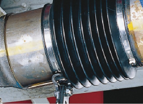 |
For permanently lubricated slip members, check yoke shaft boot (see photo left) or seal can. Make sure the boot or seal can is properly attached to the yoke shaft and tube sleeve and no damage or looseness is apparent. Visually inspect boot for tears. Inspect boot or seal can for punctures. Inspect boot clamps for damage. If any of these situations are evident, replacement of slip member assembly is necessary. | |||||||||||||||||||||||||||||||||||||||||||||
INSPECTING TUBINGCheck the driveshaft for bent or dented tubing, cracks, or failed welds. If any of these situations is evident, replacement of the complete driveshaft assembly or tube is necessary. INSPECTING CENTER BEARINGS |
||||||||||||||||||||||||||||||||||||||||||||||
 |
Visually inspect all center bearings, end-fitting midship nuts for any gaps between the mating surfaces. (See photo left) Be sure to repeat check for broken back and backlash.for all center bearing end fittings. | |||||||||||||||||||||||||||||||||||||||||||||
 |
Inspect the center bearing
bracket bolts for looseness. (See photo left) If looseness is evident,
re tighten center bearing bracket bolts. Consult the vehicle manufacturers’
specifications for proper bolt torque. Check the alignment of the
bracket before tightening the bolts. Bracket should not be skewed.
Visually inspect the center bearing rubber cushion for damage. Make sure the slingers are not rubbing against the rubber cushion. Verify that the rubber cushion is properly seated in the metal bracket. If any of these situations are evident, replacement of the center bearing assembly is necessary. |
|||||||||||||||||||||||||||||||||||||||||||||
LubricationWhy?Lack of proper lubrication is one of the most common causes of universal joint and slip member problems. In all of my experience, (and Jess will back me up on this too) the U-joints most likely to fail are the re greasable kind that haven't been properly lubricated frequently enough. Proper re lubrication flushes the universal joints, thus removing abrasive contaminants from the bearings. Relubable slip members must also be adequately re lubricated to prevent slip member failure. When?First, on installation, regardless of if the joint is re lubable or not. Replacement universal joint kits contain only enough grease to provide needle roller bearing protection during storage. It is therefore necessary to completely lubricate each replacement kit prior to assembly into the yokes. After initial installation, you can follow either your vehicle manufacturer's recommended intervals, Jess's recommendations, or follow my recommendations, which are: Severe use (wet, muddy, or high-torque carrying use, extreme low gears (80:1 and lower), large tires(35" and over)) After every off-road trip, 3000 miles, 2 months, or 250 Hrs, whichever comes first Moderate use (dry conditions, on and off road use) 5000 miles, 3 months, 500 Hrs, whichever comes first Mild use (mostly street duty - some off-road) 8000 miles, 6 months, whichever comes first How?
|
||||||||||||||||||||||||||||||||||||||||||||||
 |
Using the recommended lubricant (see below) use a hand operated grease gun (air powered guns use to much pressure and can blow out seals and force contaminant in) and pump grease into the grease nipple until it flows out from all 4 bearing cap seals. You cannot over-grease a U-joint. | |||||||||||||||||||||||||||||||||||||||||||||
Note: If your shaft uses permanently sealed (non re lubable U-joints - don't attempt to disassemble them to re-lube them, and DO NOT attempt to use any of those sharp needle attachments designed for piercing seals to inject grease. You will only make things worse, and hasten their demise, as you will ruin the seals. Just leave them in there, and replace the whole thing when it wears out. If you find yourself dissatisfied with their life-span, consider trying the re lubable kind in future.
|
||||||||||||||||||||||||||||||||||||||||||||||
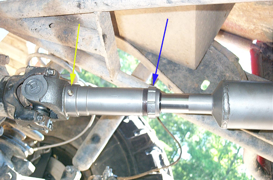 |
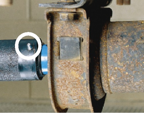
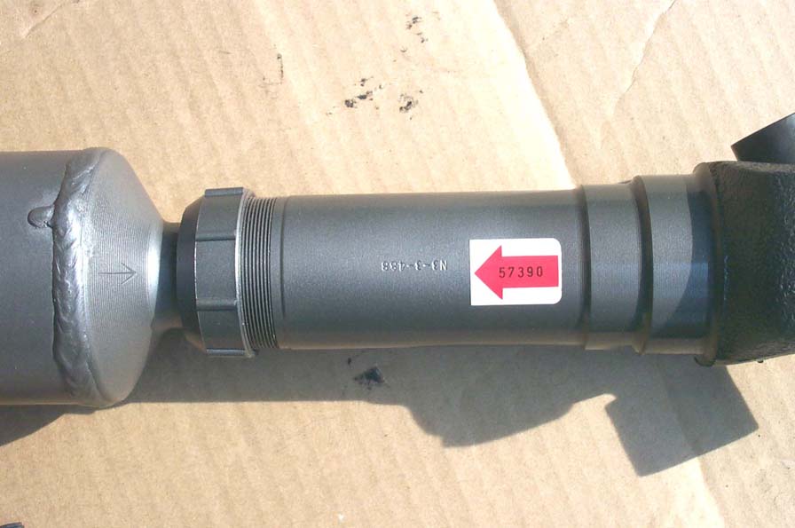
Remove one end of the driveshafts connection so that you can fully compress the slip member (splines all the way in). If your driveshaft has the grease nipple in the dust cap (blue arrow) - pump grease till it flows out relief hole. | |||||||||||||||||||||||||||||||||||||||||||||
|
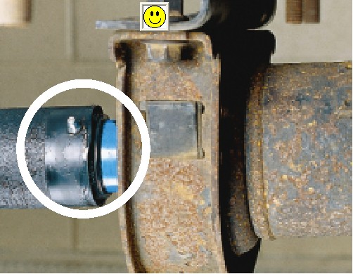
If your driveshaft slip member has the grease nipple at the yoke end (like mine - yellow arrow in pic above) - cover relief hole (pic at left) and pump grease till it flows from under the dust cap (blue arrow in pic above). | |||||||||||||||||||||||||||||||||||||||||||||
|
||||||||||||||||||||||||||||||||||||||||||||||
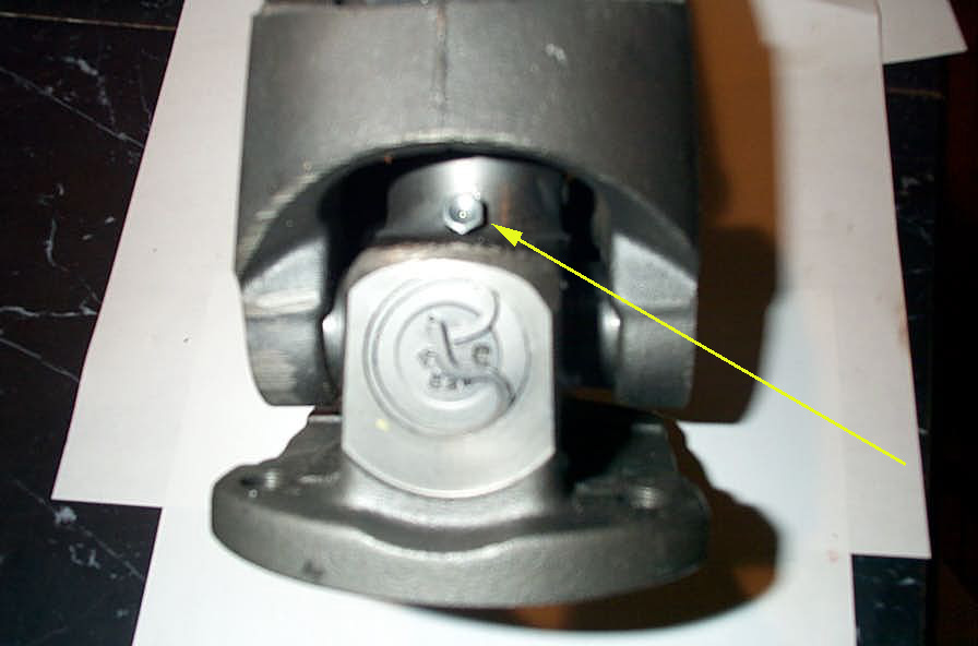 |
Disconnect the CV head assembly from the vehicle so that you can access the recessed grease fitting in the CV assembly (yellow arrow). Using a needle attachment on your grease gun, pump grease into the fitting until it flows out freely. | |||||||||||||||||||||||||||||||||||||||||||||
THIS is critical. This is probably the single most neglected grease fitting on a 4x4. Long, smooth driveshaft operation demands proper and frequent lubrication. You wouldn't be too lazy to change the oil in your engine for 50 000 miles, so don't abuse your driveshaft that way either. Important Note: High Angle Driveline is the ONLY company to offer a true HIGH ANGLE 1350 CV assembly that is re lubable for smooth operation and long-life. the others say it couldn't be done.......but they were WRONG! Jess has worked his magic - and it works, and it still brutally strong - anyone claiming otherwise is fooling themselves. This is reason enough to go to Jess for your driveshafts. Having that CV head assembly wear out prematurely because of improper service and ingress of contaminants (and if you use your 4x4 like I do, you WILL get water and mud and grit and dust in EVERYTHING!) would be a huge pain, and expensive to repair/replace! With What?Spicer recommends that
the following requirements be met for any lubricant that will be
used to service most vehicular, industrial and all auxiliary driveshaft
applications. *National Lubricating Grease Institute GREASE COMPATIBILITY* Did I do it right?Ever wonder if you HAVE to get grease purging from all 4 bearing caps in a U-joint when lubricating it? Ever wonder why? The answer is "yes, you do, because otherwise you cannot be sure all bearings are fully lubricated and all foreign material and water is evacuated due to unequal seal pressures due to tolerance stack up in components." What the heck does that mean? It means, grease the joint until all 4 sealed purge! And if all 4 will not purge - relieve the pressure on the bearing caps that will not, and try again. The procedure is outlined below. If the joint still will not purge from all 4 seals - it must be replaced. See the Spicer Video on Proper U-joint Lubrication for the complete story. Procedure for releasing universal joint bearing seal tensionBearing strap / U-bolt style. |
||||||||||||||||||||||||||||||||||||||||||||||
 |
Utilizing a brass hammer or punch and wearing safety glasses, sharply strike inboard yoke on lug ear once to try to firmly seat bearing cap and relieve tension across span. Rotate shaft 180 degrees and repeat procedure on opposite lug ear. Apply grease gun pressure and purge all four bearings until fresh grease is seen at all four bearing seals. | |||||||||||||||||||||||||||||||||||||||||||||
| If striking lug ears does not cause purging, remove the retaining hardware from the affected bearing caps (follow removal procedure outlined below if required, making sure to mark driveshaft for phasing before removing any hardware) and unseat bearing cup assemblies from yokes (by tapping on yoke or bearing cup with a soft-faced hammer if required). Once the bearing cup assemblies are free, allow the driveshaft to rest on a. support strap. Remove snap rings in lug ears of the inboard bearing caps that are not purging Note – Spicer snap rings can be reused if they ARE NOT severely corroded or distorted. If corroded or distorted, replace used snap rings with new | ||||||||||||||||||||||||||||||||||||||||||||||
 |
Purging Inboard (captive in driveshaft yoke) BearingsApply a c-clamp around the outboard (those that seat in the pinion or T-case yoke) bearings. Apply grease gun pressure. Completely purge both inboard (those captive in the driveshaft yoke) bearings. See pic (purge inboard) Purging Outboard (that connect to yokes) BearingsIf outboard bearings fail to purge, slightly loosen c-clamp and reapply grease gun pressure until both outboard bearings purge. |
|||||||||||||||||||||||||||||||||||||||||||||
After all four bearings purge fresh grease, re-tighten c-clamp to squeeze out excess grease and wipe clean. This will ease installation of universal joint kit back into yoke. Install universal joint in the yoke using new hardware and torque bolts or nuts to the required specifications. If the bearings still will not purge, complete removal and replacement of the universal joint is required. Driveshaft Removal |
||||||||||||||||||||||||||||||||||||||||||||||
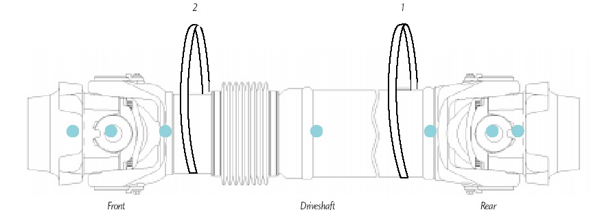 |
Mark Driveshaft (“Phasing
Marks”) It is imperative to mark all the mating components of a driveshaft. Mark the driveshaft with a marking stick, paint marker or other legible marking device. In addition, be sure to mark all bearing positions, spline positions, shaft locations and all bearing retainers. This assures proper reassembly of the driveshaft into the vehicle, in its original position. |
|||||||||||||||||||||||||||||||||||||||||||||
 |
This pic shows the phasing marks on my new shaft. | |||||||||||||||||||||||||||||||||||||||||||||
Support the driveshaft with a support strap, if required, at the appropriate location, Attach support straps to frame rails or some structural part of the vehicle. Remove the bearing retainer bolts and bearing retainers or stamped straps or remove nuts and U-bolts. Stamped straps and stamped strap bolts or bearing retainer bolts CANNOT be reused. Loosening or removing bearing retainer bolts or U-bolts requires replacement of used bolts with new. Do not substitute other hardware – Spicer driveshaft hardware is made from correct alloys and is specially heat treated. |
||||||||||||||||||||||||||||||||||||||||||||||
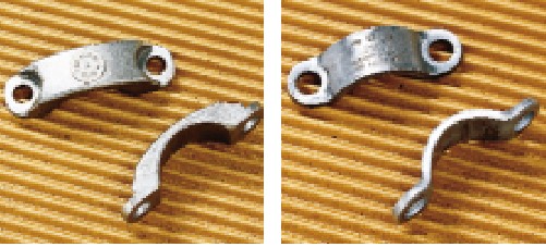 |
Note – New cold formed bearing retainers DO NOT need to be replaced. Replace only if damaged. Pic at left shows cold-formed bearing retainers (that can be re-used) on the left, and stamped straps (that cannot be re-used) on the right. | |||||||||||||||||||||||||||||||||||||||||||||
 |
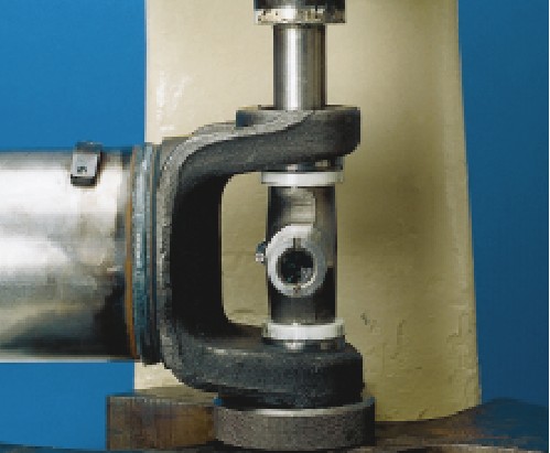
It may be necessary to unseat bearing cup assemblies by tapping on yoke or bearing cup with a soft-faced hammer. (See pic at left.) Once the bearing cup assemblies are free, collapse the driveshaft until both bearing assemblies clear the open end yoke cross holes. Allow the driveshaft to rest on support strap. Once the driveshaft is free, remove the driveshaft from the support straps and take it to a work bench area. Check all end yokes for looseness. Take hold of end yoke with both hands. Try to move it vertically and horizontally to feel any looseness. There should NOT be any looseness in the end yokes relative to the input or output shafts to which they are connected. If looseness is evident, the end yoke needs to be replaced. |
|||||||||||||||||||||||||||||||||||||||||||||
|
Visually inspect all end yoke retaining nuts or bolts for any gaps between mating surfaces. Pic at left shows gap under yoke mounting nut. Inspect all end yoke cross hole surfaces and bolt hole threads for damage. If the bolt hole threads are damaged, the yoke must be replaced. |
|||||||||||||||||||||||||||||||||||||||||||||
Replacing universal joints in the driveshaft.Remove driveshaft from vehicle as described above, and set on work bench Remove joints from shaft |
||||||||||||||||||||||||||||||||||||||||||||||
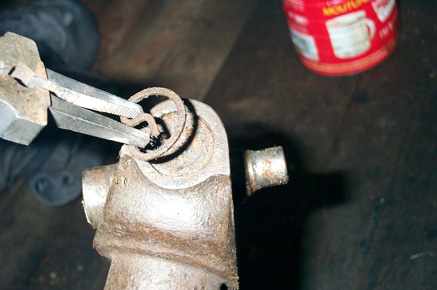 |
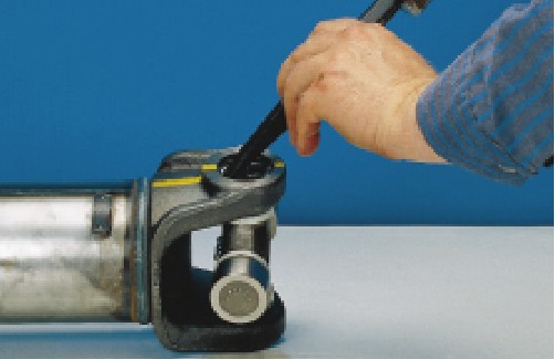
Remove all internal and external snap rings. | |||||||||||||||||||||||||||||||||||||||||||||
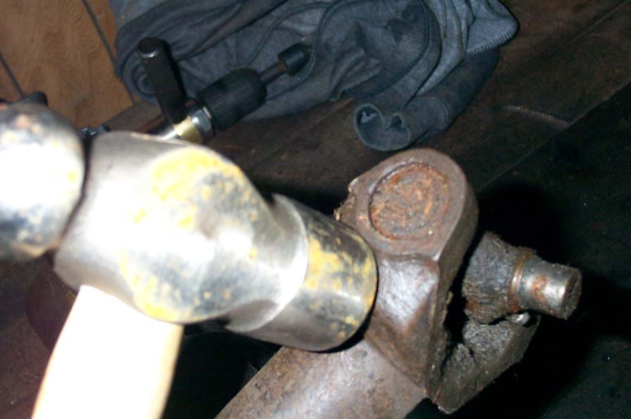 |
Support driveshaft, and with a hammer, strike the shoulder of the yoke. Inertia will cause the bearing cap to walk out of the bore. Grasp the bearing cap with a pair of channel-lok or vice grip pliers, and twist it free from the trunnion Rotate the driveshaft yoke 180° and repeat. Alternatively, you can use a press or hammer and socket to drive the bearing cups from the yoke bores. Whichever method you choose, be sure not to damage the yoke in the process. | |||||||||||||||||||||||||||||||||||||||||||||
 |
Remove U-joint cross from yoke. Thoroughly clean and inspect the bores of the yoke, follow inspection procedures above if required. |
|||||||||||||||||||||||||||||||||||||||||||||
Install new joints in shaftNote – Spicer Life replacement universal joint kit bearing assemblies contain only enough grease to provide needle roller bearing protection during storage. It is therefore necessary to completely lubricate each bearing assembly. It is also necessary to fully lubricate the universal joint kit after it is installed in the vehicle. |
||||||||||||||||||||||||||||||||||||||||||||||
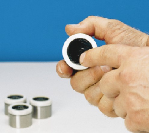 |
Using a high-quality, N.L.G.I., E. P. Grade 2 lubricating grease, wipe each bearing cup assembly with grease. Fill all cavities between the needle rollers. Also apply a liberal coating of grease on the bottom of each bearing cup assembly and on the lip of the seal. DO NOT overfill the bearing cups though, as this will create excessive hydraulic pressure in the bearing caps when the joint is installed, making proper installation extremely difficult. Caution – Spicer DOES NOT recommend wiping the outside of bearing cup assemblies or yoke cross holes with grease, oil or silicone-based sprays. This could result in bearing cup assembly rotation in yokes. |
|||||||||||||||||||||||||||||||||||||||||||||
|
Position the journal cross into the yoke cross holes with the grease zerk (nipple) fitting inward toward tubing. Ensure that the grease zerks at the transfer case and pinion ends of the shaft are both on the same side of the shaft so that they can both be lubricated at the same time without having to rotate the shaft. |
|||||||||||||||||||||||||||||||||||||||||||||
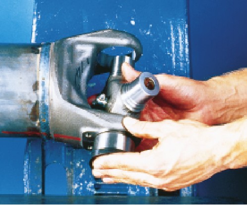 |
Move one end of the journal cross to cause a trunnion to project through the cross hole beyond the outer machined face of the yoke ear. Place the bearing cup assembly over the protruding trunnion diameter and align it to the yoke cross hole. | |||||||||||||||||||||||||||||||||||||||||||||
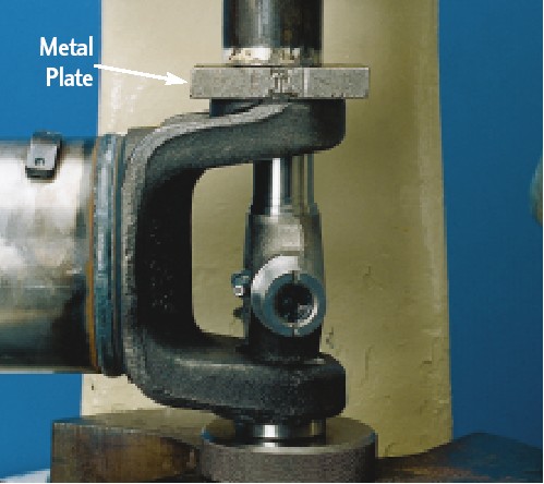 |
Align the yoke in an arbor press with the bearing assembly resting on the base of the press. Cover the yoke ear with a metal plate that has 0.25 inch minimum thickness. Push the yoke onto the bearing cup assembly. |
|||||||||||||||||||||||||||||||||||||||||||||
 |
Turn the yoke over 180° and place a push rod that is smaller than the diameter of the bearing cup assembly onto the bearing cup assembly and continue pressing the bearing cup into the yoke cross hole until far enough to install a snap ring. Flip yoke over 180°, place second bearing cup over the trunnion and align it to the yoke cross hole. Align the yoke in an arbor press with the previously installed bearing assembly resting on a support on the base of the press. Place a push rod that is smaller than the diameter of the bearing cup assembly onto the bearing cup assembly and continue pressing the bearing cup into the yoke cross hole until far enough to install a snap ring. |
|||||||||||||||||||||||||||||||||||||||||||||
 |
Remove yoke from arbor press. Install a snap ring using snap ring pliers. Seat installed snap rings into grooves using a small chisel or punch. (See photo at left). |
|||||||||||||||||||||||||||||||||||||||||||||
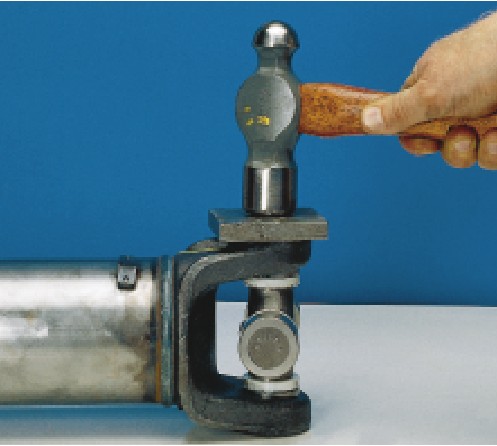 |
Flex the journal cross
to make sure it moves smoothly and freely in the bearings. If the joint is stiff, place a plate on the yoke ear and hit the plate with a hammer to seat the bearing cup assemblies. (See photo at left.) |
|||||||||||||||||||||||||||||||||||||||||||||
 |
Flex the journal cross to make sure it moves smoothly and freely in the bearings. If not, disassemble and inspect the journal and bearing assemblies for skewed or dropped needle rollers. | |||||||||||||||||||||||||||||||||||||||||||||
Driveshaft Installation:Place the driveshaft in place in the vehicle, use supporting straps if required. |
||||||||||||||||||||||||||||||||||||||||||||||
 |
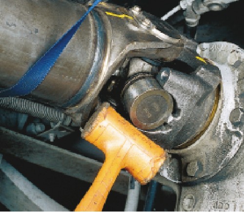
Working from the transfer case end, use a soft-faced hammer to tap the universal joint into the transfer case output end yoke. Make sure to align the universal joint in end yoke, matching up the phasing marks made during removal to ensure original driveshaft orientation. | |||||||||||||||||||||||||||||||||||||||||||||
Install the bearing retainers or new stamped straps and new bolts Torque the bolts down evenly and to required specifications. 1310 and 1330 series joint retention hardware should be tightened to 17 ft/lbs and 1350 joint hardware to 20 ft.lbs. DO NOT over tighten the retention hardware as it will distort the bearing cap and cause the bearings and joint to fail.Check to make sure the bearing cup assemblies are fully seated in the yoke ears. Repeat for the axle pinion yoke. It may be necessary to extend or collapse the slip member assembly to allow clearance to install driveshaft into the axle pinion yoke. Completely re lubricate all the universal joints and the slip member assembly (if slip member assembly is re lubable) as described in the lubrication section Part 4 - U-joint techChoosing U-jointsWhen it comes to universal joints of a given size or series, there are 2 decisions to make - which brand to choose, and which style (permanently sealed or re lubable) The first decision is simple in my opinion. Spicer Life Series no question. I believe they are simply the best. Why? I'll let them explain it (below): Why should you use Spicer U-joints? According to Spicer: Spicer has been the leader in cardan universal joint technology since 1904, when Clarence Spicer patented the first practical application of a universal joint to replace the chain drives of his day. Since that time, we have refined our universal joints with improved forging technology, metallurgical studies, hardening processes and sealing capabilities to ensure greater durability and low maintenance. Spicer engineers research and implement advanced hot and cold metal forming processes for journal crosses, heat treating methods for case hardening bearing cups, finite element analysis and three-dimensional modeling to understand and control stress points, and perform myriad laboratory and application tests to validate joint performance. We sweat the details so all of our cardan joints provide you with longer, trouble-free service. There are 2 different models to choose from - the Spicer Time-Tempered™ and the Spicer Life™. Both are described below. As you will see, the only choice for us is the Spicer Life™ series. Spicer Time-Tempered™ Replacement Cardan Universal Joints* This OE-acceptable replacement U-joint kit has a hot-forged steel journal cross that is heat treated and through drilled for grease channels. It is equipped with a grease fitting for ease of re lubrication. Journal cross trunnions are hardened for long life, and the faces are grooved to ensure consistent lubrication of the needle roller bearings. |
||||||||||||||||||||||||||||||||||||||||||||||
 |
The Spicer Time-Tempered replacement cardan U-joint's distinctive blue rubber seals provide grease retention within the bearing assembly while protecting it from contaminants and are designed to purge grease upon re lubrication. Bearing cups are carbonitrided and uniformly case hardened for higher strength, then machined to a higher tolerance for improved fit and driveshaft balance. This machining process and its resulting higher tolerances add a level of quality, putting this U-joint a step above average over-the-counter replacement kits. *Spicer Time-Tempered universal joint kits should NOT be used in high-performance vehicles, motor sport applications or vehicles frequently used in severe off-road conditions. |
|||||||||||||||||||||||||||||||||||||||||||||
| Spicer Life™ Original Equipment (OE) Cardan Universal Joints | ||||||||||||||||||||||||||||||||||||||||||||||
|
The newest cardan universal joint in the Spicer product line offers advanced design features for longer life and superior performance. Bearing cups are case hardened through a carburizing heat treat process, and the inside diameter and thrust washer surface are machined to the highest tolerances of all Spicer bearing assemblies. The journal cross is cold-formed for added strength, and trunnions are machined to give the best possible surface for the needle roller bearings. | |||||||||||||||||||||||||||||||||||||||||||||
| Spicer Life OE cardan universal joints stand above the rest for the tough, worry-free performance demanded by today's discriminating consumer and are the preferred choice of many automotive design engineers for passenger cars, pickup trucks and sport utility vehicles. They also have proven performance and are used extensively by professional motor sport teams in IROC, NASCAR and NHRA. | ||||||||||||||||||||||||||||||||||||||||||||||
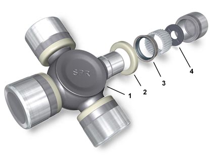 |
Spicer Life Series award winning universal joint kits are specifically designed to give extended driveshaft life. Flat ended needle bearings are used to withstand oscillating loads while the driveshaft is rotating and to eliminate skewing in the bearing cup. Thrust washers significantly reduce end galling on trunnion ends and lower universal joint operating temperature. Synthetic rubber seals and plastic seal guards provide lubricant retention and help prevent the entry of foreign material, significantly increasing universal joint life. The centrally located grease zerk (nipple) fitting increases the strength of the journal cross and allows more torque carrying capacity. | |||||||||||||||||||||||||||||||||||||||||||||
Features include: Cold-Formed Journal
Cross |
||||||||||||||||||||||||||||||||||||||||||||||
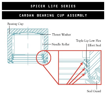 |
Triple-Lip
Seal Enhances grease retention and prevents contamination in the bearing assembly by utilizing three lips instead of two. Composite Thrust Washer Spicer Life series u joints feature a thermoplastic thrust washer in the bearing cup. This Eliminates metal-to-metal contact between the trunnion end and bearing cup. Prevents wear and end galling, and lowers the overall operating temperature of the universal joint. |
|||||||||||||||||||||||||||||||||||||||||||||
To lube or not to lubeSo the only remaining question is - do I use permanently sealed U-joints or re lubable U-joints (assuming there is a choice in the size/series you are using) This is not so simple to answer, and has long been the topic of many fierce debates. It may well come down to personal preference, but there are some points to consider. Most importantly - relubable U-joints MUST BE re lubed. It sounds obvious, but the one thing you do not want to do, is to kid yourself that you will do regular routine maintenance on your driveshaft and U-joints, and the not. And yet, this is exactly what a HUGE number of people do. Avoid it. Be honest with yourself. If you aren;t going to re lube them - use the "permanently" sealed kind, if not, you will experience premature failure. So, we have to be brutally honest with ourselves, fine. But what if we are the kind that actually would re lube the joints EACH and EVERY time they require it, properly, completely (see Part 3), and without fail (am I making a point here? There aren;t many people who fit into this category). Is there then any reason to prefer on kind over the other? You have to decide for yourself, but some advantages and disadvantages to consider are: Re-lubable
Sealed
Personally, I choose to run Spicer Life Series permanently sealed (NON-relubable) U-joints in my 1350 CV driveshaft, for the following reason: With my type of rig and the wheeling it does, the fact that it's a trailer queen, sees very little high speed use, sees very little total mileage in a year, and yet must be as strong and reliable as possible - I need to squeak every little bit of strength I can from every component, and things are much more likely to break catastrophically way before their time, rather than wear to due to a lack of lube. Spicer Life Series Universal Joint Cross-Over Index:
Causes, Analysis, and remedies for Driveshaft failureCauses and remedies of driveshaft vibration include:
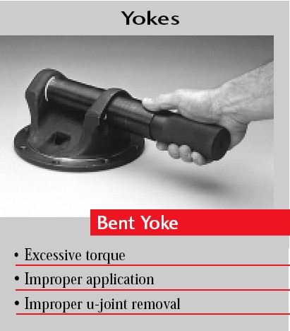
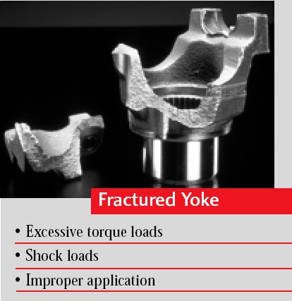
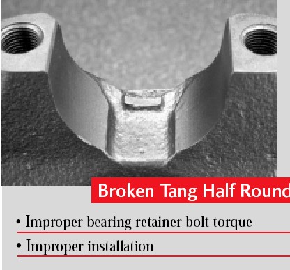
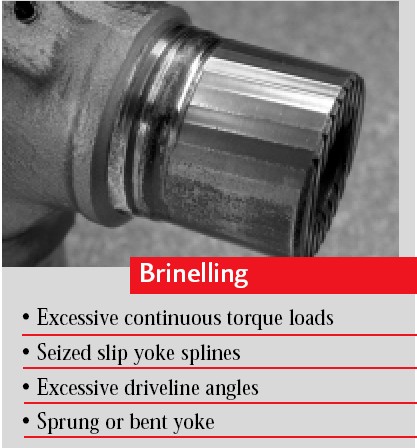
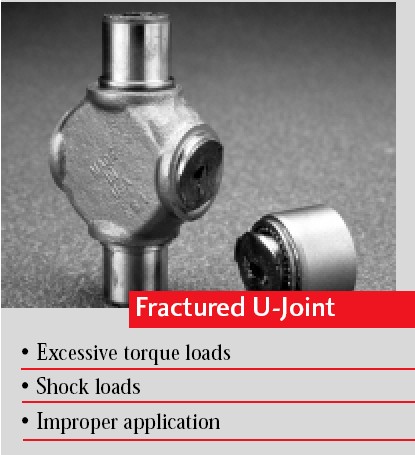
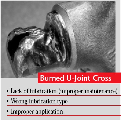
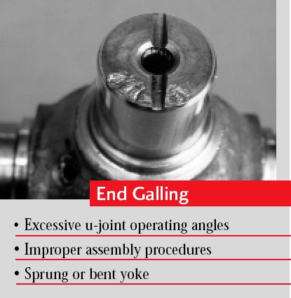
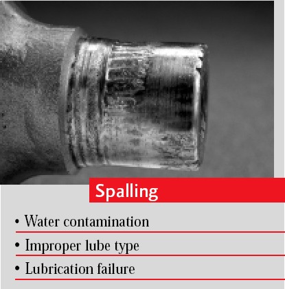
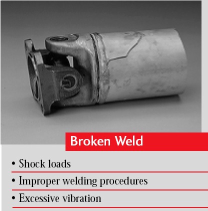
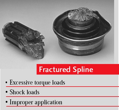
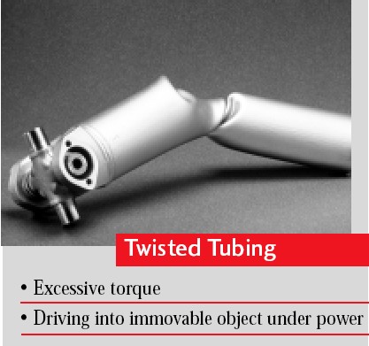
Driveshaft Failure analysis Guide
|
||||||||||||||||||||||||||||||||||||||||||||||
|
||||||||||||||||||||||||||||||||||||||||||||||
Sources: High Angle DrivelineJesse Jaynes (530) 877-2875 |
|