 |
Steel & Materials Strength By Bill "BillaVista" Ansell |
IntroductionThe title of this part, "The Tech behind the Talk", says it all. In this article we will examine in some detail the subject of "Materials Science", focusing primarily on steel and other ferrous metals. It will attempt to educate the reader on the composition of steel, it's properties and how to properly interpret them, as well as examine the many different types of steel and their uses, and much, much more. As usual, I also hope to dispel some of the vast amount of misinformation that exists surrounding the subject. |
 |
The purpose of all this is threefold: 1) First and foremost to educate the reader, so that they may be better armed to wade through all of the marketing hype involved with 4x4 products. Armed with this knowledge the reader should be better able to determine for themselves who builds and markets the "best" or "strongest" parts, which manufacturer's really know what they're doing, and who is just "blowing smoke" and trying to capitalize on the latest marketing buzz-words like "alloy", and "chrom-moly". 2) As a secondary goal, I hope to present enough information to assist the reader in selecting material most appropriate for their own construction and fabrication projects, at least within the confines of the disclaimer. At the very least I hope to illuminate the subject enough to motivate the reader to further research or at least begin to ask the right questions. 3) Part 1b is a special section that focuses on a subject that is near and dear to my heart, as well as being one of the least understood yet most frequently asked about topics of all time - axle shaft technology. Why would I write this, and why should
you care? It is the intention of this article to address these issues by arming you, the reader, with the ability to calculate where possible, and judge where required, what would be a reasonable material choice for your project, the best material for the parts you wish to buy, etc. Why steel, in particular? Disclaimer This article is written by the layman (me) for the layman. I am not an engineer, physical chemist, physicist, or metallurgist. Neither am I a machinist, millwright, or certified welder. I am a shade-tree fabricator – just like the majority of you. I can cut, shape, and join metal – subject to the limitations of my limited and non-professional tool collection. All of which is to say – USE THE INFORMATION HERIN WITH CAUTION - AND AT YOUR OWN RISK. This article is not an engineering text, it is not a specific guide to anything – it is background knowledge that you will have to apply yourself, in a manner in which you choose. Acknowledgements Throughout this article I have borrowed heavily from many texts, and 3 in particular. I encourage everyone with any interest in the subject to purchase and read these fine books, as they are chock full of excellent information (much more than I can cover here), and well written. They are: |
||||||||||||||||||||||||||||||||||||||||||||||||||||||||||||||||||||||||||||||||||||||||||||||||||||||||||||||||||||||||||||||||||||||||||||||||||||||||||||||||||||||||||||||||||||||||||||||||||||||||||||||||||||||||||||||||||||||||||||||||||||||||||||||||||||||||||||||||||||||||||||||||||||||||||||||||||||||||||||||||||||||||||||||||||||||||||||||||||||||||||||||||||||||||||||||||||||||||||||||||||||||||||||||||||||||||||||||||||||||||||||||||||||||||||||||||||||||||||||||||||||||||||||||||||||||||||||||||||||||||||||||||||||||||||||||||||||||||||||||||||||||||||||||||||||||||||||||||||||||||||||||||||||||||||||||||||||||||||||||||||||||||||||||||||||||||||||||||||||||||||||||||||||||||||||||||||||||||||||||||||||||||||||||||||||||||||||||||||||||||||||||||||||||||||||||||||||||||||||||||||||||||||||||||||||||||||||||||||||||||||||||||||||||||||||||||||||||||||||||||||||||||||||||||||||||||
 |
Engineer to Win
: The Essential Guide to Racing Car Materials Technology or How to Build
Winners Which Don't Break by Carroll Smith Paperback - 280 pages (April 1985) Motorbooks International; ISBN: 0879381868 |
|||||||||||||||||||||||||||||||||||||||||||||||||||||||||||||||||||||||||||||||||||||||||||||||||||||||||||||||||||||||||||||||||||||||||||||||||||||||||||||||||||||||||||||||||||||||||||||||||||||||||||||||||||||||||||||||||||||||||||||||||||||||||||||||||||||||||||||||||||||||||||||||||||||||||||||||||||||||||||||||||||||||||||||||||||||||||||||||||||||||||||||||||||||||||||||||||||||||||||||||||||||||||||||||||||||||||||||||||||||||||||||||||||||||||||||||||||||||||||||||||||||||||||||||||||||||||||||||||||||||||||||||||||||||||||||||||||||||||||||||||||||||||||||||||||||||||||||||||||||||||||||||||||||||||||||||||||||||||||||||||||||||||||||||||||||||||||||||||||||||||||||||||||||||||||||||||||||||||||||||||||||||||||||||||||||||||||||||||||||||||||||||||||||||||||||||||||||||||||||||||||||||||||||||||||||||||||||||||||||||||||||||||||||||||||||||||||||||||||||||||||||||||||||||||||||||
 |
Machinery's Handbook Tool-Box
Edition by Erik Oberg (Editor), Christopher J. McCauley (Editor), ricca Heald, Franklin Day Jones, Henry H. Ryffel 2640 pages 26 edition (April 15, 2000) Industrial Press, Inc.; ISBN: 0831126256 |
|||||||||||||||||||||||||||||||||||||||||||||||||||||||||||||||||||||||||||||||||||||||||||||||||||||||||||||||||||||||||||||||||||||||||||||||||||||||||||||||||||||||||||||||||||||||||||||||||||||||||||||||||||||||||||||||||||||||||||||||||||||||||||||||||||||||||||||||||||||||||||||||||||||||||||||||||||||||||||||||||||||||||||||||||||||||||||||||||||||||||||||||||||||||||||||||||||||||||||||||||||||||||||||||||||||||||||||||||||||||||||||||||||||||||||||||||||||||||||||||||||||||||||||||||||||||||||||||||||||||||||||||||||||||||||||||||||||||||||||||||||||||||||||||||||||||||||||||||||||||||||||||||||||||||||||||||||||||||||||||||||||||||||||||||||||||||||||||||||||||||||||||||||||||||||||||||||||||||||||||||||||||||||||||||||||||||||||||||||||||||||||||||||||||||||||||||||||||||||||||||||||||||||||||||||||||||||||||||||||||||||||||||||||||||||||||||||||||||||||||||||||||||||||||||||||||
 |
High Performance Hardware :
Fastener Technology for Auto Racers and Enthusiasts by Forbes Aird Paperback - 192 pages 1 Ed edition (April 1999) Berkley Pub Group; ISBN: 1557883041 |
|||||||||||||||||||||||||||||||||||||||||||||||||||||||||||||||||||||||||||||||||||||||||||||||||||||||||||||||||||||||||||||||||||||||||||||||||||||||||||||||||||||||||||||||||||||||||||||||||||||||||||||||||||||||||||||||||||||||||||||||||||||||||||||||||||||||||||||||||||||||||||||||||||||||||||||||||||||||||||||||||||||||||||||||||||||||||||||||||||||||||||||||||||||||||||||||||||||||||||||||||||||||||||||||||||||||||||||||||||||||||||||||||||||||||||||||||||||||||||||||||||||||||||||||||||||||||||||||||||||||||||||||||||||||||||||||||||||||||||||||||||||||||||||||||||||||||||||||||||||||||||||||||||||||||||||||||||||||||||||||||||||||||||||||||||||||||||||||||||||||||||||||||||||||||||||||||||||||||||||||||||||||||||||||||||||||||||||||||||||||||||||||||||||||||||||||||||||||||||||||||||||||||||||||||||||||||||||||||||||||||||||||||||||||||||||||||||||||||||||||||||||||||||||||||||||||
Much technical data was also gleaned from the following sites: http://www.steeltubeinstitute.org/ I am also greatly indebted to the following technical experts, most of them professional engineers, all of them gentlemen. Without their selfless sharing of technical facts and information I would never have been able to understand all of this: Thanks to: Gordon, PIG, Ed Stevens, Dave Kamp And very Special thanks to: Robin Ansell, Goat1 and lt1yj Table of Contents
Section 1: Steel basicsWhat
is steel? Yea, great – but really – what is a metal, in terms of what we care about? Metals are materials that:
Steel, in my humble opinion, is the king of all metals, having the best of all these properties - especially considering its weight and cost. So, in summary, steel is a metal that can easily be formed into useful parts, can resist high levels of load or force without breaking, and can change shape (bend) in response to a load and spring back to original shape. Why
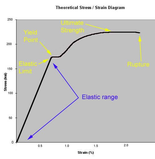
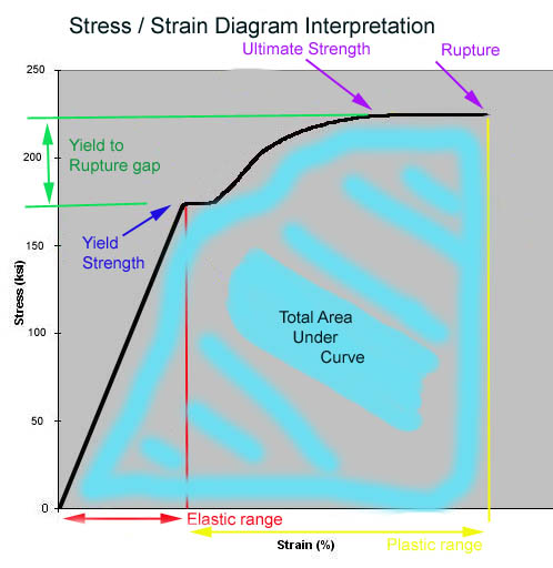
steel? As, noted, the reason steel is so strong and yet flexible and formable is very complicated, but the answer all boils down to it's atomic structure and the building blocks this atomic structure leads to, that all interconnect and build on one another until we have the actual steel. Let me explain a bit further. Not surprisingly, the answer lies deep within its atomic structure. All I will say here, is that metals are made up of atoms that have strong flexible atomic bonds, lie in very close formation and that are arranged in a regular and repetitive fashion into crystal unit cells of various shapes which are, in turn, built up, Lego-like, on a regular and repetitive 3-dimensional lattice structure into crystals of metal called “grains”. The nature of these atomic bonds, and the resulting crystal lattice structure, is what lends metals, and particularly steel, it’s combination of strength, hardness and malleability. In a gross over-simplification, we can say that steel atoms bond and form crystals, small crystals, or "grains" of metal join together to form a crystal lattice structure, much like bricks join together to form a wall. Continuing our brick wall analogy: the nature of the crystal lattice structure - i.e. how regular the grains are in shape and orientation - determines the properties (and chiefly of interest to us, the strength) of the metal. In much the same way as the shape and orientation of the bricks in a wall determine the properties or strength of the wall. Compare an old-fashioned stone wall constructed from stacked boulders and stones to a modern wall of precisely arranged rectangular concrete blocks. There are many factors that determine the size, shape, and orientation of the grains and crystal lattice structure, many of which we can manipulate. It is these factors and their manipulation which really interests us. The factors range from the atoms themselves i.e. the composition or "alloy" of the steel, to the shape and orientation of the grains - affected by things like forging, heat treating, cold working etc. One more brick-wall analogy: The bricks, their size, shape, and orientation to one-another determine not only how strong a wall is - but also in what way it is strong. For example, an old fashioned rock wall may have a great deal of strength if we bear down on it from above - i.e. set something heavy on it and it will easily support the load. However, lean against it sideways and it may easily topple over. In much the same way, the different ways in which we manipulate and treat steel can impart many different properties or "strengths" from compressive strength to shear strength - more on this later. Ultimately, it's all in the atomic and inter-atomic bonds. How we forge the steel from ore, what alloying elements we add to it, how we "work" it, and even how we machine and weld the final product will all have an impact on the atoms/grains/crystal lattice structure - and therefore strength and properties of the steel. Understanding how this happens and why is chiefly the goal of this article. As a point of trivia, there is no such thing as a “molecule” of steel. In fact, metals, as a family of elements, are distinguished from other elements in part because their crystalline structure is made up of individual atoms (they are monatomic) as opposed to molecules. Where does steel come from? Steel is not a naturally occurring substance - it is entirely man made. Steel is chiefly a combination of two naturally occurring elements: iron and carbon (along with small amounts of other elements - depending on the steel in question). The process by which man makes steel, would, again, fill several volumes. Here is my amateur synopsis: Iron is mined from the ground in the form if a reddish-brown rock called iron-ore. This ore is then smashed up, strained, filtered, chemically treated etc, until ultimately it is melted in huge blast furnaces into something called pig iron. The process uses coke (a type of coal), which in turn imparts large amounts of carbon to the pig iron. As a result, pig iron itself is full of impurities, brittle, and unmachinable - practically useless. Except - it is the raw material from which all other irons and steels are made. Pig iron is so produced in either huge vats of molten material, or it is cast into ingots (in fact, pig iron got it's name because the ingots or "chunks" produced were thought to have resembled piglets). Pig iron is then refined into either metallic iron or steel using specialized furnaces and processes. The distinction between the two is that metallic iron has between 2-6% carbon content, and steel has <2% carbon content. Of course metallic iron is further refined into, and categorized as, many different types of iron - from grey cast iron to nodular iron; in much the same way as steel is further refined into and categorized from low carbon steel to alloy steel. We'll explore all of these in detail later. Metals like iron and steel, being largely composed of elemental iron, are known as "ferrous" metals after the chemical symbol for elemental iron - Fe. A final word about carbon. carbon is critically important to our whole discussion because it is the presence of carbon that turns the element of iron that is naturally soft and weak, into the strong, rigid materials we know as iron and steel. Precisely how this is so is beyond the scope of this article, suffice to say: The strength, hardness and toughness that make the ferrous based metals useful to us are profoundly influenced by the remarkable sensitivity of the physical and chemical properties of iron crystals to relatively small percentages of carbon dissolved within their matrixes (actually, the sensitivity is to the movement of dislocations within the crystal space lattice). This sensitivity to dissolved carbon is in fact, the very basis of ferrous metallurgy. [1] A poor, but perhaps useful metaphor may be the use of fibre-mat and resin in fibreglass work. The bulk raw material of fiberglass is the fibre matting (as iron is to steel) - but by itself the matting is of no practical use. Not until we add the resin to it to make fibreglass (as we add carbon to iron to make steel) do we get a useful product. In both cases, neither raw material is much use alone, but combine them and we really have something. Similarly, though carbon may only be present in small quantities, just as the amount of hardener added to fibreglass resin has a profound effect on the material, so does the small amount of carbon present in useful metallic iron and steel. Section 2: Stress and StrainYou may have noticed that we have already bantered around a bunch of terms that we really should define - just so we're on exactly the same page. And there's many more terms to come. So lets lay out some initial definitions now. Strength - a measure of how strong something is! ha ha! Seriously, this is a very important definition, as this entire series of articles is, in large part, just about how strong things are. Not only that, but the truth is not nearly as simple as my little joke above would lead you to believe. In the broadest of terms, when we speak of a substance or products strength, we are talking of it's ability to resist an external force or load, without deforming, breaking or rupturing. Technically we say a materials strength is the greatest stress it can endure without rupturing (by rupturing - I mean the atomic bonds coming completely apart.) There are many specific kinds of strength, from the "pure 3" - tensile, compressive, and shear to complicated combinations such as torsional and bending. We will examine each of these in detail throughout the article. Stress. We all know instinctively that, generally speaking, if we have 2 things made from the same stuff, that the larger will be "stronger". In order for us to be able to discuss the strength of material, and particularly to compare different materials, we need a way to compare strength without constantly referring to how big something is. That is, we need to be able to eliminate size as a factor. We do this by employing the concept of stress. Stress is a force or load applied, divided by how big the part is, in other words force per unit of cross sectional area. It is common to measure the force applied in pounds and the cross sectional area in square inches. Thus, the unit for stress is pounds per square inch, or PSI Using the concept of stress, we can now compare relative strengths regardless of size. Say we have 2 steel bars, one is 1 square inch in cross sectional area, the other 1/2 sq. in. If they are both made from a material having a breaking strength of 10,000 psi, one will break when 10,000 lbs is applied, the other when 5,000 lbs is applied, despite that they are made from the same material. Conversely, if we have 2 products of unknown or difficult to determine size but we know that one is made from a material with a yield strength of 75,000 psi and the other 100,000 psi, we know that the second is made of a stronger material (regardless of comparative size), and we can also say that the first would have to be 25% greater in size to be of equal strength. This logical approach can lead us to quite accurately determine that, if the sizes are similar, the second is definitely the stronger product. Strain - closely allied to the concept of stress - the concept of strain allows us to quantify or describe how a part or material responds to an applied force or load. Quite simply: Strain is a change in shape or dimension in response to a stress. It is usually expressed in percent elongation (%) Percent elongation is the difference in length between the original length of a test specimen (often 2" in length) and that same specimen after it has been ruptured by a tension load. In other words, materials STRAIN to resist a STRESS (much like people do to!). Stress and strain are two separate, useful concepts but the real power of these concepts is only realized when the 2 concepts are combined. There is a defined relationship between stress and strain, discovered by an English bloke in 1680, that states the strain of any material is proportional to the stress within it. It is known as Hooke’s law and is simply stating what you already know – “the harder I push on this, the more it will bend……”. What’s important though, is that, up to a point, this relationship is proportional, or linear…meaning that if I push twice as hard, it will bend twice as far. The point up until which this is true is called the elastic limit. Realize that Hooke's law applies not only while a load (stress) is applied, but also when it is removed. Meaning, as long as we are within the elastic limit of the material (i.e. the stress is less than the elastic limit of the steel) strain is always proportional to stress, meaning if stress (load) is zero then so too is strain (distortion). What we have just described is one of the most righteous properties of steel. That is, it is "elastic" in nature - which is a fancy way of saying: up to a point, we can bend it by applying a load, then if we remove the load it will "spring" back to exactly the same shape and size it was originally. We call this elastic deformation. Of course, we can apply a stress that exceeds the elastic limit of the steel, and if we do, the steel changes from elastic in nature (able to spring back) to plastic in nature - meaning the stress applied, once it passes the elastic limit, will result in a permanent change in shape of the metal. This we call plastic deformation. Another quote from Mr Smith is in order: A solid is considered to be elastic if, after a change of shape due to an external load, the body returns to its original size and shape when the load is relaxed. Plasticity, in the metallurgical sense of the word, is the ability of a metal to be deformed beyond its range of elasticity without fracture; the result is a permanent change in shape. These two related properties are the most significant of all the characteristics of the family of metals. Plasticity gives us the ability to form metals into useful shapes and elasticity allows us to use metal fabrications as load-bearing members in our structures. [2] You can begin to see now, how with a little knowledge, and an idea of the stress/strain diagram we can solve forever the arguments of whether something is stronger than something else, whether it is "too brittle" or will "bend before it breaks" etc. Let's examine a sample, theoretical graph of stress vs strain, called a stress/strain diagram
There are a few important concepts to note here:
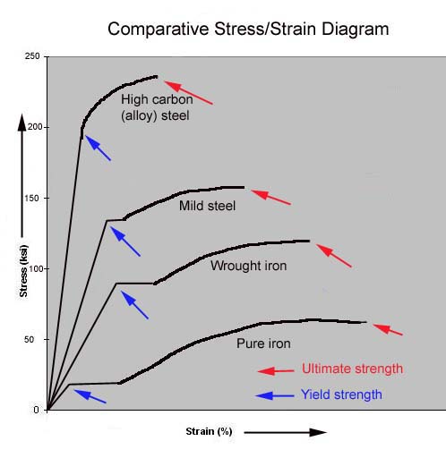
Comparative stress/strain diagrams Now that we have a good idea of all that the stress/strain diagram illustrates, it is extremely educational to examine some comparative stress/strain diagrams.
Examining this diagram carefully, we can learn much about the properties of different materials, and ultimate ly that materials suitability for a given part. Note: Again, this diagram is for illustrative purposes, the actual scale of numbers used are not real, but are for illustration only - the relative shape and size of the curves between the different materials is real however. It is the concepts that are important. A good understanding of what is really going on here can help us understand much of the "common wisdom", as well as the persistent myths that are out there regarding steel and iron parts - from the "grade 8 bolts are too brittle" nonsense to other commonly held misconceptions about cast iron and steel. The differing yield strengths of the different materials are indicated by the blue arrows, and the ultimate strengths the red arrows. Note:
These last 2 points are the root of what I see as one of the most often misquoted and most poorly understood concepts of material strength - the interrelationship between ductility and strength. Take for example the classic misconception/myth: "Grade 5 bolts are a better choice than Grade 8 because the grade 8 are too brittle and will snap, while the grade 5 will bend before breaking". By examining the above stress/strain diagram and imagining the grade 5 bolts represented by the "mild steel" curve and the grade 8 bolt by the "alloy steel' curve (accurate enough for our purposes) we can clearly see both the underlying "truth" in the myth, as well as the great error that ultimately leads it to be an incorrect statement and a very poor guide for bolt choice in all but a very few cases. First the "truth". We can see from the curve, that indeed, the grade 5 bolt will deform more (exhibit greater strain) between yield point and rupture. However, the myth neglects two critical factors that become abundantly clear when looking at a stress/strain diagram:
And finally, one more kernel of "truth" to the myth. The one place the grade 5 may be superior is in the area of "impact strength" or "toughness". By impact strength we mean the ability to withstand a sudden impact or shock load. An example might be when a snowplow running through powder at 30 mph suddenly hits an 8" concrete curb (ouch!) The loads imposed by such a sudden impact are exponential, off the chart, and hard to calculate or predict accurately. Remember that we said that the total area beneath the curve is an indication of the materials toughness, and that toughness was the ability to absorb energy? This ability to absorb energy is exactly what we need in the case of a severe impact shock load, and we can see that the area beneath the "grade 5" curve is greater than beneath the "grade 8" curve. Having said that though - the grade 5 bolt subjected to a shock load is ONLY a better choice because it may allow you to limp home without the plow (or whatever) separating from the truck - the bolt will almost certainly still have passed the yield point and has technically "failed" and therefore requires replacement. This case study is but one example of how we can apply a true and accurate understanding of materials, specifically stress/strain diagrams, to either our own part fabrication or our judgement of which part is really "strongest", "best", or "most suitable". Essentially, the choice of a material for any given structural duty or load bearing part boils down to a considered compromise or trade off between how high and steep the curve is (the yield strength) and how long it is (how much it can deform before rupturing), and the height between yield and ultimate strength (how much more stress it can take since yielding before rupturing) Ultimately, we can label a stress/strain diagram slightly differently to help us understand the qualitative and quantitative differences between different materials. I have chosen to do so like this:
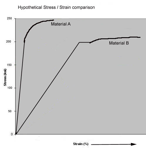
One final point - remember - it is the whole stress/strain curve that really describes how a material will react under load - the size, shape, etc. - NOT just any singular value (this, in fact shows the fallacy we indulge in when we blithely compare products by quoting just a single property - like ultimate tensile strength or the like). Compare, if you will, the following 2 curves for 2 different, completely hypothetical materials. Note from the curves that, though they share very similar values in yield strength and even similar ultimate strength, they are VERY different materials and will react under load in very different ways - making them potentially much more or less suitable for any given use. Study the diagram, and once you completely see and understand this, you are ready to proceed, young grasshopper!
Section 3 - The Critical DefinitionsNow, it would be impractical for us to try and communicate about different materials and parts simply by comparing stress/strain diagrams, despite the great amount of information they portray; not to mention how complicated it is to collect the data to plot an actual graph. As such, we have a whole vocabulary surronding metal parts that we use to describe the properties of various steels, and the parts made from them. Here are some of the most important definitions. Note how they can all be derived from, illustrated by, or relate back to the stress/strain diagram. Hardness – is the property of resisting penetration. Normally, the hardness of steel varies in direct proportion (i.e. as one gets bigger so does the other and vice versa) to its strength – the harder it is, the stronger it is, and vice-versa. Brittleness – is the tendency of a material to fracture without changing shape. Hardness and brittleness are closely related. The harder (and therefore stronger) a metal is, the more brittle it is likely to be. Materials that are too brittle will have very poor shock load resistance. Malleability – is the opposite of brittleness. The more malleable a material, the more readily it can be bent or otherwise permanently distorted. As hardness was closely related to strength, so then is malleability. Generally, the more malleable a metal, the weaker it is. Ductility – much like malleability, ductility is the ability of the material to be drawn (stretched out) into thin sections without breaking. The harder and stronger a metal is, the less ductile, and vice versa. Toughness – The ability of a metal to absorb energy and deform plastically before fracturing. It is usually measured by the energy absorbed in an impact test. The area under the stress-strain curve in tensile testing is also a measure of toughness. You can see how there is a trade-off between a metal’s malleability/ductility and its hardness/strength (which makes perfect logical sense – since malleability is the ease with which we can form it, by applying force, and strength is its ability to resist force). There are a whole group of people employed in a field called “physical metallurgy” whose job it is to figure out how to use things like alloying, heat treatment, and cold-working to skew this relationship (malleability/strength) in our favour, so that hopefully we can develop materials that are both strong and malleable. It will, of course, come as no surprise that their best efforts cost the most money - aint it always the way! We'll be looking at what they've come up with so far in a little while. Before we begin our examination of specific steels and treatments, there are a couple more principles we need to get under our belts - the modulus of elasticity and the concept of stiffness. Modulus of elasticity and the concept of stiffness. Intuitively we all know that load bearing parts must be strong, must be built from material that is strong. But there is more to it than that. We already defined strength as the greatest stress a material can endure without rupturing. But that's not all - for given just that definition - we could decide to build load bearing parts out of soft materials that are strong - like copper and rubber - they can tolerate large loads without rupturing. However, we know instinctively they wouldn't be suitable for building bridges, buildings, crankshafts, frames and axles - they are too flexible and while not rupturing under the load - they would deform too much. So - what we need is a material that while strong, will also resist deforming under load - we call this property STIFFNESS. We need load bearing parts made from strong (so they don't break) and stiff (so they can bear the load without excessive deformation) materials. How do we determine what materials are suitably "stiff" as well as being strong? The problem is complicated by the fact that how stiff something is, is a function of not only the material, but also the shape. For example, take a piece of paper - not very stiff is it? Now roll it into a tube and press it together lengthwise - pretty stiff eh? In much the same way as we use the concept of stress to isolate strength due to material from strength due to size; so we need a way to isolate stiffness due to structure (shape) and stiffness due to material. Another English guy figured it our for us. In 1800 English physicist Thomas Young discovered that he could rewrite Hooke's law to read "for any material, stress divided by strain is equal to a constant". What this deceptively simple statement hides is the very fabric of all structural design engineering - namely that elastic materials, such as steel, all have a unique "constant of elasticity" that describes the materials elasticity - it's ability to spring back into shape after a stress is removed. This constant of elasticity is a measure of how stiff the material is - the larger the constant, the larger the stress than can be applied without exceeding the elastic limits of the material, and the stiffer the material. This "constant" is unique and constant for each material, and is known as the Young's modulus or the "modulus of elasticity" of the material. In order to be able to compare materials, in much the same way as there is s standard way to measure yield strength (stress required to produce 0.2% elongation), there is a standard way to calculate Young's modulus. Young's modulus is defined (and calculated) as the the stress required to double the length of a test specimen. Obviously this is a theoretical value, useful only for comparing materials stiffness, as no structural material on earth can actually be doubled in length without rupturing. The modulus of elasticity for all steels is about 30, 000, 000 psi !!!! Stop! Read that again! Yes, that's right - the modulus of elasticity is the same for ALL steels. This means they are all comparably stiff, they will ALL resist bending or twisting about the same amount - from cheap pipe to expensive cr-mo tubing. The difference between them is what happens when they bend - in other words, the stress/strain curves are different. The better, more expensive steels, due to their much higher yield points and greater elastic ranges, will be able to easily shrug off the load, wheras the lesser material may yield (take a permanent set, or bend) or actually rupture. This is very important, and hugely misunderstood concept, so I'll repeat it. All steels will bend or twist the same amount under the same load - the difference is in how they handle this loading - good steel will "spring back", poorer steel will bend permanently or break. Mathematical proof of this comes from the equation used to determine how much a tube will deflect under a given load. The equation is: P*L / (E*I) where: P = the load (force) placed on the
tube (lbs) In comparing 2 tubes, the only factor in this equation that can change is the Moment of Inertia, I The formula for calculating I for any tube is: I = (0.049*OD^4) - (0.049*ID^4) Where: OD = the outside diameter of the
tube Note that the equation does not take into account anywhere the type of steel the tube is made from. The factors that effect how much the tube will deflect, or bend, are just the OD and ID of the tube (or OD and wall thickness if you prefer, it amounts to the same thing); with OD being the much more powerful determining factor. Now, you might reasonalby ask - why build anything of expensive steels then? Where are the equations to deal with that? Remember, the tube will deflect the same amount, but whether it survives that deflection is where we get into the difference between steels, using the concept of yield strength. How much load the tube can handle before yielding (changing shape permanently) is calculated as: Ld = 2*I/OD*Fy/L Where: I = I = Moment of Inertia This last factor, Fy, is where the different steels will have hugely different values - from 30,000 psi for A-53 welded pipe to 240,000 psi for quenched and tempered 4340 Cr-Mo tubing. I should point out that these equations are shown simply for the purpose of understanding and illustrating the concepts discussed: DO NOT USE THEM for calculations, as they may not include critical elements such as design factor, impact loads, safety margins, and fatigue factors! (that's what professional Engineers are for :-) Mr Smith summarizes quite nicely: "We do not build structures from materials with low moduli of elasticity [non-stiff, flexible] simply because such structures would sag under any reasonable load...We do not make structures from weak materials simply because such structures would break under load. Together the two properties of stiffness and strength define the physical properties of a solid material. For instance:
And finally, before moving on to the next section, we shall now cover some of the other more commonly encountered and more important definitions. Other definitions are covered in the glossary:
Section 4 - The Steels of interest to us.OK - hopefully we now have a good comprehensive understanding of what the different properties of materials are - from elastic range and yield strength to ductility and ultimate strength. Now what we need to do is develop and understanding of how and why some materials have these differing properties, followed by looking at the actual and relative properties of different irons and steels we will encounter, and finally which we should choose (or demand our suppliers and manufacturers choose) and why. There are really three groups of metals that are of greatest interest and use to us, the builders and wheelers of hardcore 4x4s. They are all ferrous metals, meaning they are iron based and are magnetic. The groups are:
We will now examine each in a bit of detail. Cast Irons Ahhh - yes, the much maligned, hugely misunderstood cast iron. Let me get this off my chest right now. The term CAST IRON does not refer to a specific material with properties that we can discuss. It is a GENERIC TERM for a whole group of ferrous metals that are made up of iron, silicon, and carbon. The name has 2 parts - CAST referring to the fact that these metals can be readily poured into moulds (cast) when molten, to make parts, and IRON for the chief element that makes them up. It is sometimes (though rarely) necessary, and therefore just barely acceptable, to use the term "cast iron" when referring to the material from which something is made - but ONLY if we do not know the more specific type of cast iron. It is NEVER acceptable (though vast numbers of derelicts and miscreants are guilty of it!) to shorten this further and refer to any material by calling it 'cast' and using the word cast as a noun. In our world, "cast" is a verb, and is the method of making a part by pouring molten metal into a mould. There, I feel better, don't you? Now, there are several different types of cast irons that we should know about, and within each type there are often several different "grades." The different types of cast iron are distinguished by the form which the carbon takes - be it carbides, graphite, flakes, nodules, etc. The different types are: Gray Iron White Iron Malleable Iron Nodular (Ductile) Iron One of the most popular examples of nodular iron applicable to us must be the famous Ford 9 inch rear axle with the highly sought after nodular housing. Note also that some popular Dana axles (center sections) are cast from malleable iron (e.g. Dana 30) and some from Nodular Iron (e.g. Dana 44, 60) Carbon Steels It stands to reason that we cannot possibly describe or compare something unless we have a common language and a way to ensure we're talking about the same thing. In other words, a way to make sure we are comparing 'apples to apples". This is, in fact, one of the areas most full of error that I encounter on the web - people are not comparing "apples to apples". Hopefully, after reading this section, we will all be able to do so more accurately. Steel Designations. Numbering systems currently in use today for steel have been developed over the years by various groups, including: trade associations, engineering societies, standards organizations, and private industry groups. Some examples are those developed by the American iron and Steel Institute (AISI), Society of Automotive Engineers (SAE), American Society for Testing and Materials (ASTM), American National Standards Institute (ANSI), Steel Founders Society of America, American Society of Mechanical Engineers (ASME), and the American Welding Society (AWS). You can see how it would be easy to fall into the trap of comparing apples to oranges! Not to worry, for our use, it's pretty easy as we generally stick to SAE/AISI designators. If you have or come across a steel with a different designator, there are many good trade publications that contain tables showing equivalent designations. All carbon steels, the types we are interested in, (at least in North America) are designated using a standard four digit numbering system developed in cooperation between the American Iron and Steel Institute (AISI) and the Society of Automotive Engineers (SAE). For example, we are often used to seeing different steels referred to as 1020 or 4130 or 4340. The numbers are not arbitrary, they have specific meaning, and can tell us a lot about the steel in question. The first 2 digits of the designation are the "classification" of the steel. Carbon steels all belong to one of four (4) classifications, only two of which are any use to us - the 10xx and the 15xx. The four classifications of carbon steel are: 10xx—nonresulfurized carbon
steel. Basic structural "low-carbon" or "mild" steel. The last two digits of the standard four digit designator indicate the approximate carbon content of the steel in tenths of a percent. For example, SAE 1020 contains approximately 0.20% carbon (actually from 0.17% to 0.23%). Recall that the higher the carbon content the higher the ultimate tensile strength—and the lower the ductility. Sometimes a suffix H is attached to a AISI/SAE number to indicate that the steel has been produced to prescribed hardenability limits. For example 1541H is a commonly used carbon steel in the manufacture of axle shafts. There are a great many different specific types of carbon steel. The following information, taken from Carroll Smith's "Engineer to Win" and from the 24th Edition of the Machinery's Handbook (not the most modern, but the one I happen to own!) covers all or most of the types that are likely ever to be used by us to make parts from or used by manufacturers we might buy from. SAE 1010-1015 SAE 1018-1020 SAE 1025 And here's what the 24th edition of the Machinery's Handbook has to say on the matter: Carbon Steels,-- SAE steels 1006, 1008, 1010, 1015: These steels are the lowest carbon steels of the plain carbon type, and are selected where cold formability is the primary requisite of the user. They are produced both as rimmed and killed steels. Rimmed steel is used for sheet, strip, rod, and wire where excellent surface finish or good drawing qualities are required, such a body and fender stock, hoods, lamps, oil pans, and other deep drawn and formed products. This steel is also used for cold heading wire for tacks, and rivets and low carbon wire products. Killed steel (usually aluminium killed or special killed) is used for difficult stampings, or where non-aging properties are needed. Killed steels (usually silicon killed) should be used in preference to rimmed steel for forging or heat treating applications. These steels have relatively low tensile values and should not be selected where much strength is desired. Within the carbon range of the group, strength and hardness will rise with increases in carbon and/or with cold work, but such increases in strength are at the sacrifice of ductility or the ability to withstand cold deformation. Where cold rolled strip is used the proper temper designation should be specified to obtain the desired properties. With less than 0.15 carbon, the steels are susceptible to serious grain growth, causing brittleness, which may occur as the result of a combination of critical strain (from cold work) followed by heating to certain elevated temperatures. If cold worked parts formed from these steels are to be later heated to temperatures in excess of 1100 degrees F., the user should exercise care to avoid or reduce cold working. When this condition develops it can be overcome by heating the parts to a temperature will in excess of the upper critical point, or at least 1750 degrees F. Steels in this group, being nearly pure iron or ferritic in structure, do not machine freely and should be avoided for cut screws and operations requiring broaching or smooth finish on turning. The machinability of bar, rod and wire products is improved by cold drawing. Steels in this group are readily welded. SAE 1016, 1017, 1018, 1019, 1020, 1021, 1022, 1023, 1024, 1025, 1026, 1027, 1030: Steels in this group, due to the carbon range covered, have increased strength and hardness, and reduced cold formability compared to the lowest carbon group. For heat treating purposes they are known as carburizing or case hardening grades. When uniform response to heat treatment is required, or for forgings, killed steel is preferred; for other uses, semi-killed or rimmed steel may be indicated, depending on the combination of properties desired. Rimmed steels can ordinarily be supplied up to 0.25 carbon. Selection of one of these steels for carburizing applications depends on the nature of the part, the properties desired, and the processing practice preferred. Increases in carbon give greater core hardiness with a given quench, or permit the use of thicker sections. Increases in manganese improve the hardenability of both the core and case; in carbon steels this is the only change in composition that will increase case hardenability. The higher manganese variants also machine much better. For carburizing applications SAE 1016, 1018, and 1019 are widely use for thin sections or water quenched parts. SAE 1022 and 1024 are used for heavier sections or where oil quenching is desired, and SAE 1024 is sometimes used for such parts as transmission and rear axle gears. SAE 1027 is used for parts given a light case to obtain satisfactory core properties without drastic quenching. SAE 1025 and 1030, while not usually regarded as carburizing types, are sometimes used in this manner for larger sections or where greater core hardness is needed. For cold formed or headed parts the lowest manganese grades (SAE 1017, 1020, and 1025) offer the best formability at their carbon level. SAE 1020 is used for fan blades and some frame members, and SAE 1020 and 1025 are widely used for low strength bolts. The next higher manganese types (SAE 1018, 1021 and 1026) provide increased strength. All of these steels may be readily welded or brazed by the common commercial methods. SAE 1020 is frequently used for welded tubing. These steels are used for numerous forged parts, the lower carbon grades where high strength is not essential. Forgings from the lower carbon steels usually machine better in the as forged condition without annealing, or after normalizing. [6] Some sample uses of 10xx and 15xx steels, taken from the Machinery's Handbook:
Adapted from: "Machinery's Handbook" 24th Edition. Erik Oberg, Franklin D. Jones, Holbrook L. Horton, Henry H. Ryffel, Robert E. Green; Industrial Press Inc., 1992 p.382-4 Alloy Steels Alloy steels are steels that have had finite and precise amounts of alloying elements added to them during their manufacture. Alloying Elements are chemical elements added for improving the properties of the finished materials. Some alloying elements are: nickel, chromium, manganese, molybdenum, vanadium, silicon, copper. Small, precise changes in the exact chemistry of the steel can change the mechanical properties quite drastically. Generally, alloying elements are added to steel to maximize some particular mechanical property(ies). Of course, nothing in life is free, and there is always a price to pay. The more alloyed a steel is, the narrower it's appropriate use, as it becomes more and more specialized (narrow in focus) There is also a trade off in the reduction of other properties: as hardness and strength go up due to alloying with chromium and molybdenum - ease of welding and ductility go down, and of course cost goes up - in some cases WAY up. Steel is considered to be alloy steel when the maximum of the range given for the content of alloying elements exceeds one or more defined limits. Common alloying elements and their effects are:
Alloy steels are also designated using a standard four digit numbering system, very similar to that used for the carbon steels. However, the first two digits indicate the major alloying element or elements, whereas the last two digits again indicate the approximate carbon content of the steel in tenths of a percent. For example, SAE 4340 contains approximately 0.40% carbon. The first two digits of an alloy steel's designation indicate the alloying elements and their percentages as follows: 13xx - Manganese-1.75 % Note that the hugely popular designation "Chrom-moly" steel has nothing to do with the shiny stuff on bumpers and hubcaps, but is in fact a reference to the fact that the steel in question has major alloying elements of Chromium and Molybdenum. That's why I prefer to write the abbreviation as Chrom-Moly, without the "e" on chrome. It is also popularly abbreviated as Cr-Mo, Cro-Mo, etc. Note that 41xx and 43xx alloy steels can and frequently ARE both refereed to as "Chrom-Moly Steel", though obviously the 43xx also has significant Nickel added. Some characteristically enlightening, if rather opinionated, insight from my hero on the most common/popular alloy steels follows: SAE 4130 SAE 4140 SAE 4340 SAE 4340 MODIFIED (300M) THE HIGH SILICON, NICKEL CHROME
STEELS Mechanical Properties The following tables illustrate mechanical properties of various different types of steels of varying types - from hot rolled 1020 to cold finished 4340 chrom-moly alloy steel. They are taken from a variety of sources[8]. In addition to the actual specific numbers / data they contain, I believe they clearly illustrate some key concepts:
Section 5 - Steel ProductionHow Steel is made into the useful products we need. Recall that steel is produced from pig iron in a specialized furnace of a steel mill. This steel is produced in one of three special forms, known as slabs, blooms, or billets - each of which has an industry defined standard shape and size and which will be made into different useful products. Slabs eventually become steel plate, sheet metal or tubing. Blooms become something called "structural shapes" which we know as angle-iron, I-beams, etc. The last product is a billet, which is used to make solid steel bars and wire. Note that this is the correct use of the term "billet" - though we commonly misuse the term as either a noun meaning "any solid piece of metal from which we usually machine a part" or as an adjective meaning "a part machined from a single solid piece", as in "Look at my billet steering arms." Whichever the particular shape that is started with or the finished product that is desired, the essential process is the same. The raw steel shape is turned into a useful steel product by one or more of various mechanical means - the raw steel is either pressed, rolled, formed, stamped, forged, or extruded into the final product. Each of these methods can be conducted at temperatures close to room temperatures (cold working) or at much higher temperatures, up to where the steel is nearly molten (hot working), or some combination thereof (for example, a particular steel product could be hot forged and then cold-finished. Carroll Smith explains the process further: "In the process, the physical characteristics of the metal are improved by breaking up the "as cast" crystal structure and "refinement" of the grain size...The yield strengths of almost all metals decrease notably with increasing temperature, so that a given amount of deformation can be achieved at much lower stress levels if the material is hot worked rather than cold worked. ..Almost all of the energy expended in the hot working of metals is dissipated as heat, leaving the metal's crystal structure largely unaffected and the metal ductile. On the other hand, while most of the energy expended in the cold working of a metal is also dissipated in the form of heat, some part of this energy remains within the crystal structure of the metal itself as "strain energy" in the form of various distortions of and dislocations in the crystal space lattice. Therefore, cold working, by decreasing the grain size and increasing the number of dislocations in the crystal lattice of the metal being worked, can increase the strength and hardness of the finished product—sometimes to a notable extent—at some cost in ductility...As you would expect, the different mill forming processes result in steel mill products of varying qualities and properties:" TUBE AND PIPE STRUCTURAL SHAPES STEEL PLATE and SHEET BAR AND ROD STOCK-WIRE What's the difference to us, between hot and cold? Depending on the exact product (tube, pipe, flat bar, plate steel, etc) the type of steel (mild, high carbon, alloy etc) and the manufacturer - MOST steel products we might use are available as either hot rolled, cold rolled, or hot rolled and cold finished. The difference is:
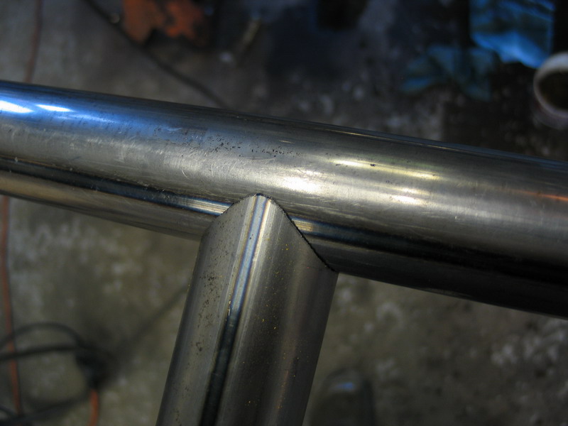
Steel Tubing It is impossible to go into details about every type and shape and grade of steel product available or that we might be interested in. There are far too many, and availability will vary greatly depending on location and manufacturer/supplier. That said, one of the most often used, most often asked about, and most often misunderstood products we use is the venerable round steel tubing. Round steel tube is commonly available in a number of industry standard sizes. For an idea of the common industry sizes (inside diameter (ID), outside diameter (OD), and wall thickness) browse the supply catalogue of your local supplier. My local supplier is Loucon Steel, and they have an excellent 70-page catalogue that lists all the commonly available dimensions for round, square, rectangular, plate, channel, I-beam, and sheet steel. Note that round steel mechanical tubing is NORMALLY ordered and supplied based on a specified OD and wall thickness. The ID is the result of these former 2 specs. There are however some exceptions to this - most notably in true seamless tubing. Here are some Flash™ graphics of the different steel tube forming processes that I snagged from the excellent Steel Tube Institute of North America website. Contnuous
(butt welded) pipe process. Typical
Electric Resistance Welded tube process DOM
tube being constructed, starting as ERW and then being drawn over a mandrel. Seamless
tube construction Steel tubing is usually supplied in one of the following forms: Seamless Tube.
Electric Resistance Welded
(ERW) Tube
Drawn Over Mandrel (DOM)
Alloy Steel Tubing Exact chemical content, heat treatment, physical properties, production method and therefore mechanical properties will vary from one supplier to the next, even for seemingly similarly named products - the wise fabricator double-checks all assumptions carefully before building anything. Different suppliers will also have available different products. For example, Ryerson, one of North America's largest suppliers list in their catalogue of steel tubing between 1" and 2' OD, the following types (not all available in all sizes):
Many suppliers will have such special proprietary products - you will have to check with your supplier for its proprietary product properties and specs. One thing that has to be watched out for is that the industry bends a lot of carbon steel tubing to make lots of things and so most carbon steel tubing is available in the annealed condition—woe to him who does not detect it before he builds the part. I have a very good friend who once got an entire roll cage cut, bent, fitted and tacked before he realized that his merry men were working with annealed boiler tube. The other thing that we don't want is "free machining tubing." I currently use round carbon steel DOM mechanical tubing for most things other than suspension links (there I use E4130N and stress relieve and heat treat after welding). For roll cages I use either 4130 or DOM 1020. I do not want to know about hot-finished tubing because I do not want to clean it. I am old enough to remember the days when English ERW tubing was liable to split along the weld seam. As a matter of principle (or, possibly, stubbornness) I do not use ERW or butt welded tube on the race car; although, since it is a lot cheaper, I use it all over the trailer and the shop.[11] My personal mantra on the subject of steel tubing choice for 4x4s and rock crawler's is:
Heat Treating Heat treating and hardness - Two terns you hear A LOT, and so you should, for they are a critical part of the puzzle. In fact, when determining a materials suitability for any given task or part, heat treating itself is probably THE MOST SIGNIFICANT factor. It goes hand-in-hand with the type of material. In fact, very often, the more exotic and expensive alloys steels are "stronger" or "better" because they can be heat treated and hardened more thoroughly or deeper. In other words, chrom-moly steel is not just a product with wondrous properties - it's also a steel with certain alloying elements added to it that allows it to be hardened , and therefore made much stronger and more wear resistant, than other steels. The trouble is - the topic of Heat Treating is HUGE, and quite complicated.....it involves physics, chemistry, math - all the fun Saturday night subjects :-) There is no possible way I can even scratch the surface in an article of this scope - but I can drop a little knowledge in the bucket of your collective minds, so that at least you will have a passing idea when you see or hear the terms, so that you may at least be able to ask intelligent questions, and so that you will have a place from which to start more detailed research if you need to. Let's start with the definitions of the often seen, and often (erroneously) interchanged terms Hardness and Heat Treating.
Now, recall from the beginning of the article that we said: "You can see how there is a trade-off between a metal’s malleability/ductility and its hardness/strength (which makes perfect logical sense – since malleability is the ease with which we can form it, by applying force, and strength is its ability to resist force). There are a whole group of people employed in a field called “physical metallurgy” whose job it is to figure out how to use things like alloying, heat treatment, and cold-working to skew this relationship (malleability/strength) in our favour, so that hopefully we can develop materials that are both strong and malleable." Heat treating is the bread and butter of the physical metallurgist, it's probably the most important aspect of optimizing a steels properties for the job you want it to do, and it's effects can be enormous (for better or worse.) So, we harden steel parts to make them "stronger", to make them better able to resist penetration and carry the loads imposed on them. We do so by heating them to very specific temperatures, holding them at those temperatures for very specific amounts of time (called "soaking") and then cooling them at very specific rates, sometimes quickly, sometimes in steps, and sometimes very slowly. Thus, the hardening of a steel is an operation achieved through heat treatment. There are other reasons for heat treating as well, for example; to relieve stress. Stress relieving is process used to reduce internal residual stresses in a metal object by heating the object to a suitable temperature and holding for a proper time at that temperature. This treatment may be applied to relieve stresses induced by casting, quenching, normalizing, machining, cold working, or welding. So, I can't possible tell you how to heat treat steel here, but I can tell you a few important facts to keep in mind.
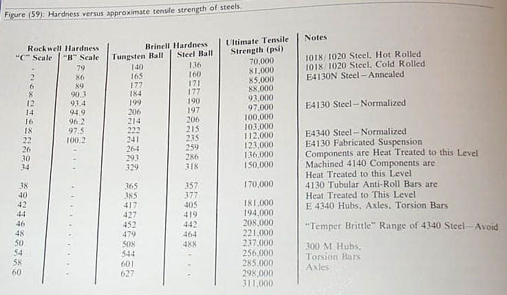
To illustrate the effect of hardening, look at this table, taken from "Engineer To Win". Note, for example, the difference between 4340 at Rockwell C 22 and 4340 at Rockwell C 44!
I will leave the topic here by repeating the golden rule of heat treatment, and the providing a table of some more heat treatment terms: "Heat treatment is the key to a steel parts strength and suitability - but it must be: matched carefully to the alloy, precisely selected for the desired results (properties achieved), and controlled carefully by an expert"
Section 7 - Design principlescoming soon !! This section will be added at a later date and will include discussion on the flow of stress, how removing material can increase strength, how shapes are strong, etc. For now, dig this: Modes of Failure There are only 3 ways that steel parts can break. That is, there are only 3 ways that the atomic bonds of the steel's crystal lattice structure can be broke. They are: tension, compression, and shear. Tension is the action of pulling. Steel parts can be pulled apart - for example, if you grasped 2 ends of a steel bar and pulled lengthwise till is pulled apart like taffy - it would have failed in tension. Compression is the action of being pressed on. We don't generally see steel 4x4 parts failing in compression, but it can still affect us. A more obvious example of compression failure might be a concrete block that is loaded with weight until it crumbles into dust. Now ask yourself - how many rigs have I seen in driveways jacked up on stacks of concrete building blocks? Shear is the action of slicing or cutting through something. Take 2 pieces of steel plate and bolt them together through a hole drilled in each. Now, slide the 2 pieces away from each other in opposite directions and if the bolt fails by getting sliced in half, it has failed in shear. UTS or Ultimate Tensile Strengths for different materials or components are readily published, as they are comparatively easy to determine by testing. A sample is placed into a machine and pulled until it comes apart, the force required is recorded. Compressive strengths are not commonly published, but they are available. Shear strengths for steel products are generally regarded to lie in the range of 60-80% of the UTS of the material. There may seem to be other modes by which a part can fail, but on examination these are really just some combination of the above 3 modes of failure. For example, bending is really just a part that is experiencing tension on one side and compression on the other. Torsional loading is really a combination of tension, compression, and shear all at once (and is therefore fairly complicated to calculate)
Section 8 - Fatiguecoming soon !! This section will be added at a later date and will include discussion on fatigue properties of steel. For now, I will whet your appetite with these scans from the Machinery's Handbook (click on the thumbnail for larger version), no doubt breaking half a dozen international copyright laws. If you are a copyright holder whom I have infringed and you object, please contact me and I will remove the offending material. |
||||||||||||||||||||||||||||||||||||||||||||||||||||||||||||||||||||||||||||||||||||||||||||||||||||||||||||||||||||||||||||||||||||||||||||||||||||||||||||||||||||||||||||||||||||||||||||||||||||||||||||||||||||||||||||||||||||||||||||||||||||||||||||||||||||||||||||||||||||||||||||||||||||||||||||||||||||||||||||||||||||||||||||||||||||||||||||||||||||||||||||||||||||||||||||||||||||||||||||||||||||||||||||||||||||||||||||||||||||||||||||||||||||||||||||||||||||||||||||||||||||||||||||||||||||||||||||||||||||||||||||||||||||||||||||||||||||||||||||||||||||||||||||||||||||||||||||||||||||||||||||||||||||||||||||||||||||||||||||||||||||||||||||||||||||||||||||||||||||||||||||||||||||||||||||||||||||||||||||||||||||||||||||||||||||||||||||||||||||||||||||||||||||||||||||||||||||||||||||||||||||||||||||||||||||||||||||||||||||||||||||||||||||||||||||||||||||||||||||||||||||||||||||||||||||||||
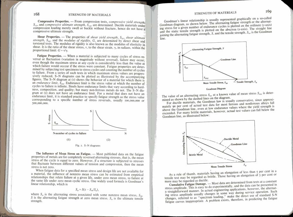 |
Fatigue Properties S-N diagrams Influence of Mean Stress on Fatigue Goodman's Diagram Cumulative fatigue Damage |
|||||||||||||||||||||||||||||||||||||||||||||||||||||||||||||||||||||||||||||||||||||||||||||||||||||||||||||||||||||||||||||||||||||||||||||||||||||||||||||||||||||||||||||||||||||||||||||||||||||||||||||||||||||||||||||||||||||||||||||||||||||||||||||||||||||||||||||||||||||||||||||||||||||||||||||||||||||||||||||||||||||||||||||||||||||||||||||||||||||||||||||||||||||||||||||||||||||||||||||||||||||||||||||||||||||||||||||||||||||||||||||||||||||||||||||||||||||||||||||||||||||||||||||||||||||||||||||||||||||||||||||||||||||||||||||||||||||||||||||||||||||||||||||||||||||||||||||||||||||||||||||||||||||||||||||||||||||||||||||||||||||||||||||||||||||||||||||||||||||||||||||||||||||||||||||||||||||||||||||||||||||||||||||||||||||||||||||||||||||||||||||||||||||||||||||||||||||||||||||||||||||||||||||||||||||||||||||||||||||||||||||||||||||||||||||||||||||||||||||||||||||||||||||||||||||||
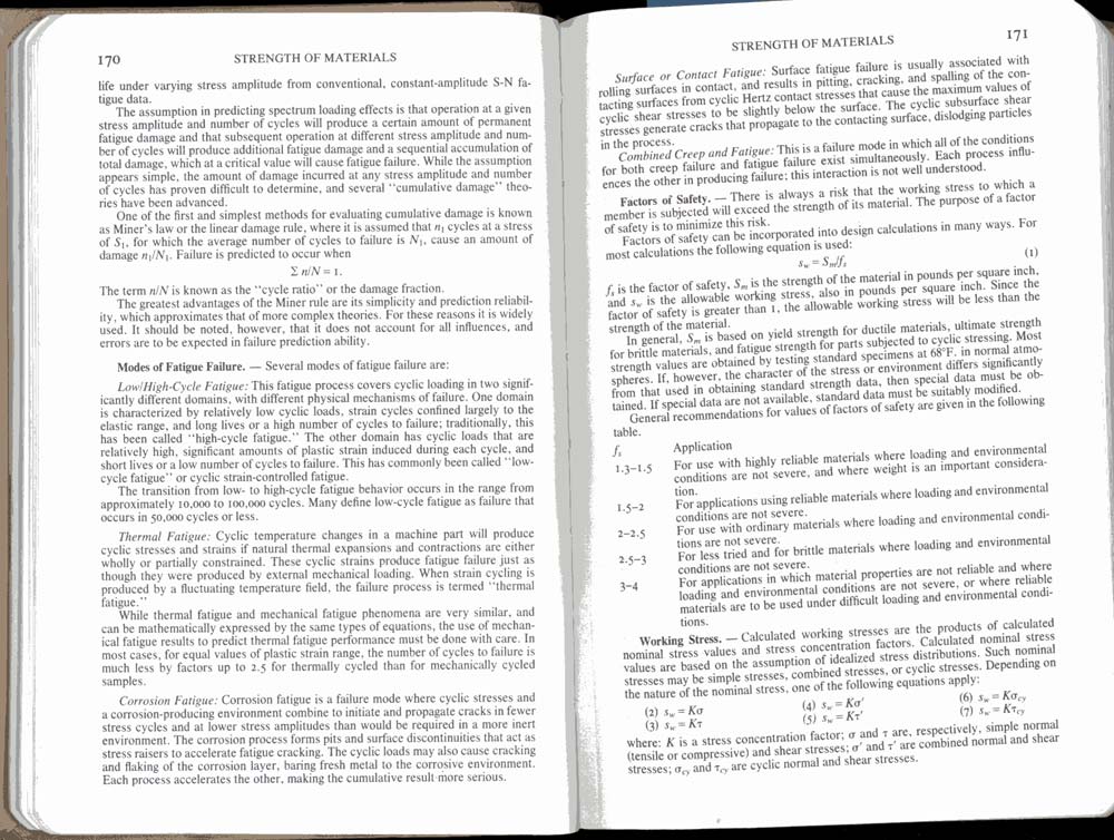 |
Modes of fatigue failure
Factors of Safety (Design Factors) Working Stress |
|||||||||||||||||||||||||||||||||||||||||||||||||||||||||||||||||||||||||||||||||||||||||||||||||||||||||||||||||||||||||||||||||||||||||||||||||||||||||||||||||||||||||||||||||||||||||||||||||||||||||||||||||||||||||||||||||||||||||||||||||||||||||||||||||||||||||||||||||||||||||||||||||||||||||||||||||||||||||||||||||||||||||||||||||||||||||||||||||||||||||||||||||||||||||||||||||||||||||||||||||||||||||||||||||||||||||||||||||||||||||||||||||||||||||||||||||||||||||||||||||||||||||||||||||||||||||||||||||||||||||||||||||||||||||||||||||||||||||||||||||||||||||||||||||||||||||||||||||||||||||||||||||||||||||||||||||||||||||||||||||||||||||||||||||||||||||||||||||||||||||||||||||||||||||||||||||||||||||||||||||||||||||||||||||||||||||||||||||||||||||||||||||||||||||||||||||||||||||||||||||||||||||||||||||||||||||||||||||||||||||||||||||||||||||||||||||||||||||||||||||||||||||||||||||||||||
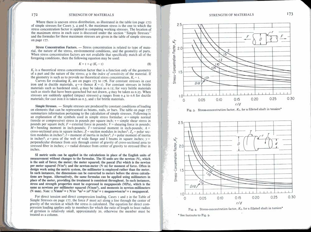 |
Stress concentration Factors Simple Stresses Diagram - Stress-concentration factor for a fillited shaft in tension Diagram - Stress-concentration factor for a fillited shaft in torsion |
|||||||||||||||||||||||||||||||||||||||||||||||||||||||||||||||||||||||||||||||||||||||||||||||||||||||||||||||||||||||||||||||||||||||||||||||||||||||||||||||||||||||||||||||||||||||||||||||||||||||||||||||||||||||||||||||||||||||||||||||||||||||||||||||||||||||||||||||||||||||||||||||||||||||||||||||||||||||||||||||||||||||||||||||||||||||||||||||||||||||||||||||||||||||||||||||||||||||||||||||||||||||||||||||||||||||||||||||||||||||||||||||||||||||||||||||||||||||||||||||||||||||||||||||||||||||||||||||||||||||||||||||||||||||||||||||||||||||||||||||||||||||||||||||||||||||||||||||||||||||||||||||||||||||||||||||||||||||||||||||||||||||||||||||||||||||||||||||||||||||||||||||||||||||||||||||||||||||||||||||||||||||||||||||||||||||||||||||||||||||||||||||||||||||||||||||||||||||||||||||||||||||||||||||||||||||||||||||||||||||||||||||||||||||||||||||||||||||||||||||||||||||||||||||||||||||
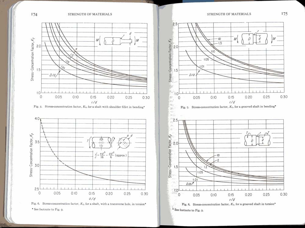 |
Diagram - Stress-concentration factor for a shaft with shoulder fillet in bending Diagram - Stress-concentration factor for a shaft with a transverse hole, in torsion Diagram - Stress-concentration factor for a grooved shaft in bending Diagram - Stress-concentration factor for a grooved shaft in torsion |
|||||||||||||||||||||||||||||||||||||||||||||||||||||||||||||||||||||||||||||||||||||||||||||||||||||||||||||||||||||||||||||||||||||||||||||||||||||||||||||||||||||||||||||||||||||||||||||||||||||||||||||||||||||||||||||||||||||||||||||||||||||||||||||||||||||||||||||||||||||||||||||||||||||||||||||||||||||||||||||||||||||||||||||||||||||||||||||||||||||||||||||||||||||||||||||||||||||||||||||||||||||||||||||||||||||||||||||||||||||||||||||||||||||||||||||||||||||||||||||||||||||||||||||||||||||||||||||||||||||||||||||||||||||||||||||||||||||||||||||||||||||||||||||||||||||||||||||||||||||||||||||||||||||||||||||||||||||||||||||||||||||||||||||||||||||||||||||||||||||||||||||||||||||||||||||||||||||||||||||||||||||||||||||||||||||||||||||||||||||||||||||||||||||||||||||||||||||||||||||||||||||||||||||||||||||||||||||||||||||||||||||||||||||||||||||||||||||||||||||||||||||||||||||||||||||||
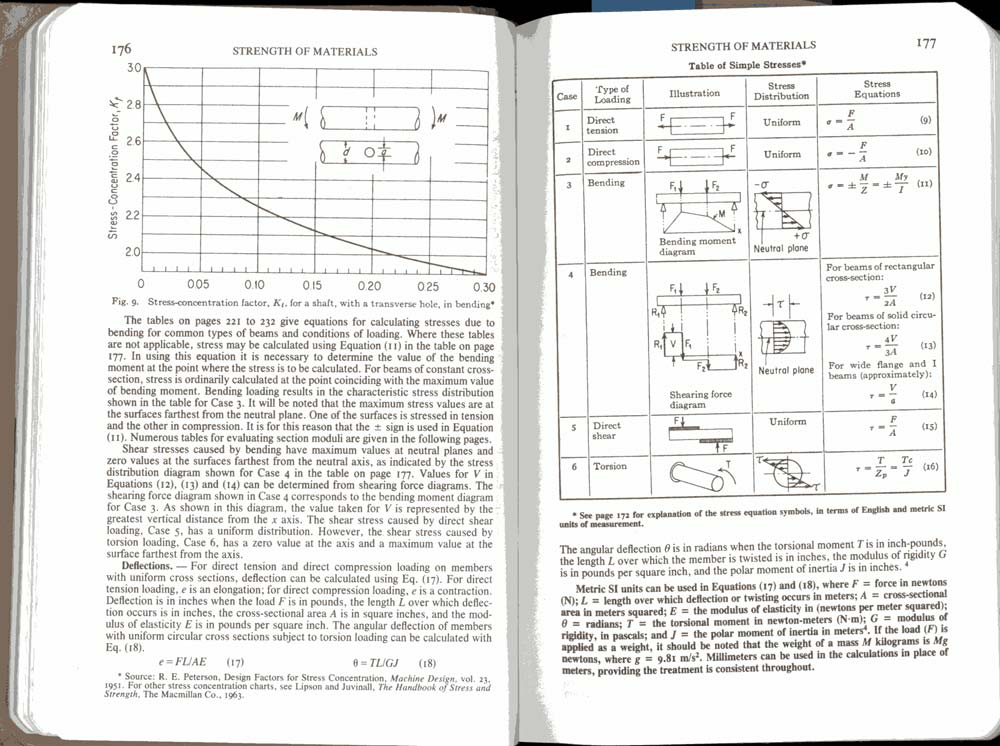 |
Diagram - Stress-concentration factor for a shaft with a transverse hole in bending Deflections Table of Simple Stresses (including shaft in torsion) |
|||||||||||||||||||||||||||||||||||||||||||||||||||||||||||||||||||||||||||||||||||||||||||||||||||||||||||||||||||||||||||||||||||||||||||||||||||||||||||||||||||||||||||||||||||||||||||||||||||||||||||||||||||||||||||||||||||||||||||||||||||||||||||||||||||||||||||||||||||||||||||||||||||||||||||||||||||||||||||||||||||||||||||||||||||||||||||||||||||||||||||||||||||||||||||||||||||||||||||||||||||||||||||||||||||||||||||||||||||||||||||||||||||||||||||||||||||||||||||||||||||||||||||||||||||||||||||||||||||||||||||||||||||||||||||||||||||||||||||||||||||||||||||||||||||||||||||||||||||||||||||||||||||||||||||||||||||||||||||||||||||||||||||||||||||||||||||||||||||||||||||||||||||||||||||||||||||||||||||||||||||||||||||||||||||||||||||||||||||||||||||||||||||||||||||||||||||||||||||||||||||||||||||||||||||||||||||||||||||||||||||||||||||||||||||||||||||||||||||||||||||||||||||||||||||||||
Section 9 - Dispelling myths / FAQThis section is a sort of practical summary of all the knowledge contained in this article. It will address several common myths and also serve as a FAQ. It will hopefully be periodically updated and amended as required. Ultimately I hope it contains not only the answers to the myths and frequently asked questions, but also the reasoning. In the interim, however, it may just contain blunt answers and the reader will have to return to the theory in the article and make the connections themselves. Q: Which is stronger in torsion - a hollow or solid shaft of the same size (OD)? A: Solid. However, depending how much material is removed from the middle of the hollow shaft (i.e. how thick the walls remain) often the hollow shaft saves significant weight while sacrificing VERY LITTLE strength. However, the solid shaft WILL ALWAYS ultimately be stronger, just sometimes not by very much. The following offers proof: |
||||||||||||||||||||||||||||||||||||||||||||||||||||||||||||||||||||||||||||||||||||||||||||||||||||||||||||||||||||||||||||||||||||||||||||||||||||||||||||||||||||||||||||||||||||||||||||||||||||||||||||||||||||||||||||||||||||||||||||||||||||||||||||||||||||||||||||||||||||||||||||||||||||||||||||||||||||||||||||||||||||||||||||||||||||||||||||||||||||||||||||||||||||||||||||||||||||||||||||||||||||||||||||||||||||||||||||||||||||||||||||||||||||||||||||||||||||||||||||||||||||||||||||||||||||||||||||||||||||||||||||||||||||||||||||||||||||||||||||||||||||||||||||||||||||||||||||||||||||||||||||||||||||||||||||||||||||||||||||||||||||||||||||||||||||||||||||||||||||||||||||||||||||||||||||||||||||||||||||||||||||||||||||||||||||||||||||||||||||||||||||||||||||||||||||||||||||||||||||||||||||||||||||||||||||||||||||||||||||||||||||||||||||||||||||||||||||||||||||||||||||||||||||||||||||||||
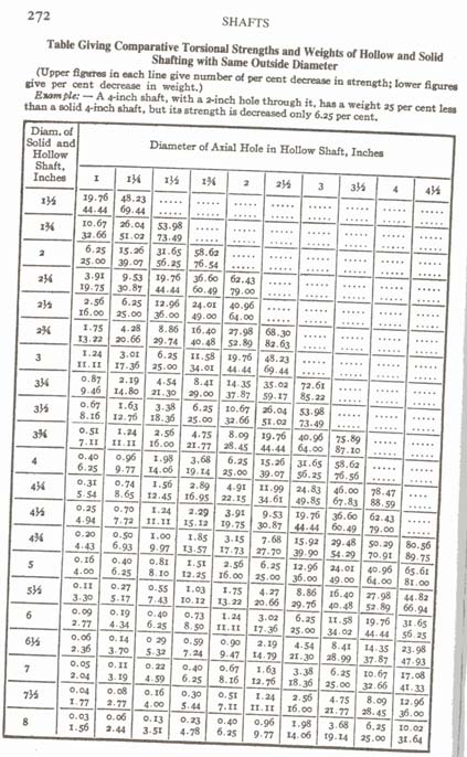 |
Table giving Comparative Torsional Strengths and weights of Hollow and Solid Shafting with Same Outside Diameter.[12] | |||||||||||||||||||||||||||||||||||||||||||||||||||||||||||||||||||||||||||||||||||||||||||||||||||||||||||||||||||||||||||||||||||||||||||||||||||||||||||||||||||||||||||||||||||||||||||||||||||||||||||||||||||||||||||||||||||||||||||||||||||||||||||||||||||||||||||||||||||||||||||||||||||||||||||||||||||||||||||||||||||||||||||||||||||||||||||||||||||||||||||||||||||||||||||||||||||||||||||||||||||||||||||||||||||||||||||||||||||||||||||||||||||||||||||||||||||||||||||||||||||||||||||||||||||||||||||||||||||||||||||||||||||||||||||||||||||||||||||||||||||||||||||||||||||||||||||||||||||||||||||||||||||||||||||||||||||||||||||||||||||||||||||||||||||||||||||||||||||||||||||||||||||||||||||||||||||||||||||||||||||||||||||||||||||||||||||||||||||||||||||||||||||||||||||||||||||||||||||||||||||||||||||||||||||||||||||||||||||||||||||||||||||||||||||||||||||||||||||||||||||||||||||||||||||||||
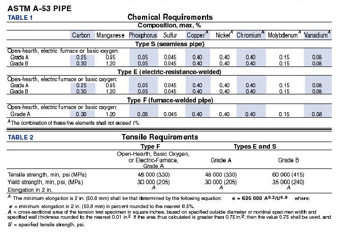
Q: What should I use for my cage/bumper/tube chasis/whatever - HREW, DOM, or Cr-Mo? A: Depends on your budget, needs, and ability to weld and stress relieve. 1020 DOM is an excellent all-around choice for most - clean, tight tolerances, good strength, reasonable cost, and fairly readily bent and welded. HREW is a good low-cost, easy to work with alternative for non-critical applications or mild use. Cr-Mo is the top of the strength scale (depending on condition, of course) but with some serious drawbacks: Unless properly TIG of Oxy-Acetylene welded AND properly post-weld stress-relieved all you have is an expensive pile of tubing no stronger than 1020 DOM (all you Cr-Mo MIG welders take note!!). It is also expensive and a bear to bend, cut, drill, and machine. Q: Is pipe only for plumbing? A: Certainly not. In fact, the word "pipe" is often grossly misused. It is, of course, not a designation of any particular product or material, and therefore confers no meaning in terms of any particular mechanical properties (strength, ductility, impact resistance, etc.) Pipe is a type of steel tube, usually intended to convey liquid or gas. I say usually because, in the construction industry, material labelled "pipe" is frequently used in the construction of bridges, buildings, oil rigs etc. Pipe, like any steel tube comes in various grades and conditions - some quite suitable for building 4x4 parts, and some not at all - just like other steel products. You have to know what you're dealing with, what its condition is, and what its properties are before you can decide. Here is some comparative data on one common type of pipe, though again, it is in no way representative of all "pipe" The ASTM A-53 spec is the American Society for Testing and Materials specification that covers seamless and welded steel pipe intended for mechanical and pressure applications, including ordinary uses in steam, water, gas, and air lines. Note that it says "mechanical applications" whcih means building things. Also note that the yield strength of this most common type of pipe is 30,000-35,000 compared to 32,000-40,000 psi for common 1010 ERW, CREW, and HREW compared to 70,000 psi for 1020 DOM and 90,000 psi for 4130 Cr-Mo DOM.
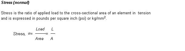
Q: What's the difference in how tube and pipe are called-out (described) in terms of dimension (size)? A: Round steel mechanical tubing ("tube") is called out by either a specified OD and wall thickness (with resulting ID) or in other cases by specifying both an OD and ID (and getting a resulting wall thickness). In practical terms these amount to the same thing and you usually order steel tubing by asking for an OD and wall thickness. Pipe is slightly more complicated: The document: "Wrought Steel Pipe - ANSIB36.10-1979" covers dimensions of welded and seamless wrought steel pipe, for high or low temperatures or pressures. The word "pipe" as distinguished from "tube" is used to apply to tubular products of dimensions commonly used for pipelines and piping systems. Pipe dimensions of sizes 12 inches and smaller have outside diameters numerically larger than the corresponding nominal sizes whereas outside diameters of tubes are identical to nominal sizes. The size of all pipe is identified by the nominal pipe size. The manufacture of pipe in the nominal size of 1/8" to 12" inclusive, is based on a standardized outside diameter. This OD was originally selected so that pipe with a standard OD and having a wall thickness which was typical of the period would have an inside diameter approximately equal to the nominal size. Although there is now no such relation between the existing standard thicknesses, ODs and nominal sizes, these nominal sizes and standard ODs continue in use as "standard". Industry publications will list pages of tables of these "standard" dimensions. For example. A 1" pipe will have an OD of 1.315" and a wall thickness depending on its schedule as follows. Schedule 40 - 0.133 there is excellent data available on pipe sizes, dimensions, and weights in the Loucon Steel Catalogue, starting on page 16. Section 10 - Equations:The following equations are provided for the mathematically oriented reader simply for the purpose of understanding and illustrating the concepts discussed in this article: DO NOT USE THEM for calculations, as they may not include critical elements suchas design factor, impact loads, safety margins, and fatigue factors! (that's what professional Engineers are for :-) Stress:
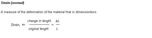
Strain
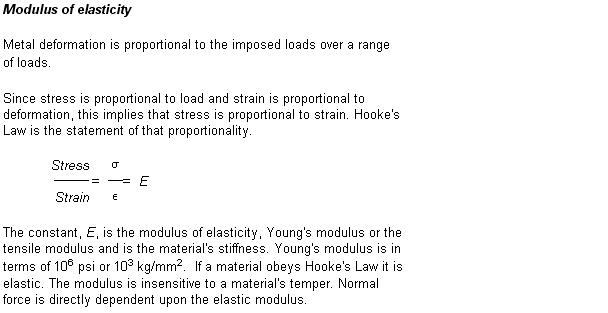
Modulus of Elasticity
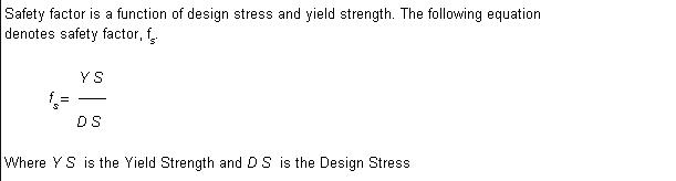
Design (Safety) Factor
Roy McBride and Dave Towers of Heriot Watt University excellent tutorial on Torsion of shafts with circular symmetry an MS Word .doc file. Also available in .pdf format Section 11 - Tables:The following tables present a great deal of information that you may find interesting or of use: Typical Mechanical Properties of round Carbon Steel Tube and Pipe - compares HREW, DOM, Pipe etc. Typical Mechanical Properties of round Alloy Steel Tube - Chrom-moly tube properties Typical Mechanical Properties of Seamless and ERW Pipe - it's not just for poop! Section 12 - Glossary:General Steel and Iron Terms
Section 13 - Sources and Notes:The following are related Steel links
and resources. Iron and Steel Industry - Compton's encyclopedia on the history of iron and steel origins, production and modern industry. Ryerson - supplies industry with more than 100,00 items of steel, stainless steel, aluminium etc. material. Check here for local distributors and stock list. American Steel and Iron Institute - AISI organization. International World Steel Organization - Good general and informational resource. The Engineer's Edge - Engineering data and information Engineering Fundamentals - Engineering data and information (limited free info, pay site) The Steel Tubing Institute of North America - The web site of the folks that make the stuff Seaport Steel Co. - A Steel company with some tech info on their page Thompson Metals and Tubing Co. - Another company with tech info on their pages. Notes: [1] "Engineer to Win". Carroll Smith; Motorbooks International, 1985 p.49 [2] "Engineer to Win". Carroll Smith; Motorbooks International, 1985 p.45 [3] "Engineer to Win". Carroll Smith; Motorbooks International, 1985 p.44 [4] "Engineer to Win". Carroll Smith; Motorbooks International, 1985 p.53 [5] "Engineer to Win". Carroll Smith; Motorbooks International, 1985 p.63 [6] "Machinery's Handbook" 24th Edition. Erik Oberg, Franklin D. Jones, Holbrook L. Horton, Henry H. Ryffel, Robert E. Green; Industrial Press Inc., 1992 p.381 [7] "Engineer to Win". Carroll Smith; Motorbooks International, 1985 p.63 [8] "Machinery's Handbook" 24th Edition; "Engineer to Win". Carroll Smith; [9] "Engineer to Win". Carroll Smith; Motorbooks International, 1985 p.60 [10] http://www.steeltubeinstitute.org/dom.htm [11] "Engineer to Win". Carroll Smith; Motorbooks International, 1985 p.62 [12] "Machinery's Handbook" 24th Edition. Erik Oberg, Franklin D. Jones, Holbrook L. Horton, Henry H. Ryffel, Robert E. Green; Industrial Press Inc., 1992 p.272 |
||||||||||||||||||||||||||||||||||||||||||||||||||||||||||||||||||||||||||||||||||||||||||||||||||||||||||||||||||||||||||||||||||||||||||||||||||||||||||||||||||||||||||||||||||||||||||||||||||||||||||||||||||||||||||||||||||||||||||||||||||||||||||||||||||||||||||||||||||||||||||||||||||||||||||||||||||||||||||||||||||||||||||||||||||||||||||||||||||||||||||||||||||||||||||||||||||||||||||||||||||||||||||||||||||||||||||||||||||||||||||||||||||||||||||||||||||||||||||||||||||||||||||||||||||||||||||||||||||||||||||||||||||||||||||||||||||||||||||||||||||||||||||||||||||||||||||||||||||||||||||||||||||||||||||||||||||||||||||||||||||||||||||||||||||||||||||||||||||||||||||||||||||||||||||||||||||||||||||||||||||||||||||||||||||||||||||||||||||||||||||||||||||||||||||||||||||||||||||||||||||||||||||||||||||||||||||||||||||||||||||||||||||||||||||||||||||||||||||||||||||||||||||||||||||||||||
|