 |
Dana 20 Rebuild By Bill "BillaVista" Ansell |
IntroductionWelcome to the second instalment of my ambitious project to build a strong, all-gear, compact, twin-stick, low-geared transfer case at home, bit by bit, as I can afford it - a project I call Uber-20; named for the core component - a '79 Jeep CJ Dana 20 transfer case that lies at the heart of my rock buggy. In this part I upgrade the fairly tame 2.0:1 low range ratio of the Dana 20 to a far more respectable, and useful, 3.15:1 using Teraflex Manufacturing's "Low 20" replacement gear set. Follow along as I detail the why, the how, and the results of my latest upgrade. |
 |
 |
The need for super-low gearing in technical rock crawling and other hardcore wheeling is no secret and no surprise. Long gone are the days when 100:1 overall gearing was considered as deep as anyone would ever need. | ||||||||||||||||||||||||||||||||||||||||||||||||||||||||||||||||||||||||||||||||||||||||||||||||||||||||||||||||||||||||||||||||||||||||||||||||||||||||
 |
More technical courses and more extreme trails demand greater control and that means low gears - in my opinion there really is no "too low", BUT... | ||||||||||||||||||||||||||||||||||||||||||||||||||||||||||||||||||||||||||||||||||||||||||||||||||||||||||||||||||||||||||||||||||||||||||||||||||||||||
...To have a truly capable rig, you need far more than just a super-low low. Especially if you want it to be capable, drivable, and fun over a variety of terrain. Strangely, what, in my opinion, is one of the most important aspects of a 4x4s performance is never talked about. In fact - I've never seen anyone discuss it - the concept only occurred to me because of experience in another sport. Many, many moons ago I used to do a bit of bicycle racing. As you can imagine - gearing and gear choices are extremely important to the cyclist - especially since it's your legs that are providing the power. Just as in building 4x4s, serious cyclists build their own gearing by building custom combinations of sprockets on the front and rear cogs of the bike. Too low or too high a gearing for the combination of bike, rider, and course - and it's almost impossible to win. But cyclist know there's much more to it than that. So here's the secret to not only winning bike racing - but to great 4x4 performance as well - the concept is called "gear stepping". If you've ever ridden a bicycle you are already familiar with the concept. Take, for example, your average 18 speed bicycle - it will have 3 sprockets on the front (crank sprockets) and 6 sprockets on the back (freewheel sprocket) for a total of 3 x 6 = 18 gears. HOWEVER - not all 18 of these gears are useable - the progression from one to the other is not linear. Say you start peddling on the smallest front sprocket and the largest rear sprocket - this is the lowest and easiest gear the bike has. As you pick up speed you shift the rear derailleur through the 6 gears on the rear sprocket. If you were to then shift the rear derailleur back to the largest while simultaneously shifting the front derailleur to the next larger sprocket - you would find that the gear this put you in was not a step higher (harder to peddle) than the last gear you were in - in fact, it would most likely be a step backwards and be a lower gear. This is because of the fixed number of teeth on the sprockets which determines the actual gear ratios available. So this gear ends up being unusable, and the experienced cyclist skips it and goes on to another combination he knows to be a higher gear. In fact, the serious cyclist will calculate out the ratios achieved by each possible combination, including the percentage jump from one to the next. The resulting table looks something like this:
By considering this table, the cyclist can determine which gears are "useable" and which are not, and furthermore, for a given course, will plan which gears to use in which order - a plan in which the percentage jump becomes critical - you don't want to suddenly shift to a gear that is 50% harder as you would lose your momentum and stall. Take particular note of the ratios between 6th gear and 11th gear. Notice that if you were pedalling along in 6th gear (chain on the small front sprocket and smallest freewheel sprocket) and then just shift into 7th gear (chain on large front sprocket and largest freewheel sprocket) it actually gets easier to pedal (gear ratio goes down instead of up) - we've probably all experienced this, and it would spell disaster in a race (in a car race - like downshifting along the straightaway instead of upshifting). Also note, that in order to "upshift" this bike from 6th gear we have to go all the way to 11th gear - making gears 7-10 essentially useless, and leaving our fancy 12 speed bike really an 8 speed. If I was planning to race this bike, having charted the ratios, I would know my planned shift pattern would have to be 1-2-3-4-5-6-11-12. GUESS WHAT?! ALL of these concepts apply equally well to the 4x4. With multi-speed transmission and one or more 2 speed transfer-cases we have a wide array of gear choices, often spread all over the place. The thing is, we often talk only of our lowest gear and seldom, if ever, does anyone chart their whole range of possible gear ratios and which are useable (and in what order). Well, before I decided to upgrade my T-cases gear set, I did just that, and then re-did it with the numbers from the Tera Low kit. The results were dramatic, to say the least - and convinced me that this was the right route to go - even over changing to an aftermarket transfer case. Here are my available gears before the Tera Low upgrade:
(The Wolf's axle ratio of 4.1:1 is not shown because it is consistent for all cases, though it is included in the calculation of the final ratio; in addition, both the NP 203 and D20 high (H) and low (L) ratios are 1:1 and 2:1 respectively, and the SM 465 gears are: 1 - 6.55, 2 - 3.58, 3 - 1.57 4 - 1.00) Note that 4 of the gears are completely wasted since the low ratios of the 2 transfer cases in the Wolf are the same. Note also that 26:1 and 27:1 are so close as to be indistinguishable, as are 15:1, and 16:1, so if we delete those, we are left with only the following final ratios:
Looking at this table, a couple of things should become immediately apparent: 1) There are still "unusable",
or at least "indistinguishable" gear ratios - experience tells
me anything less than about a 2) On the other side of the coin, there are some HUGELY wide ratio jumps - from 59:1 to 107:1 for example, (an 81% jump) - leaving a big gap in drivability - which can not only kill performance over a variety of terrain (especially as it changes from gnarly obstacle to mixed trail to easy spots - as most trails do), but can also make the rig a pain in the a$$ to drive. The beauty of upgrading the guts of my T-case with the Low 20 kit is that it not only significantly improves my overall lowest low, but also has a huge effect on these two problem areas. Results coming at the end of the article. Dana 20 Teardown |
|||||||||||||||||||||||||||||||||||||||||||||||||||||||||||||||||||||||||||||||||||||||||||||||||||||||||||||||||||||||||||||||||||||||||||||||||||||||||
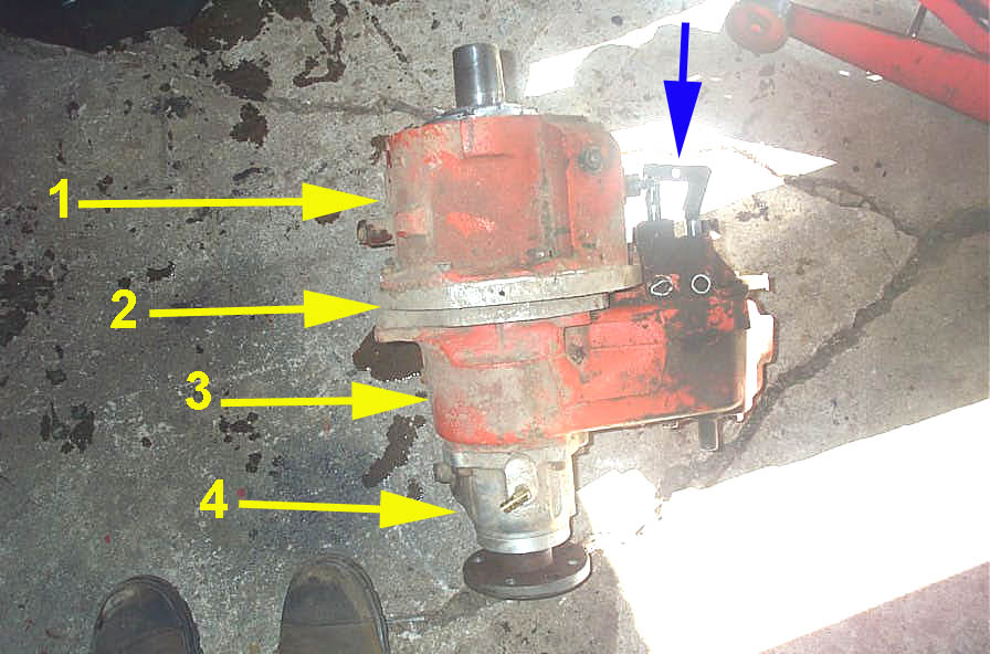 |
You're on your own for removing the Dana 20 from your vehicle, as there are endless possible configurations. For example, here you can see my custom transfer case doubler removed from the Wolf and consisting of:
For orientation, the blue arrow in the pic indicates the shift rods of the Dana 20. |
||||||||||||||||||||||||||||||||||||||||||||||||||||||||||||||||||||||||||||||||||||||||||||||||||||||||||||||||||||||||||||||||||||||||||||||||||||||||
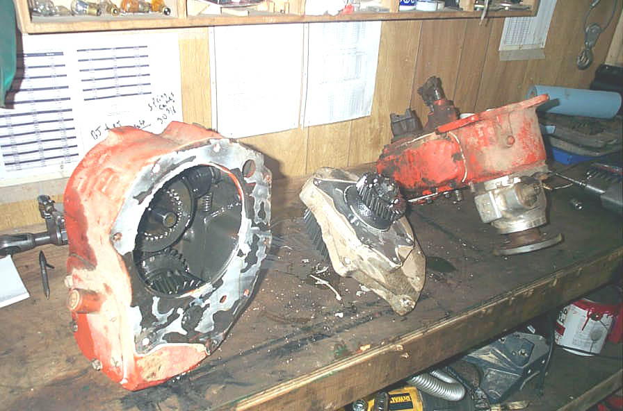 |
In my case, the first task was to separate the Dana 20 from the rest of the transfer case components. From left to right we can see the NP 203 low range box, the doubler adapter, and the separated Dana 20. | ||||||||||||||||||||||||||||||||||||||||||||||||||||||||||||||||||||||||||||||||||||||||||||||||||||||||||||||||||||||||||||||||||||||||||||||||||||||||
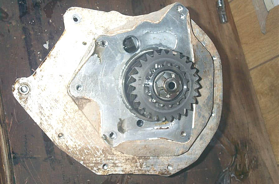 |
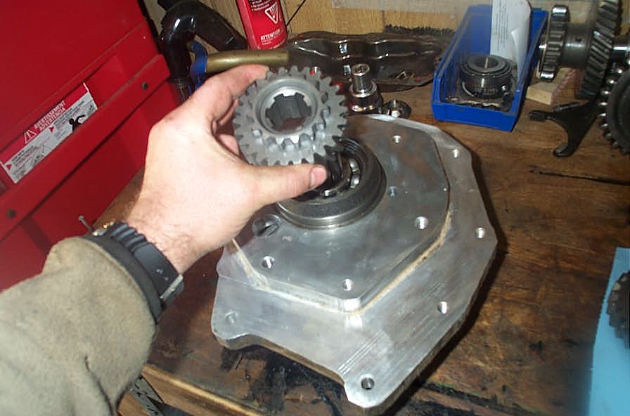
This shot shows the Dana 20 input gear attached to the doubler adapter via the output shaft of the custom machined (shortened and re-splined) 203 output shaft. In non-doubler installations, this D20 input gear will be on the transmission's output shaft. |
||||||||||||||||||||||||||||||||||||||||||||||||||||||||||||||||||||||||||||||||||||||||||||||||||||||||||||||||||||||||||||||||||||||||||||||||||||||||
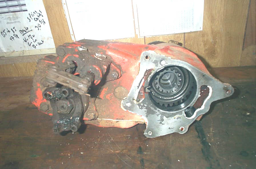 |
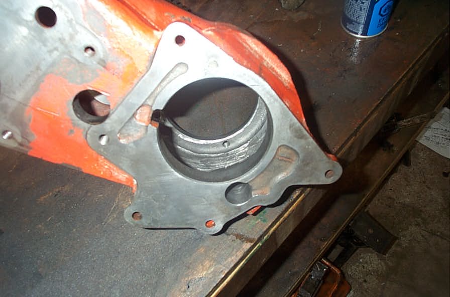
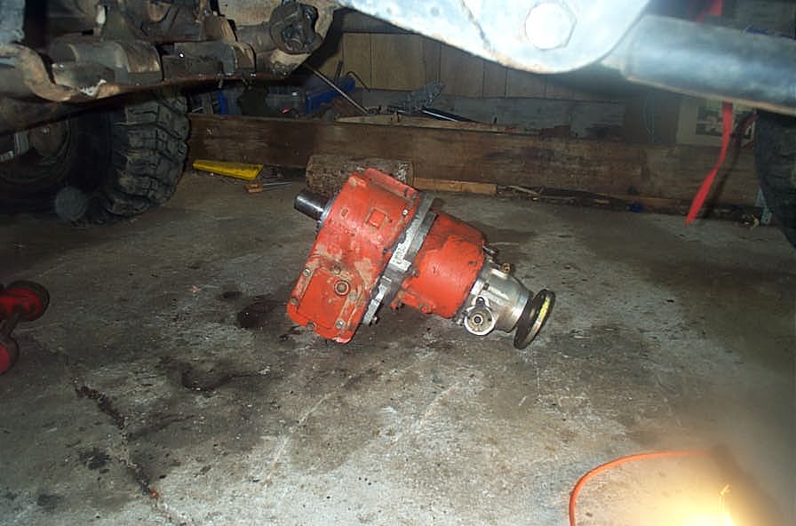
Front view of the removed Dana 20. | ||||||||||||||||||||||||||||||||||||||||||||||||||||||||||||||||||||||||||||||||||||||||||||||||||||||||||||||||||||||||||||||||||||||||||||||||||||||||
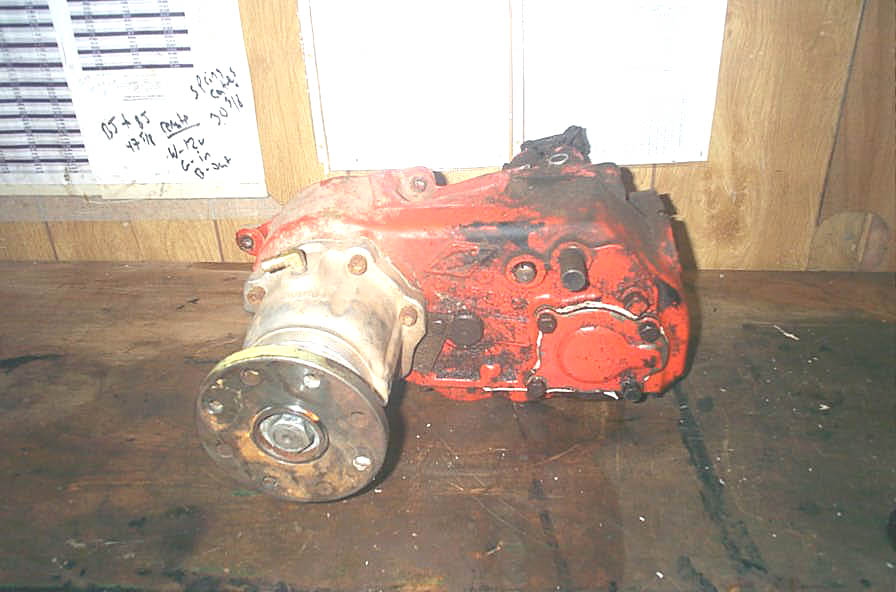 |
Rear view of the Dana 20. | ||||||||||||||||||||||||||||||||||||||||||||||||||||||||||||||||||||||||||||||||||||||||||||||||||||||||||||||||||||||||||||||||||||||||||||||||||||||||
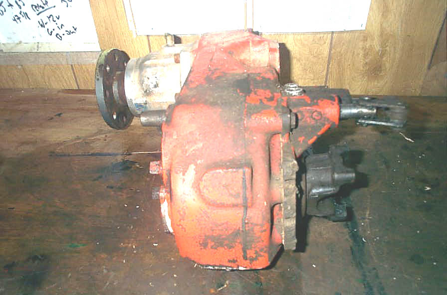 |
Right side view of the Dana 20. | ||||||||||||||||||||||||||||||||||||||||||||||||||||||||||||||||||||||||||||||||||||||||||||||||||||||||||||||||||||||||||||||||||||||||||||||||||||||||
 |
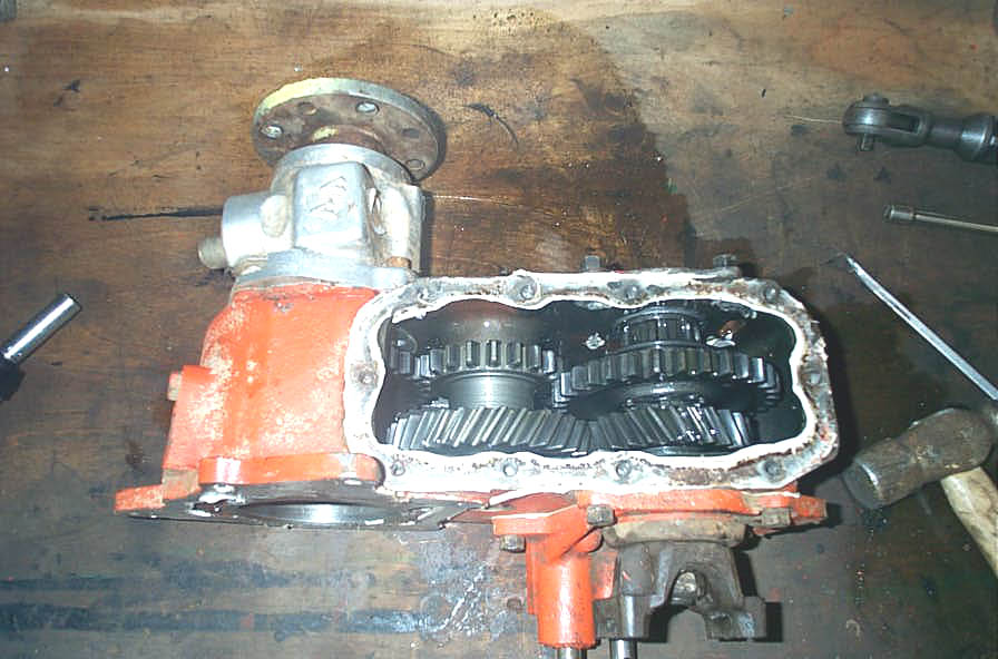
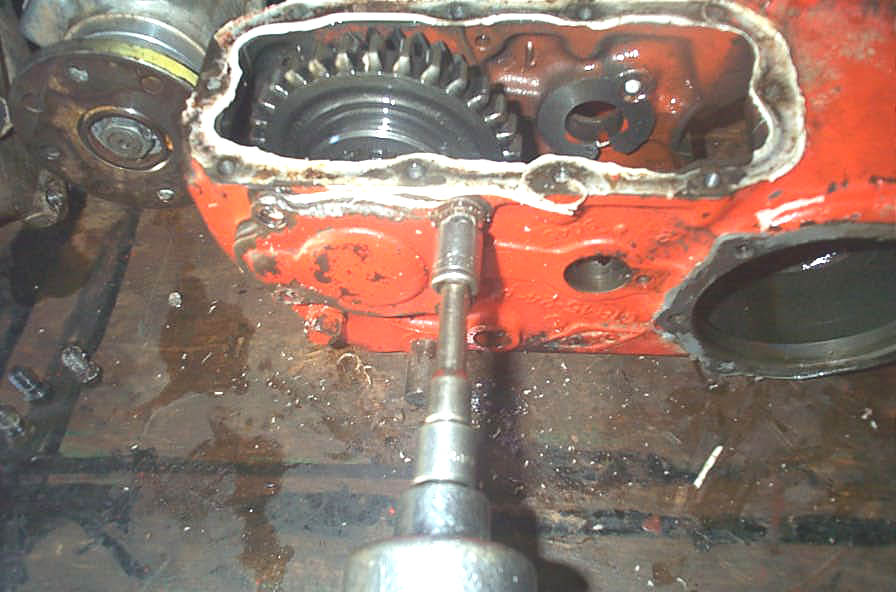
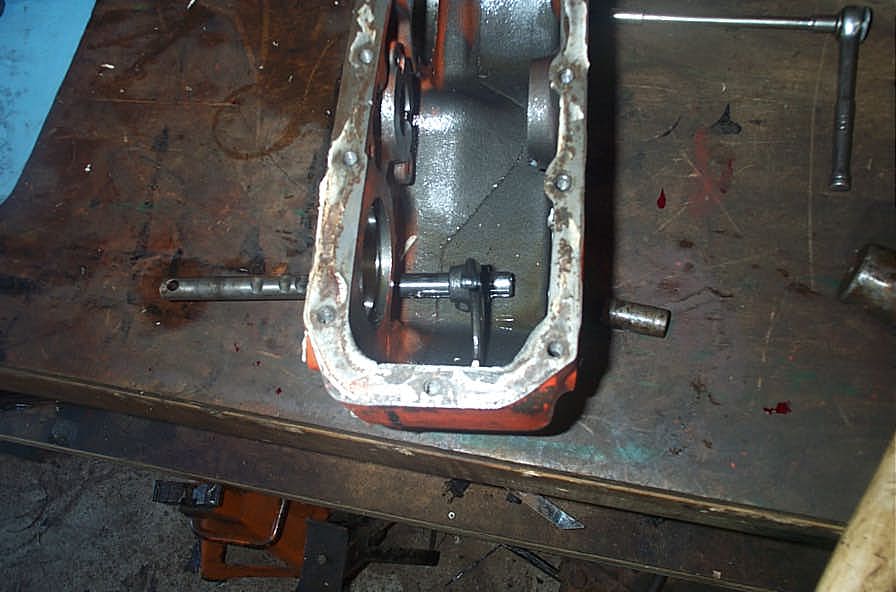
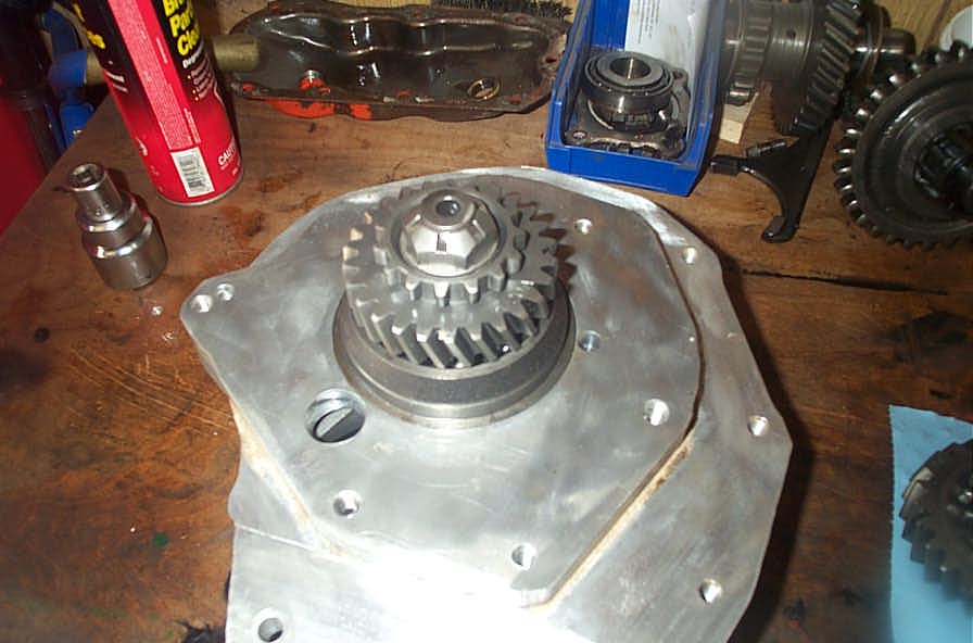
To begin the teardown of the transfer case, place it on a sturdy bench, upside down with the lower cover facing up, as shown here. | ||||||||||||||||||||||||||||||||||||||||||||||||||||||||||||||||||||||||||||||||||||||||||||||||||||||||||||||||||||||||||||||||||||||||||||||||||||||||
 |
Begin by removing the bolts that hold on the lower cover... | ||||||||||||||||||||||||||||||||||||||||||||||||||||||||||||||||||||||||||||||||||||||||||||||||||||||||||||||||||||||||||||||||||||||||||||||||||||||||
 |
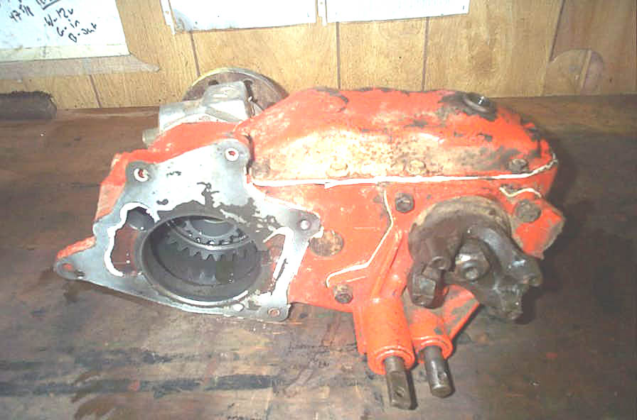
...and remove the lower cover. | ||||||||||||||||||||||||||||||||||||||||||||||||||||||||||||||||||||||||||||||||||||||||||||||||||||||||||||||||||||||||||||||||||||||||||||||||||||||||
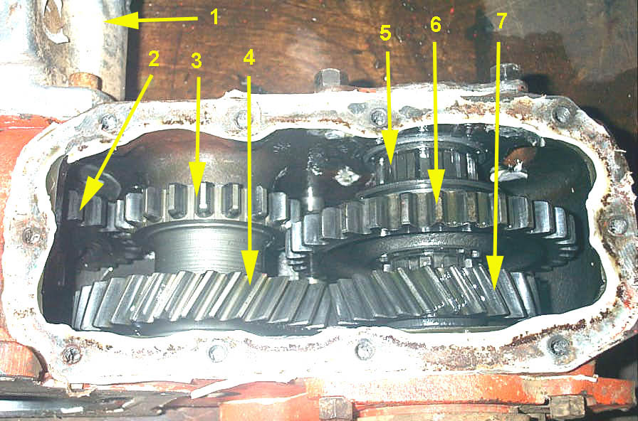 |
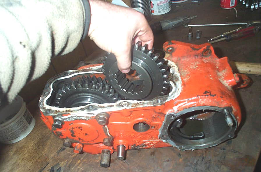
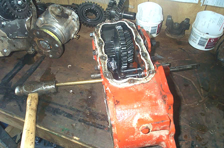
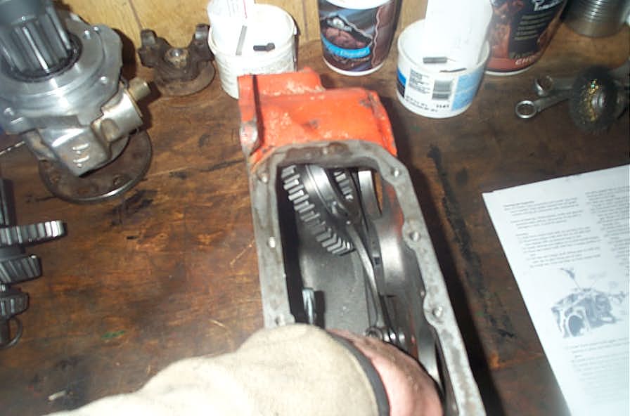
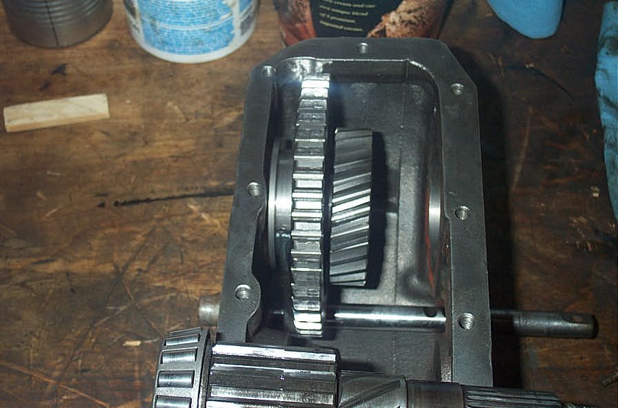
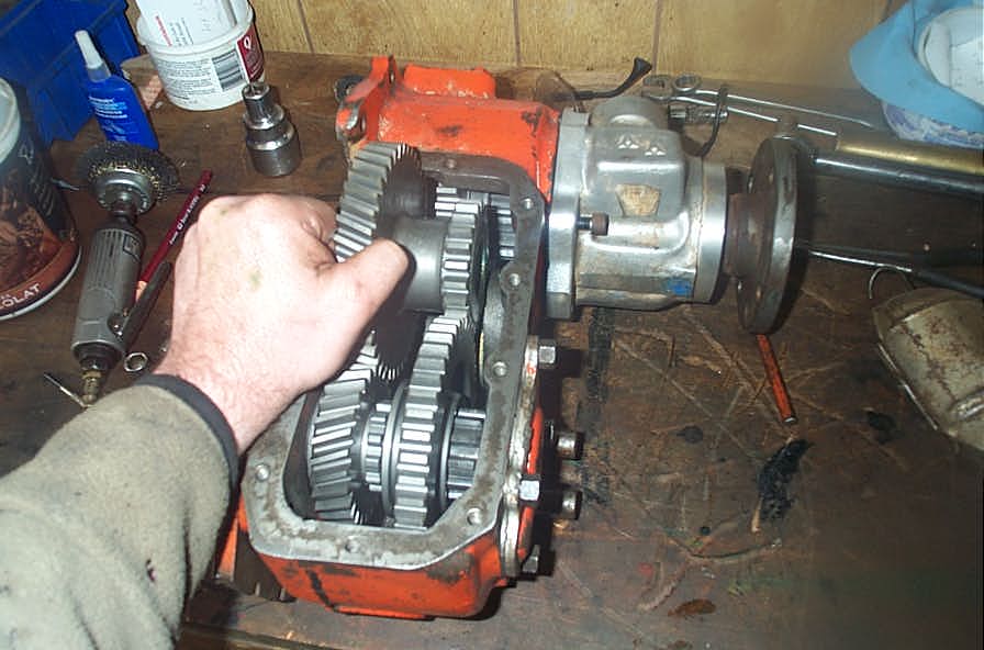
Inside the stock Dana 20 we have:
*not shown in this view is the main drive gear (input gear) which is still attached to the doubler adapter at this point (see above) |
||||||||||||||||||||||||||||||||||||||||||||||||||||||||||||||||||||||||||||||||||||||||||||||||||||||||||||||||||||||||||||||||||||||||||||||||||||||||
 |
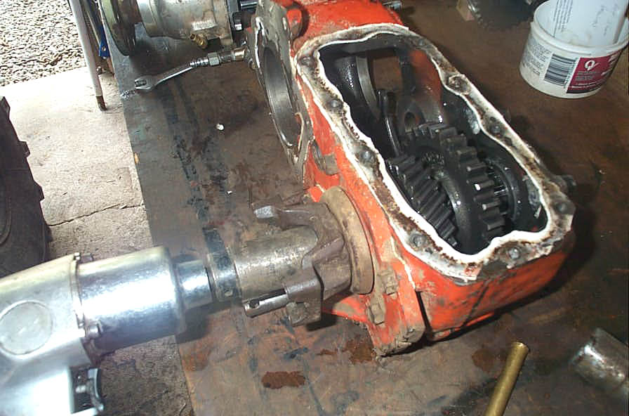
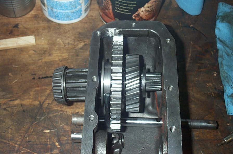
As above, from greater distance | ||||||||||||||||||||||||||||||||||||||||||||||||||||||||||||||||||||||||||||||||||||||||||||||||||||||||||||||||||||||||||||||||||||||||||||||||||||||||
 |
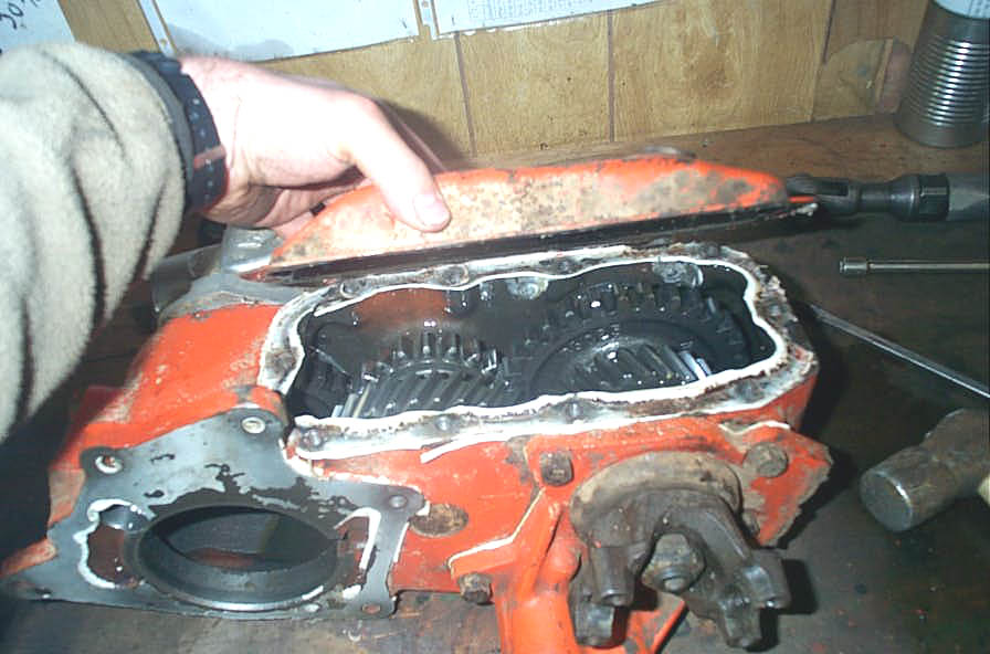
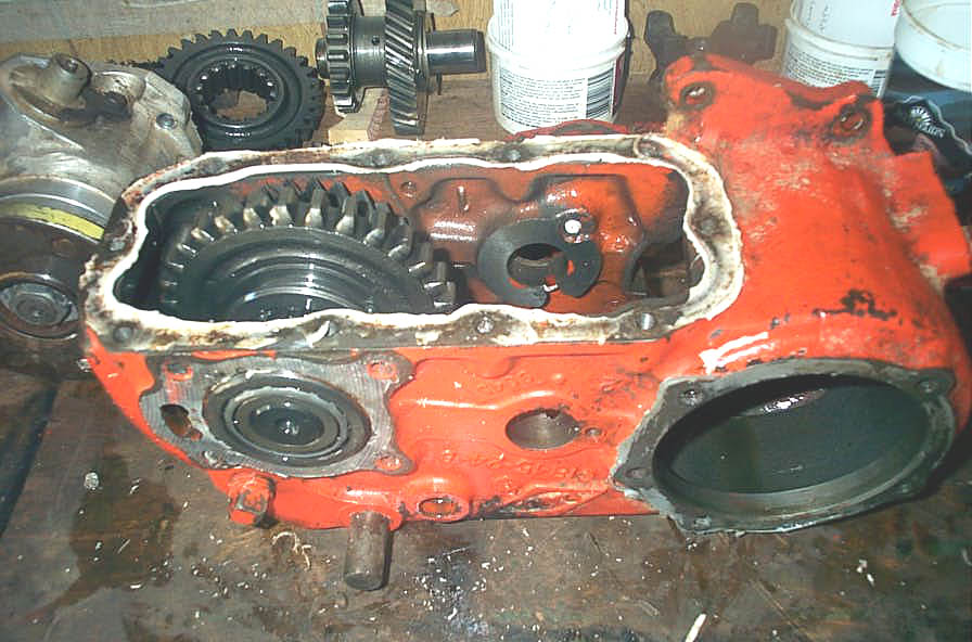
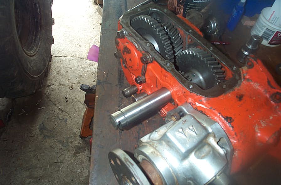
Remove rear output shaft housing assembly. Procedure is similar whether output housing is stock or aftermarket. | ||||||||||||||||||||||||||||||||||||||||||||||||||||||||||||||||||||||||||||||||||||||||||||||||||||||||||||||||||||||||||||||||||||||||||||||||||||||||
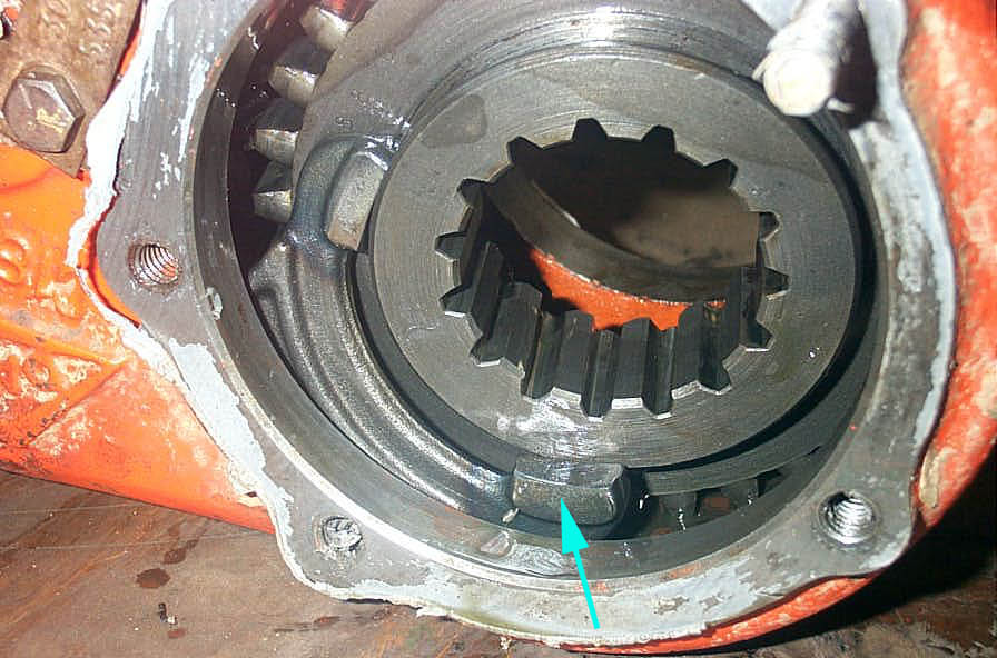 |
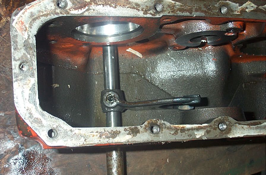
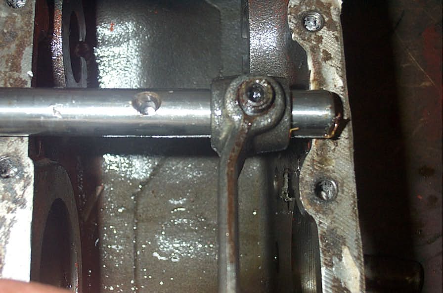
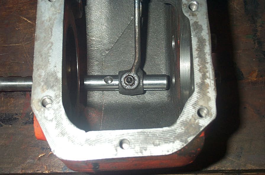
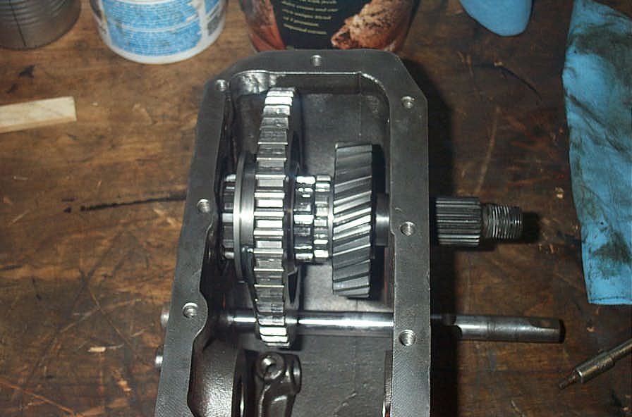
Once the rear output shaft assembly is removed, disconnect the rear sliding gear from the jaws of the rear shift fork (blue arrow). | ||||||||||||||||||||||||||||||||||||||||||||||||||||||||||||||||||||||||||||||||||||||||||||||||||||||||||||||||||||||||||||||||||||||||||||||||||||||||
 |
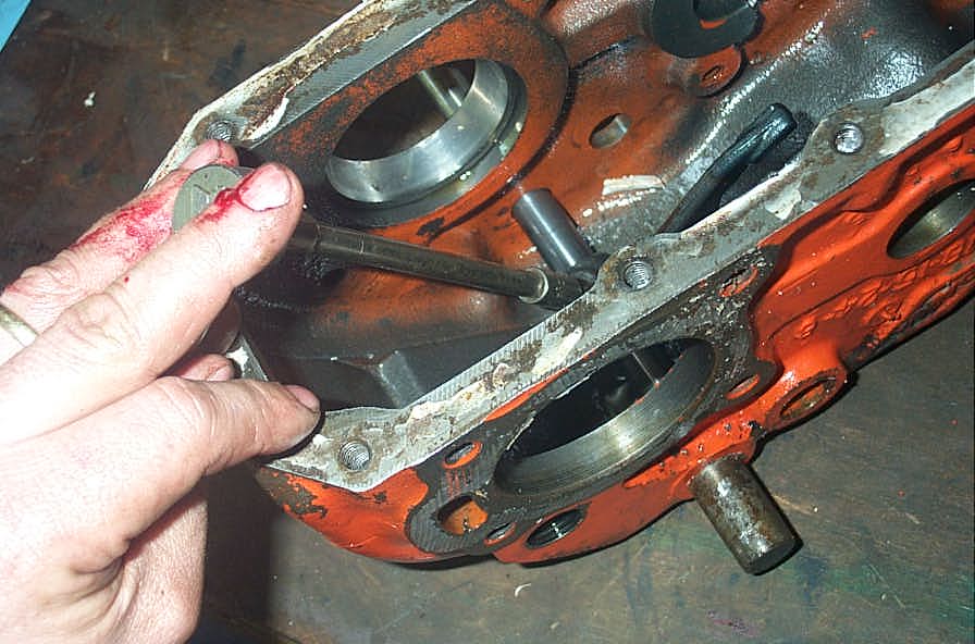
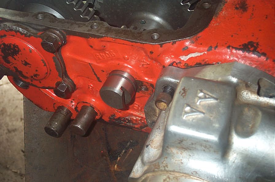
Next,on the front of the case, remove the transfer cases tag (if it's still present) and the lock plate for the intermediate shaft. | ||||||||||||||||||||||||||||||||||||||||||||||||||||||||||||||||||||||||||||||||||||||||||||||||||||||||||||||||||||||||||||||||||||||||||||||||||||||||
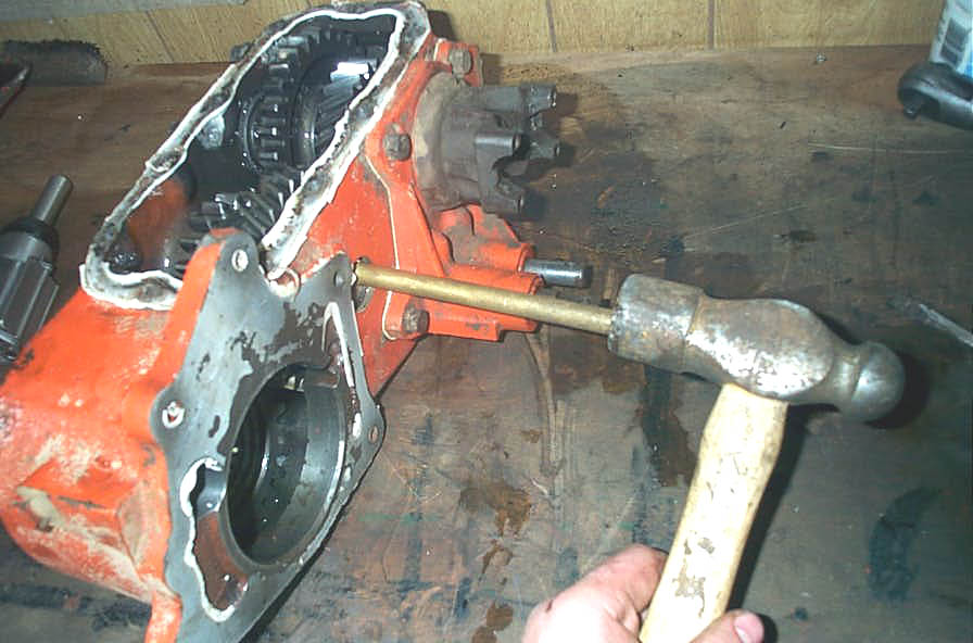 |
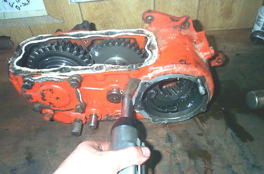
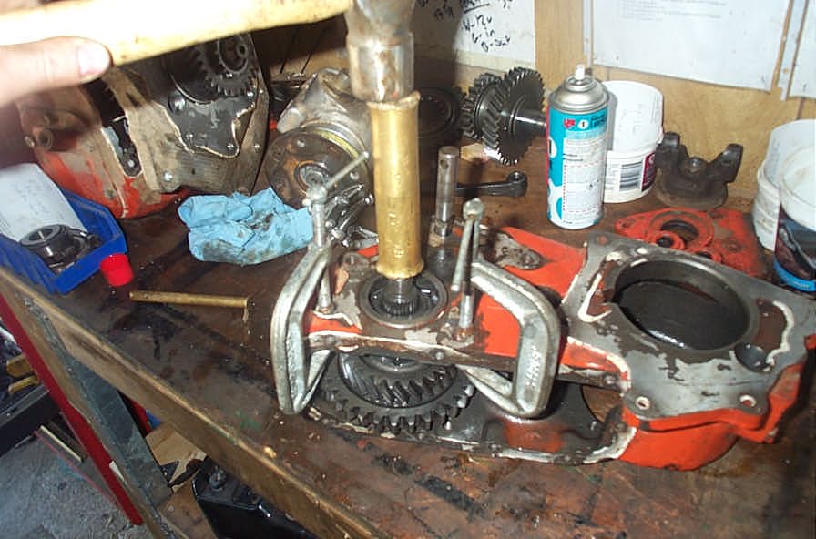
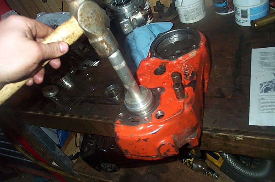
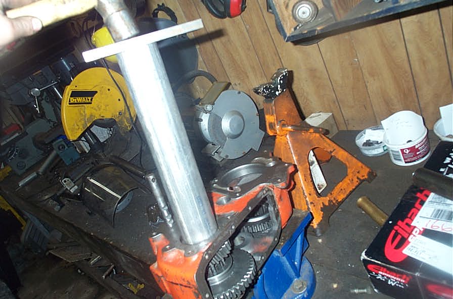
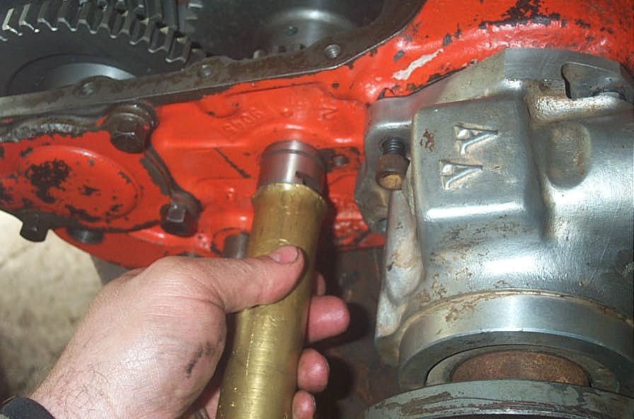
From the front of the case, and using a brass or other soft drift, drive the intermediate shaft to the rear of the case... | ||||||||||||||||||||||||||||||||||||||||||||||||||||||||||||||||||||||||||||||||||||||||||||||||||||||||||||||||||||||||||||||||||||||||||||||||||||||||
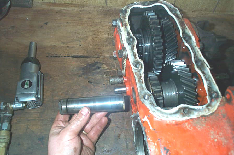 |
...and then remove it from the case. | ||||||||||||||||||||||||||||||||||||||||||||||||||||||||||||||||||||||||||||||||||||||||||||||||||||||||||||||||||||||||||||||||||||||||||||||||||||||||
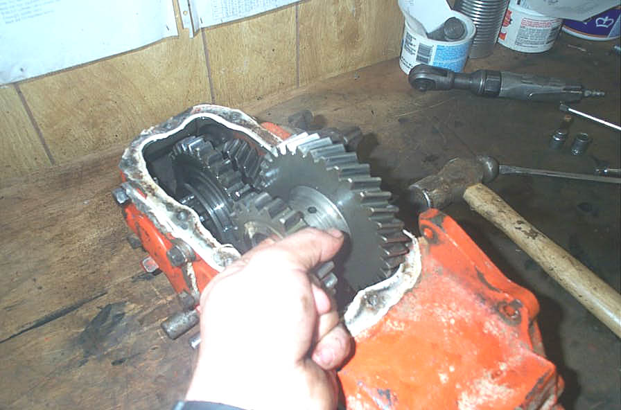 |
Wiggle the rear sliding gear out of the way (now that it is released from its shift fork) and then lift the intermediate gear from the case. | ||||||||||||||||||||||||||||||||||||||||||||||||||||||||||||||||||||||||||||||||||||||||||||||||||||||||||||||||||||||||||||||||||||||||||||||||||||||||
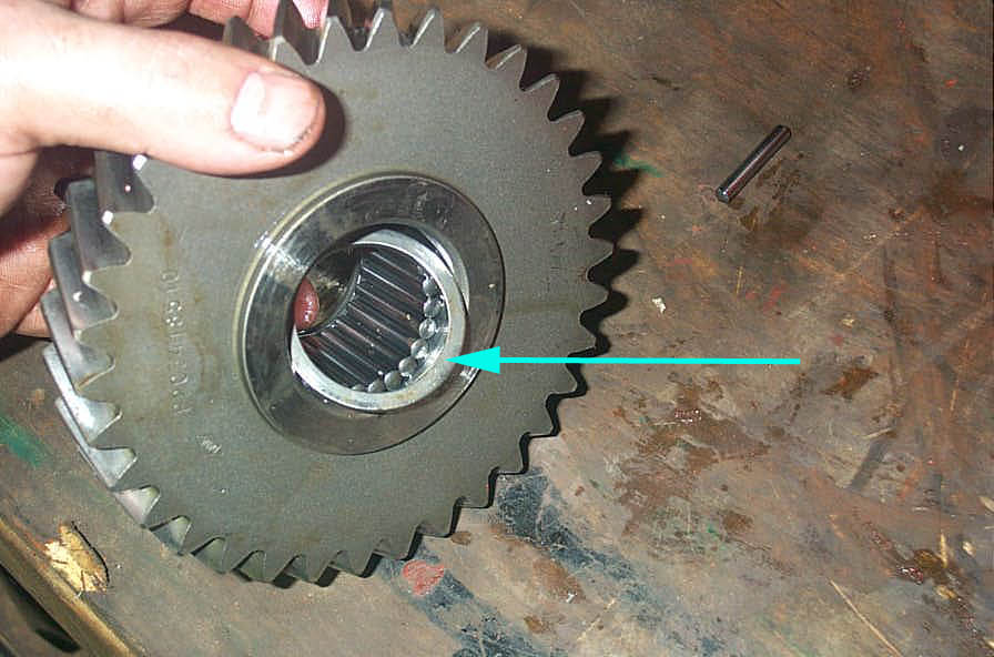 |
Be careful when removing the intermediate gear, as their are 3 silver bearing spacers (one on each side (blue arrow) and one in the middle seperating the 2 rows of needle bearings) in the gear that sandwich the large roller bearings. Remove the gear, and then remove the bearing spacers and roller bearings and store them carefully out of the way. | ||||||||||||||||||||||||||||||||||||||||||||||||||||||||||||||||||||||||||||||||||||||||||||||||||||||||||||||||||||||||||||||||||||||||||||||||||||||||
 |
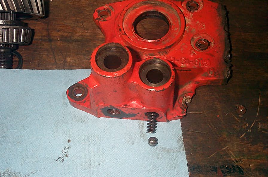
If you are not careful - and you drop or bobble the intermediate gear - this is what you get. | ||||||||||||||||||||||||||||||||||||||||||||||||||||||||||||||||||||||||||||||||||||||||||||||||||||||||||||||||||||||||||||||||||||||||||||||||||||||||
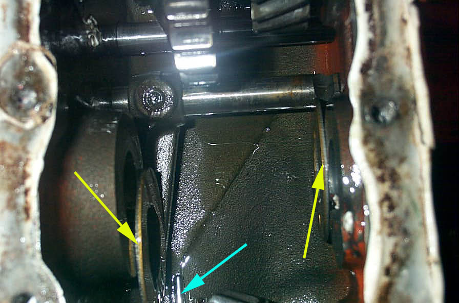 |
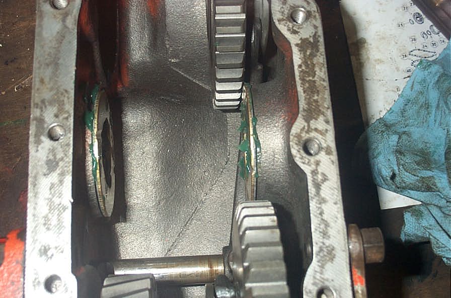
Once you have removed the intermediate gear, there will be 2 thrust washers left in the case (yellow arrows). Make a careful check for any loose needle bearings still in the case (blue arrow) | ||||||||||||||||||||||||||||||||||||||||||||||||||||||||||||||||||||||||||||||||||||||||||||||||||||||||||||||||||||||||||||||||||||||||||||||||||||||||
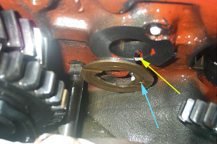 |
Take note of the orientation of the thrust washers for reassembly time. Each has a small tab (blue arrow) that indexes with a slot in the case (yellow arrow). | ||||||||||||||||||||||||||||||||||||||||||||||||||||||||||||||||||||||||||||||||||||||||||||||||||||||||||||||||||||||||||||||||||||||||||||||||||||||||
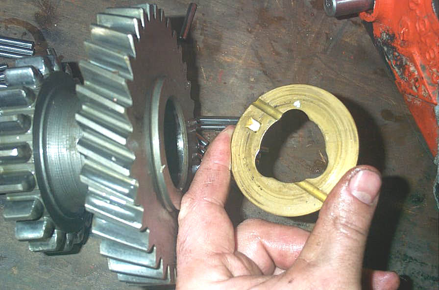 |
This shot shows the inside face (i.e. the side that faces towards the middle of the case) of the thrust washer. This is the side that goes up against the intermediate gear on installation. | ||||||||||||||||||||||||||||||||||||||||||||||||||||||||||||||||||||||||||||||||||||||||||||||||||||||||||||||||||||||||||||||||||||||||||||||||||||||||
 |
Once the intermediate gear is removed, you have room to reach in and wiggle out the rear sliding gear. | ||||||||||||||||||||||||||||||||||||||||||||||||||||||||||||||||||||||||||||||||||||||||||||||||||||||||||||||||||||||||||||||||||||||||||||||||||||||||
 |
Next remove the nut retaining the front output yoke. | ||||||||||||||||||||||||||||||||||||||||||||||||||||||||||||||||||||||||||||||||||||||||||||||||||||||||||||||||||||||||||||||||||||||||||||||||||||||||
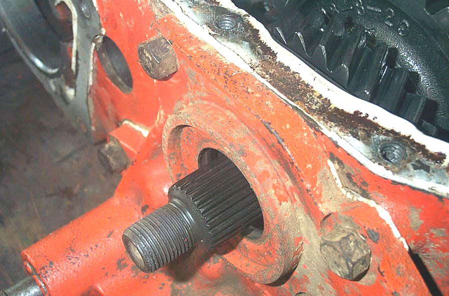 |
Remove the nut, washer, yoke and shim washer from the shaft and you are left with this. | ||||||||||||||||||||||||||||||||||||||||||||||||||||||||||||||||||||||||||||||||||||||||||||||||||||||||||||||||||||||||||||||||||||||||||||||||||||||||
 |
Next remove the bolts that hold the front output housing to the case. | ||||||||||||||||||||||||||||||||||||||||||||||||||||||||||||||||||||||||||||||||||||||||||||||||||||||||||||||||||||||||||||||||||||||||||||||||||||||||
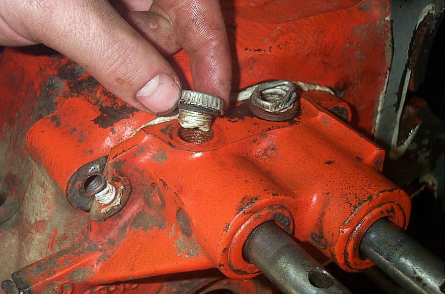 |
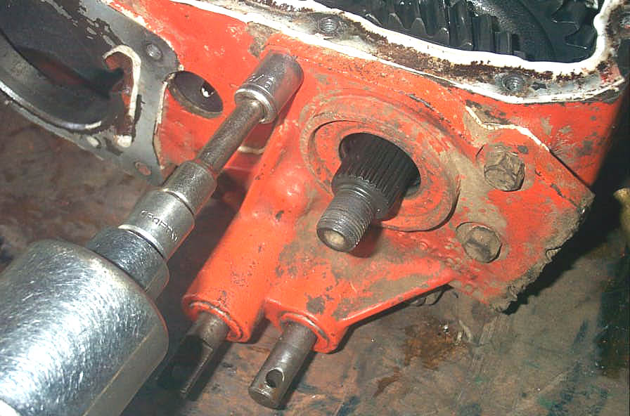
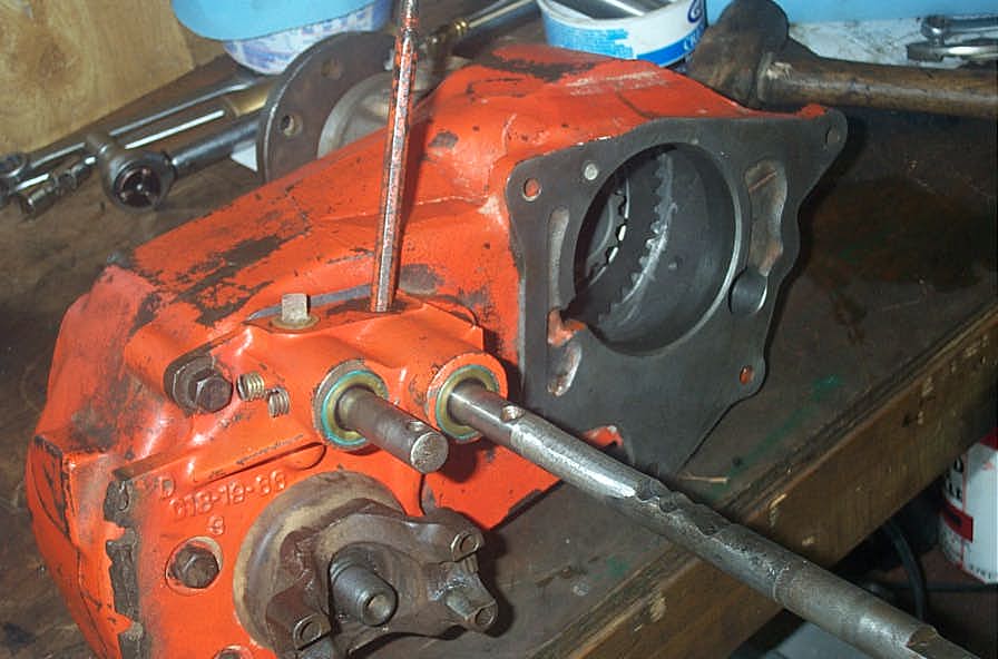
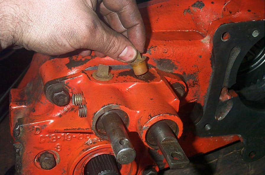
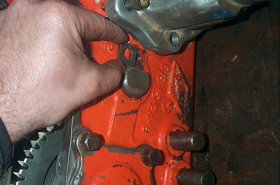
Tap or pull both shift rods to their centre (Neutral) positions. Next, remove the caps covering the detent balls and springs (also called "poppet balls" - these springs and round ball bearings are those that keep the shift lever(s) in the gear you select.) I found the easiest way to shift the rods was to insert a small punch through the hole in the end and use it for leverage. |
||||||||||||||||||||||||||||||||||||||||||||||||||||||||||||||||||||||||||||||||||||||||||||||||||||||||||||||||||||||||||||||||||||||||||||||||||||||||
 |
This shot shows the poppet ball and spring in relation to the housing. | ||||||||||||||||||||||||||||||||||||||||||||||||||||||||||||||||||||||||||||||||||||||||||||||||||||||||||||||||||||||||||||||||||||||||||||||||||||||||
 |
Remove the rear output shift fork set screw with an Allen wrench. | ||||||||||||||||||||||||||||||||||||||||||||||||||||||||||||||||||||||||||||||||||||||||||||||||||||||||||||||||||||||||||||||||||||||||||||||||||||||||
 |
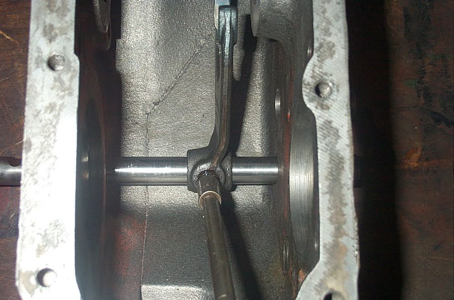
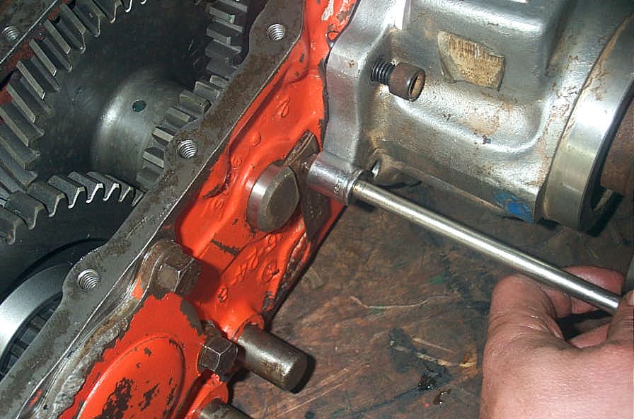
Rotate the rear shift rod 1/4 turn to free it from the shift interlock pill (this is the capsule shaped pill that rests between the 2 rods, preventing the stock case from being shifted into 2 different ratios front and rear.) Then, grasp the rear shift rod cap at the rear of the case with pliers, and twist / pull it free (it is just a press fit). Then take a brass or other soft punch and drive the rear shift rod out of the case from the rear. As you drive it out, catch the detent spring and ball as they come out of their housing. | ||||||||||||||||||||||||||||||||||||||||||||||||||||||||||||||||||||||||||||||||||||||||||||||||||||||||||||||||||||||||||||||||||||||||||||||||||||||||
 |
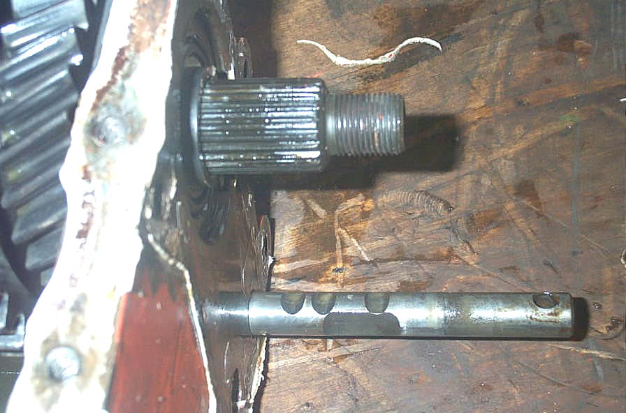
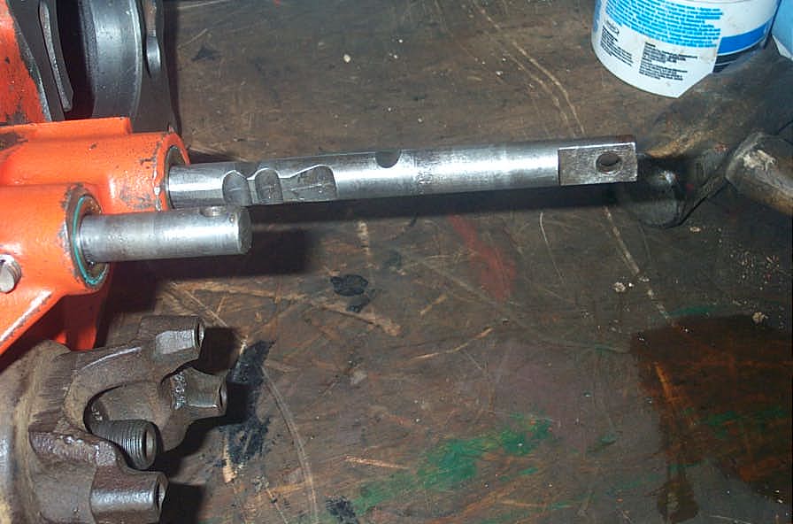
Removed shift rod and poppet ball. Note on the shift rod, from left to right, you see the shift fork set screw detent, followed by the three gear selection detents. The interlock detent is not visible in this shot. | ||||||||||||||||||||||||||||||||||||||||||||||||||||||||||||||||||||||||||||||||||||||||||||||||||||||||||||||||||||||||||||||||||||||||||||||||||||||||
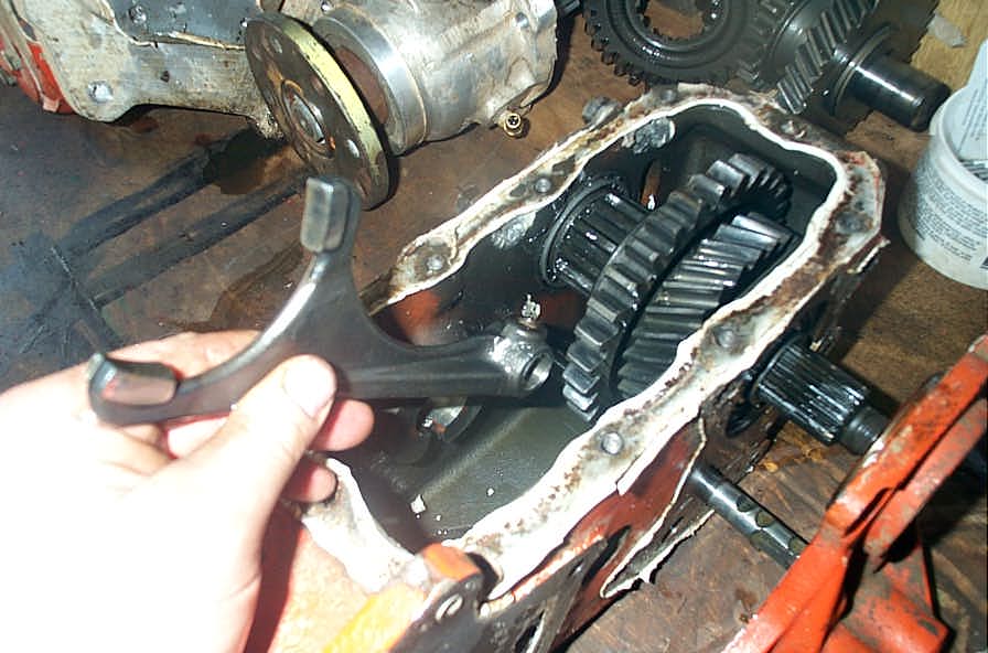 |
With the shift rod removed, remove the shift fork from the case, noting its orientation for installation. | ||||||||||||||||||||||||||||||||||||||||||||||||||||||||||||||||||||||||||||||||||||||||||||||||||||||||||||||||||||||||||||||||||||||||||||||||||||||||
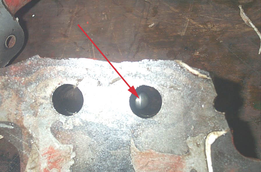 |
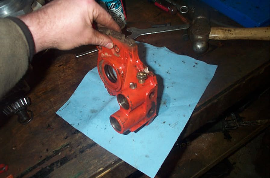
Next, remove the front output housing from the case, catching the front shift rod poppet ball and spring as you do so. If you look at the shift rod holes in the housing from the rear (the face that mates to the case) you can see the interlock pill where it sits in the housing between the shift rods (red arrow). You may have to tilt the housing side to side so it is visible through the shift rod holes. | ||||||||||||||||||||||||||||||||||||||||||||||||||||||||||||||||||||||||||||||||||||||||||||||||||||||||||||||||||||||||||||||||||||||||||||||||||||||||
 |
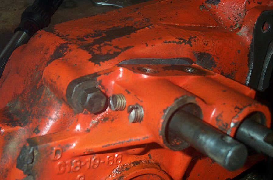
You are now left with just the front shift rod protruding. | ||||||||||||||||||||||||||||||||||||||||||||||||||||||||||||||||||||||||||||||||||||||||||||||||||||||||||||||||||||||||||||||||||||||||||||||||||||||||
 |
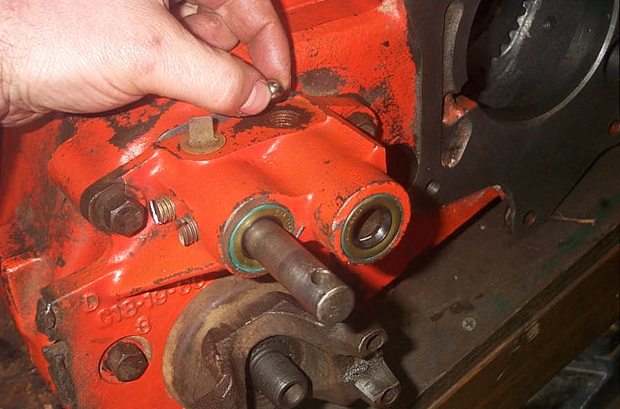
Remove the front output shaft bearing cap from the rear of the case. | ||||||||||||||||||||||||||||||||||||||||||||||||||||||||||||||||||||||||||||||||||||||||||||||||||||||||||||||||||||||||||||||||||||||||||||||||||||||||
 |
Be careful not to lose or damage the delicate shims between the bearing cap and the case (blue arrow). | ||||||||||||||||||||||||||||||||||||||||||||||||||||||||||||||||||||||||||||||||||||||||||||||||||||||||||||||||||||||||||||||||||||||||||||||||||||||||
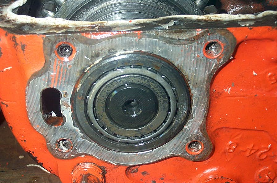 |
Rear of front output shaft, under bearing cap. | ||||||||||||||||||||||||||||||||||||||||||||||||||||||||||||||||||||||||||||||||||||||||||||||||||||||||||||||||||||||||||||||||||||||||||||||||||||||||
 |
You should now be at this stage here. | ||||||||||||||||||||||||||||||||||||||||||||||||||||||||||||||||||||||||||||||||||||||||||||||||||||||||||||||||||||||||||||||||||||||||||||||||||||||||
 |
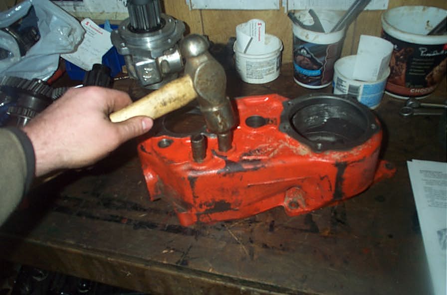
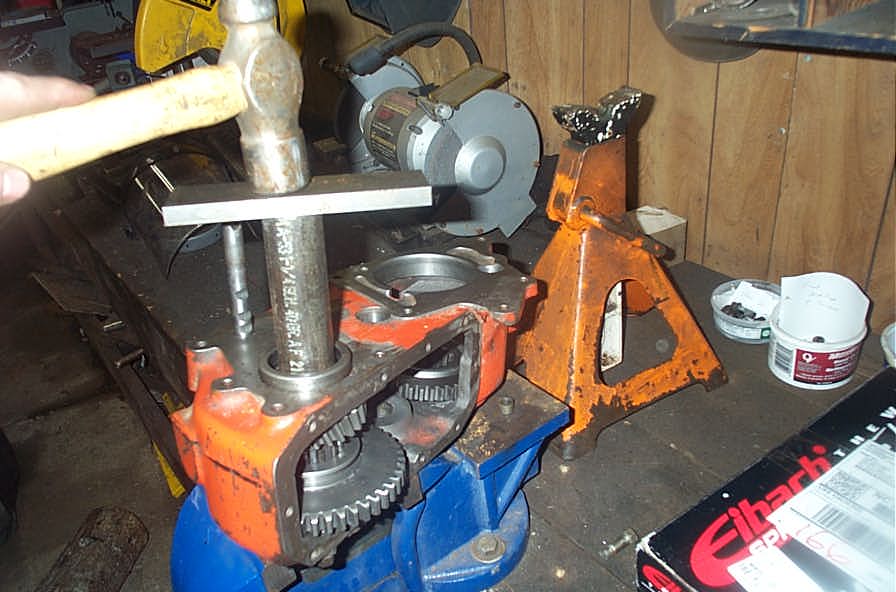
Using a hammer and brass or wooden drift, strike the front of the front output shaft and drive the front output shaft towards the rear of the case, then remove the bearing cup (race) from the cone (bearing). | ||||||||||||||||||||||||||||||||||||||||||||||||||||||||||||||||||||||||||||||||||||||||||||||||||||||||||||||||||||||||||||||||||||||||||||||||||||||||
 |
You should now have a transfer case that looks like this | ||||||||||||||||||||||||||||||||||||||||||||||||||||||||||||||||||||||||||||||||||||||||||||||||||||||||||||||||||||||||||||||||||||||||||||||||||||||||
 |
Remove the front output shaft rear bearing from the shaft using a bearing separator and harmonic-balancer type puller. | ||||||||||||||||||||||||||||||||||||||||||||||||||||||||||||||||||||||||||||||||||||||||||||||||||||||||||||||||||||||||||||||||||||||||||||||||||||||||
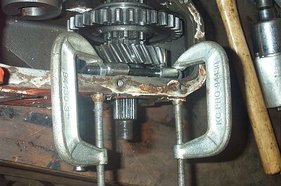 |
Now comes the only slightly tricky part of the whole disassembly. You have to remove the front bearing from the front output shaft. I used a small bearing separator to get behind the bearing, inside the case. I then used 2 small c-clamps to hold the bearing separator against the front of the case... | ||||||||||||||||||||||||||||||||||||||||||||||||||||||||||||||||||||||||||||||||||||||||||||||||||||||||||||||||||||||||||||||||||||||||||||||||||||||||
 |
... and then used a brass drift to drive the output shaft back through the case , separating the bearing from the shaft. | ||||||||||||||||||||||||||||||||||||||||||||||||||||||||||||||||||||||||||||||||||||||||||||||||||||||||||||||||||||||||||||||||||||||||||||||||||||||||
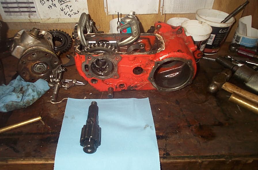 |
The shaft can then be removed through the rear of the case. | ||||||||||||||||||||||||||||||||||||||||||||||||||||||||||||||||||||||||||||||||||||||||||||||||||||||||||||||||||||||||||||||||||||||||||||||||||||||||
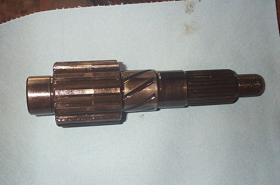 |
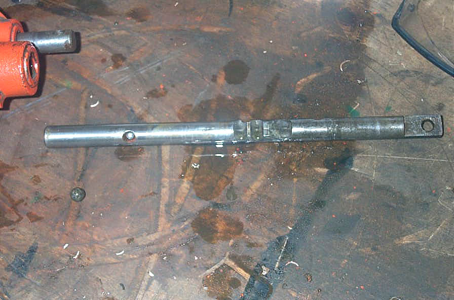
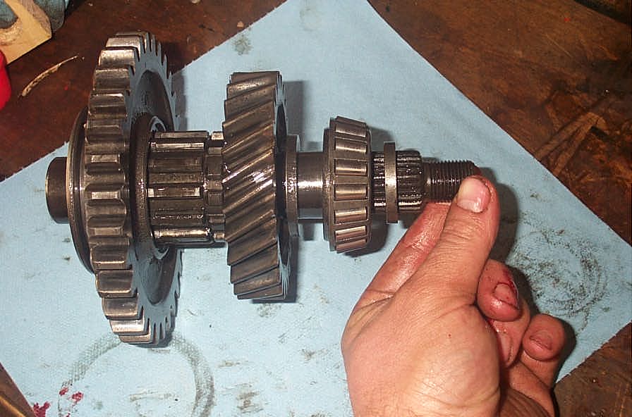
Detail of the removed front output shaft. | ||||||||||||||||||||||||||||||||||||||||||||||||||||||||||||||||||||||||||||||||||||||||||||||||||||||||||||||||||||||||||||||||||||||||||||||||||||||||
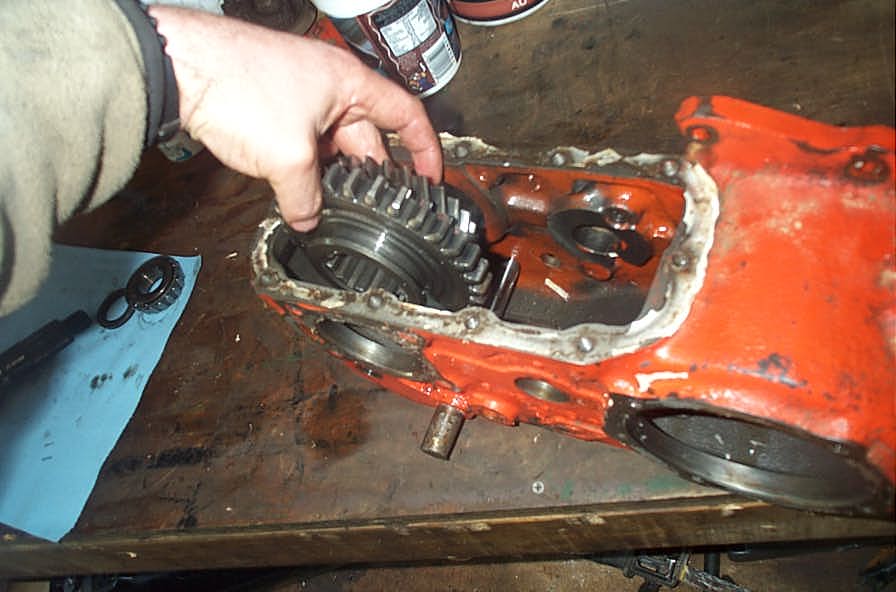 |
Once the shaft is removed, you can remove the front output gear and front sliding gear from the case. | ||||||||||||||||||||||||||||||||||||||||||||||||||||||||||||||||||||||||||||||||||||||||||||||||||||||||||||||||||||||||||||||||||||||||||||||||||||||||
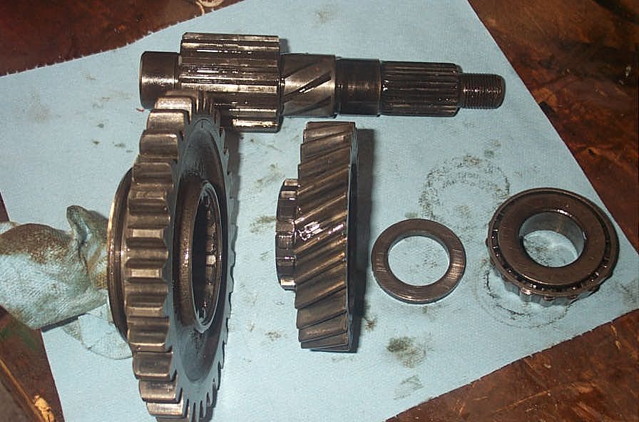 |
Shaft in the background, foreground showing from left to right (rear of case to front)
|
||||||||||||||||||||||||||||||||||||||||||||||||||||||||||||||||||||||||||||||||||||||||||||||||||||||||||||||||||||||||||||||||||||||||||||||||||||||||
 |
Components of front output shaft assembly in the order in which they are on the shaft when assembled. | ||||||||||||||||||||||||||||||||||||||||||||||||||||||||||||||||||||||||||||||||||||||||||||||||||||||||||||||||||||||||||||||||||||||||||||||||||||||||
 |
Case now looks like this. | ||||||||||||||||||||||||||||||||||||||||||||||||||||||||||||||||||||||||||||||||||||||||||||||||||||||||||||||||||||||||||||||||||||||||||||||||||||||||
 |
Remove front shift rod set screw. | ||||||||||||||||||||||||||||||||||||||||||||||||||||||||||||||||||||||||||||||||||||||||||||||||||||||||||||||||||||||||||||||||||||||||||||||||||||||||
 |
Pull shift rod from case, and disengage the front shift fork from the shift rod. | ||||||||||||||||||||||||||||||||||||||||||||||||||||||||||||||||||||||||||||||||||||||||||||||||||||||||||||||||||||||||||||||||||||||||||||||||||||||||
 |
Detail of shift rod removed from case, with shift fork reinstalled. To the left of the shift fork is the detent into which the set screw must index on assembly. | ||||||||||||||||||||||||||||||||||||||||||||||||||||||||||||||||||||||||||||||||||||||||||||||||||||||||||||||||||||||||||||||||||||||||||||||||||||||||
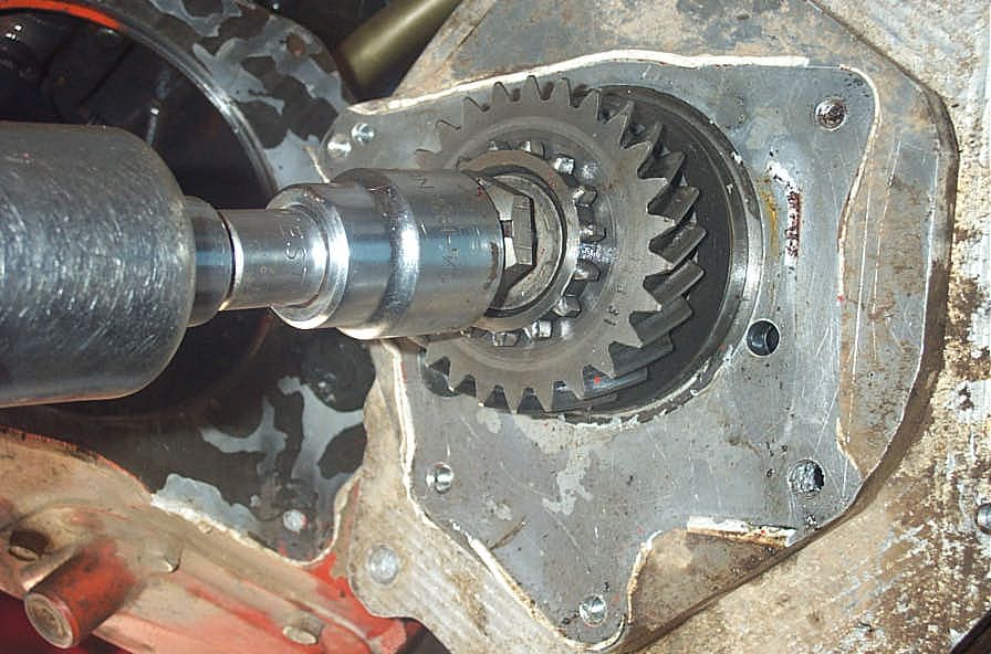 |
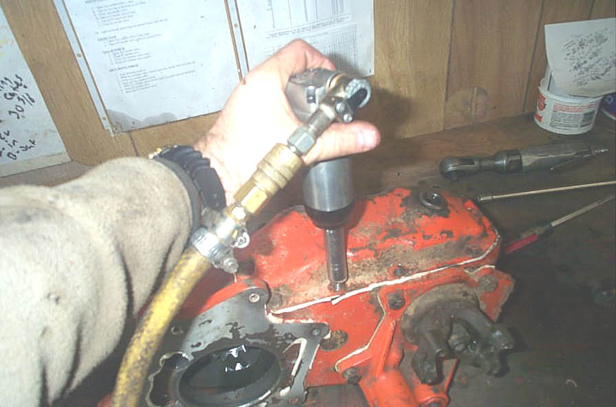
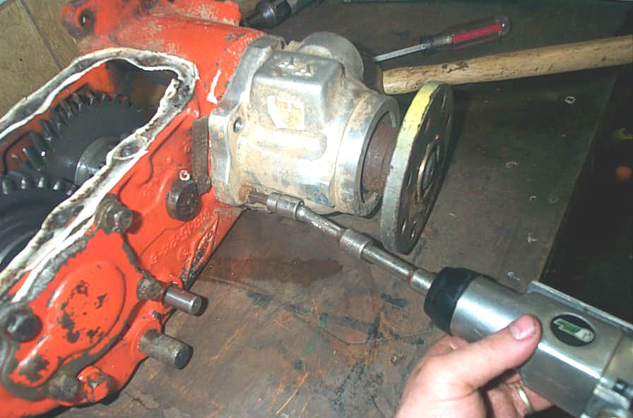
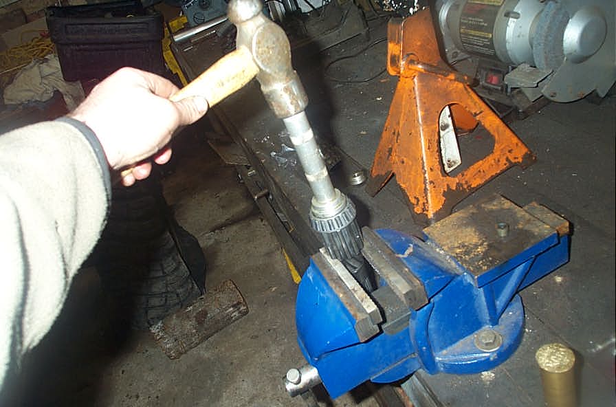
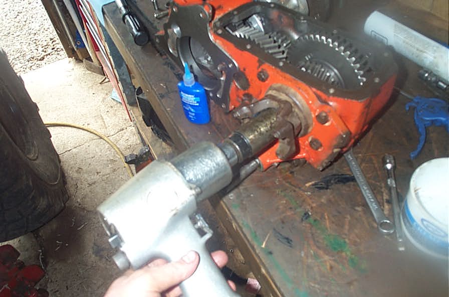
The final step of tear-down is to remove the main drive gear (input gear) from whatever it is attached to - in my case my doubler adapter. I used an impact wrench to break the nut loose... | ||||||||||||||||||||||||||||||||||||||||||||||||||||||||||||||||||||||||||||||||||||||||||||||||||||||||||||||||||||||||||||||||||||||||||||||||||||||||
 |
... and then a gear / bearing puller to separate the gear from the shaft. | ||||||||||||||||||||||||||||||||||||||||||||||||||||||||||||||||||||||||||||||||||||||||||||||||||||||||||||||||||||||||||||||||||||||||||||||||||||||||
 |
Once it is loose, remove the main drive gear from the shaft. | ||||||||||||||||||||||||||||||||||||||||||||||||||||||||||||||||||||||||||||||||||||||||||||||||||||||||||||||||||||||||||||||||||||||||||||||||||||||||
Once everything is torn down, carefully clean and inspect all parts, ready for installation of the Tera Low kit. You want to thoroughly degrease the case so that any grinding dust created when you clearance the case for the new rear sliding gear does not get trapped and form a grinding paste. Tera Low Low-20 Kit |
|||||||||||||||||||||||||||||||||||||||||||||||||||||||||||||||||||||||||||||||||||||||||||||||||||||||||||||||||||||||||||||||||||||||||||||||||||||||||
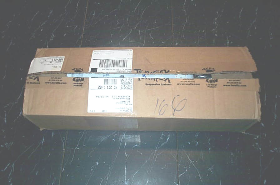 |
The kit arrives well packaged in a single box. | ||||||||||||||||||||||||||||||||||||||||||||||||||||||||||||||||||||||||||||||||||||||||||||||||||||||||||||||||||||||||||||||||||||||||||||||||||||||||
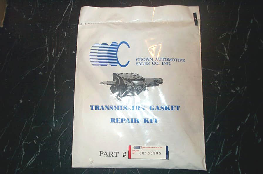 |
It includes a third-party gasket and seal kit from Crown Automotive - pat number J8130995 for the Jeep D20 application. The seals are useful, but the gaskets are junk - none of them fit properly and you may as well throw them away right now. No big deal - you want to use silicone anyway. | ||||||||||||||||||||||||||||||||||||||||||||||||||||||||||||||||||||||||||||||||||||||||||||||||||||||||||||||||||||||||||||||||||||||||||||||||||||||||
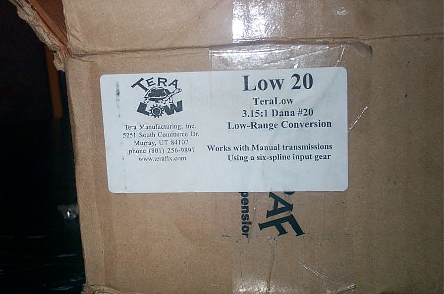 |
Box label and part number. | ||||||||||||||||||||||||||||||||||||||||||||||||||||||||||||||||||||||||||||||||||||||||||||||||||||||||||||||||||||||||||||||||||||||||||||||||||||||||
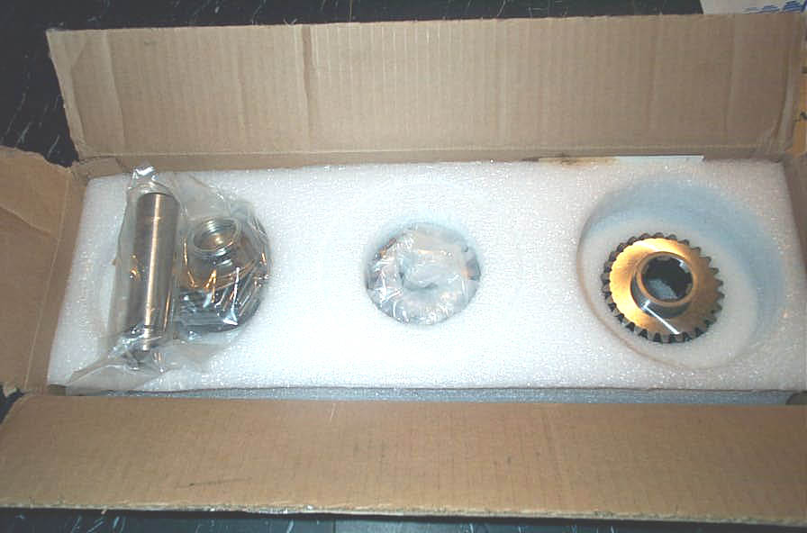 |
The gears are well protected by form-fitting packing foam. | ||||||||||||||||||||||||||||||||||||||||||||||||||||||||||||||||||||||||||||||||||||||||||||||||||||||||||||||||||||||||||||||||||||||||||||||||||||||||
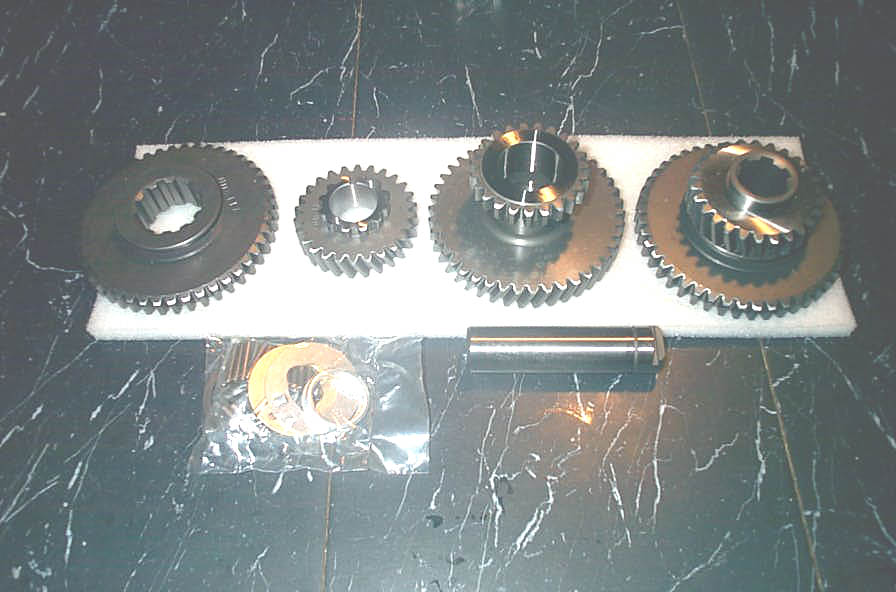 |
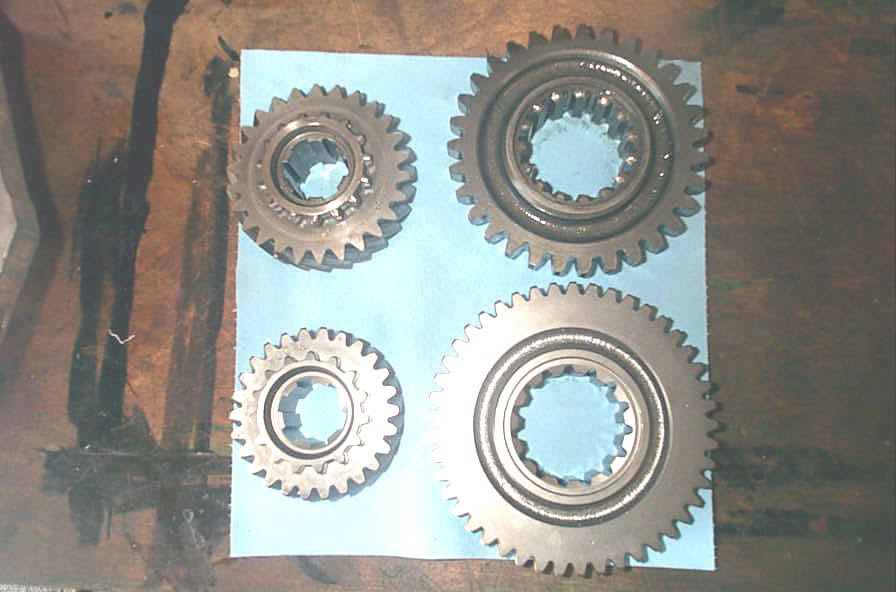
The gear set all laid out. From left to right:
In the foreground are the new intermediate gear thrust washers, needle bearings, and the new intermediate gear shaft. |
||||||||||||||||||||||||||||||||||||||||||||||||||||||||||||||||||||||||||||||||||||||||||||||||||||||||||||||||||||||||||||||||||||||||||||||||||||||||
|
Detail of Tera Low intermediate gear and front gears. | ||||||||||||||||||||||||||||||||||||||||||||||||||||||||||||||||||||||||||||||||||||||||||||||||||||||||||||||||||||||||||||||||||||||||||||||||||||||||
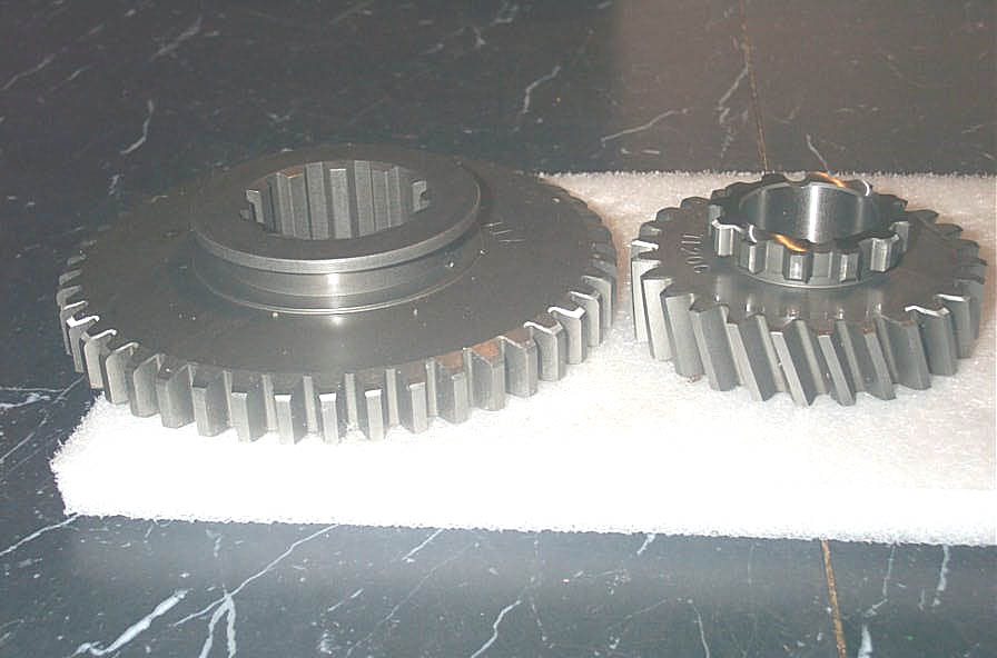 |
Detail of rear sliding gear and main drive gear. | ||||||||||||||||||||||||||||||||||||||||||||||||||||||||||||||||||||||||||||||||||||||||||||||||||||||||||||||||||||||||||||||||||||||||||||||||||||||||
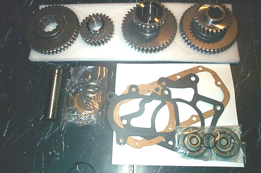 |
The complete kit. | ||||||||||||||||||||||||||||||||||||||||||||||||||||||||||||||||||||||||||||||||||||||||||||||||||||||||||||||||||||||||||||||||||||||||||||||||||||||||
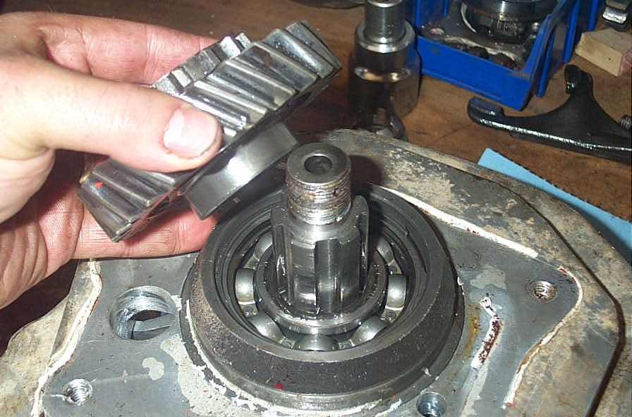
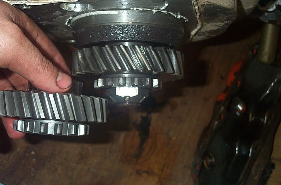 |
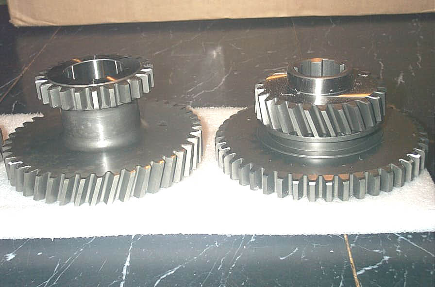
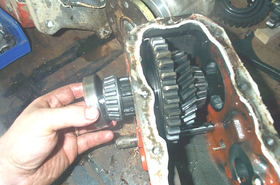
Comparison of the old drive gear installed, and the new Tera Low drive gear in hand. | ||||||||||||||||||||||||||||||||||||||||||||||||||||||||||||||||||||||||||||||||||||||||||||||||||||||||||||||||||||||||||||||||||||||||||||||||||||||||
Clearance checking and case grinding |
|||||||||||||||||||||||||||||||||||||||||||||||||||||||||||||||||||||||||||||||||||||||||||||||||||||||||||||||||||||||||||||||||||||||||||||||||||||||||
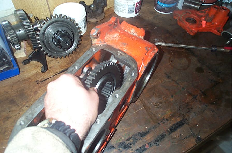 |
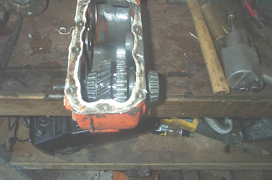
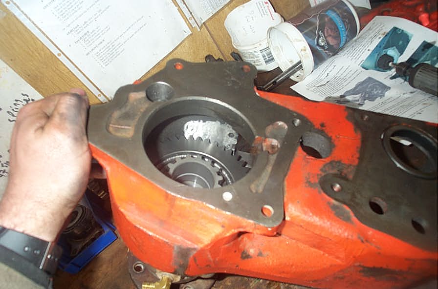
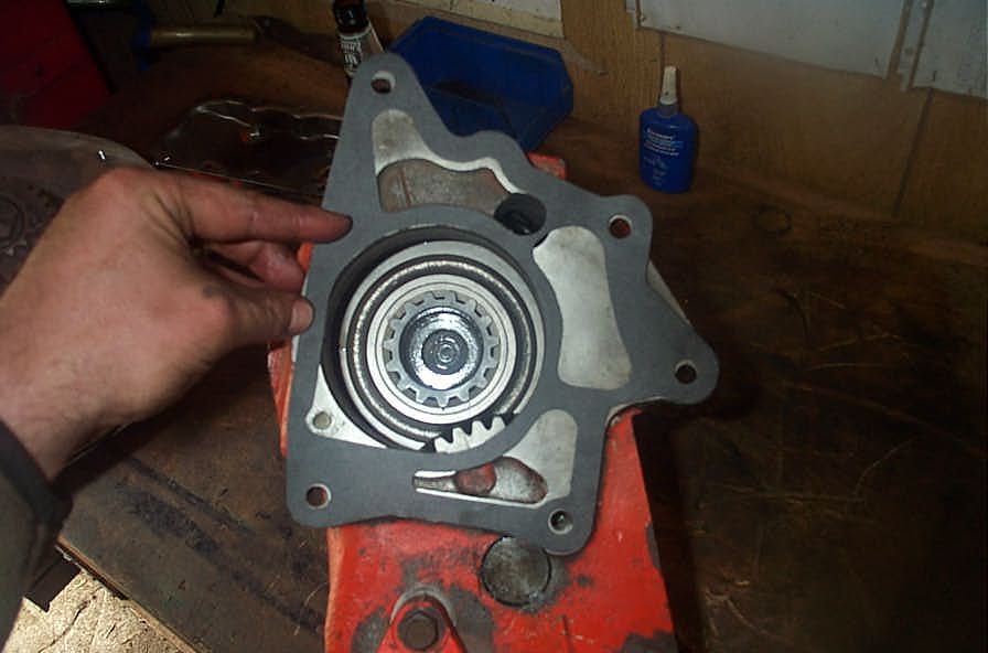
Most Dana 20 cases will require some minor clearance grinding to fit the new, larger rear sliding gear. Place the rear sliding gear in the case and then put the output housing in place so you can place the sliding gear on the rear output shaft. | ||||||||||||||||||||||||||||||||||||||||||||||||||||||||||||||||||||||||||||||||||||||||||||||||||||||||||||||||||||||||||||||||||||||||||||||||||||||||
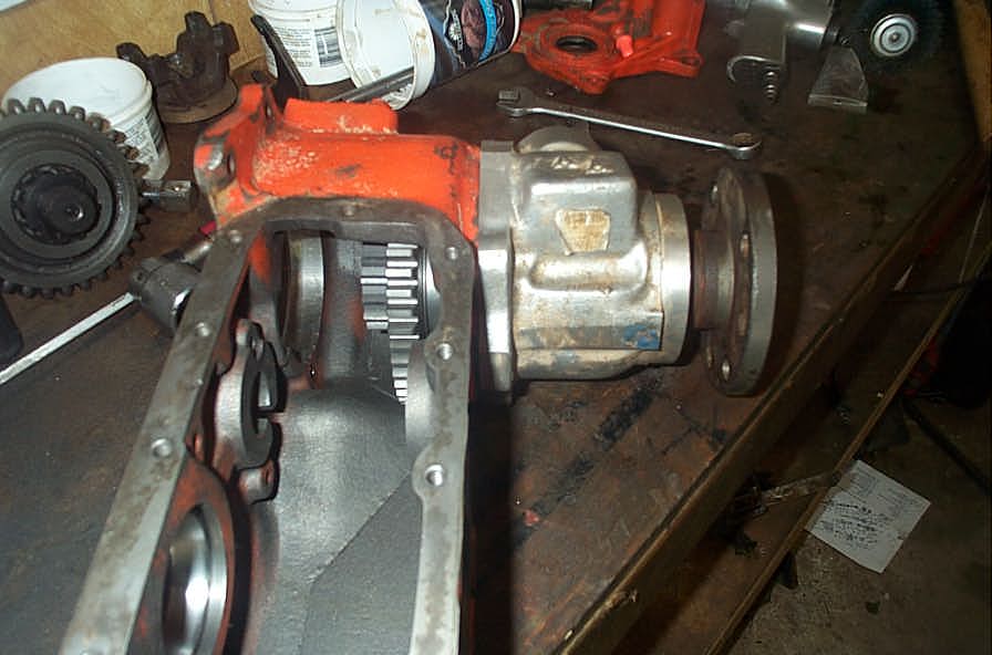 |
You will have to check for clearance and mark the case for any required grinding through the entire range of travel of the rear sliding gear - from all the way to the rear of the case, as shown in this pic... | ||||||||||||||||||||||||||||||||||||||||||||||||||||||||||||||||||||||||||||||||||||||||||||||||||||||||||||||||||||||||||||||||||||||||||||||||||||||||
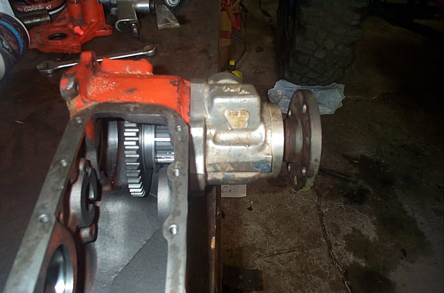 |
... to all the way towards the front of the case, on the shaft, as shown in this pic. If you don't do this, you could find yourself clearancing the case, assembling everything, and THEN finding out that the sliding gear will not slide properly. Ask me how I know! | ||||||||||||||||||||||||||||||||||||||||||||||||||||||||||||||||||||||||||||||||||||||||||||||||||||||||||||||||||||||||||||||||||||||||||||||||||||||||
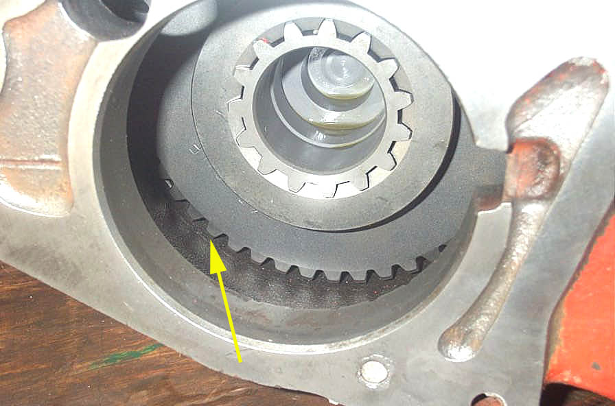 |
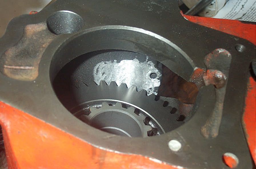
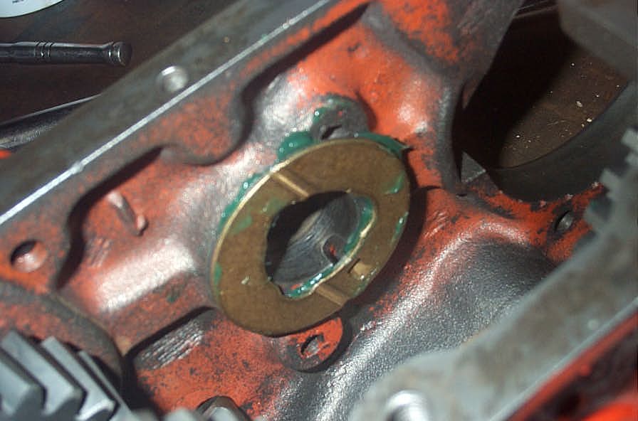
Rotate the rear output shaft and check where clearancing is required between the gear and case. Yellow arrow shows the general area. | ||||||||||||||||||||||||||||||||||||||||||||||||||||||||||||||||||||||||||||||||||||||||||||||||||||||||||||||||||||||||||||||||||||||||||||||||||||||||
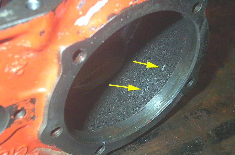 |
After rotating the gear in the case, the slight contact between the gear teeth and the case left noticeable marks in the casting flash of the case (yellow arrows), making it easy to know where to grind. | ||||||||||||||||||||||||||||||||||||||||||||||||||||||||||||||||||||||||||||||||||||||||||||||||||||||||||||||||||||||||||||||||||||||||||||||||||||||||
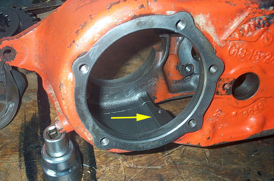 |
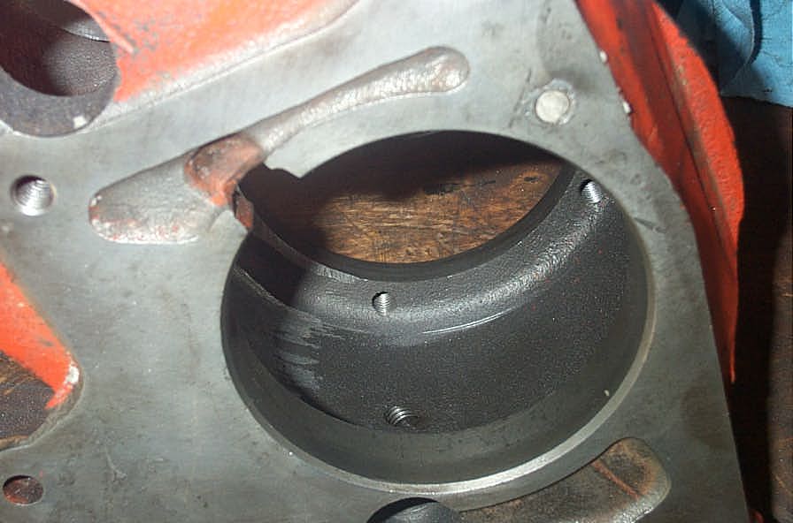
This view, from the rear of the case with rear output housing removed, shows the ridge that needs to be smoothed out (yellow arrow). | ||||||||||||||||||||||||||||||||||||||||||||||||||||||||||||||||||||||||||||||||||||||||||||||||||||||||||||||||||||||||||||||||||||||||||||||||||||||||
 |
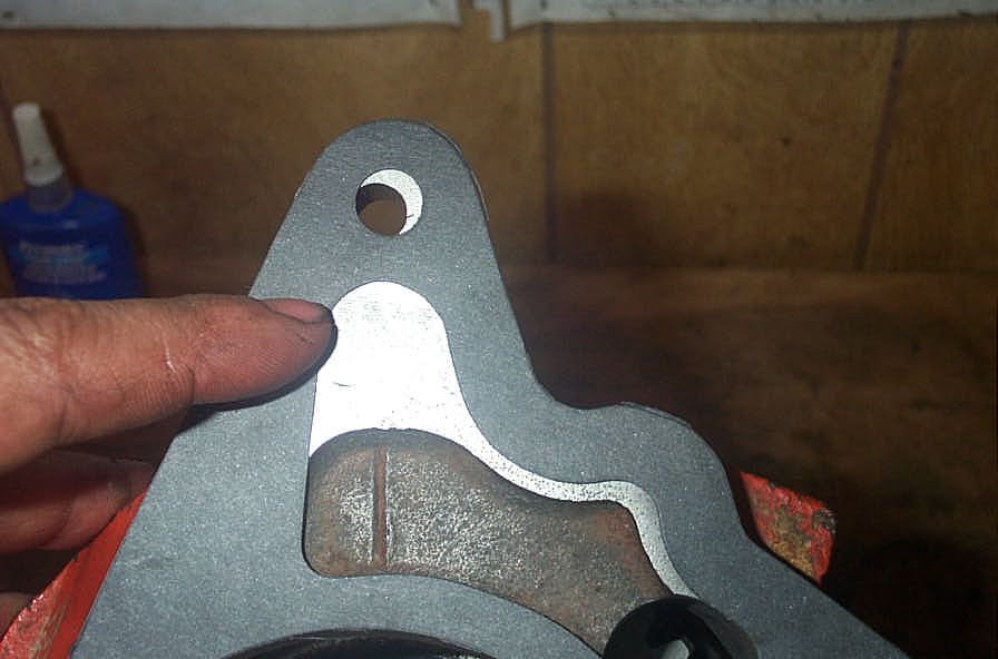
Shot of the lip smoothed down with a die grinder. | ||||||||||||||||||||||||||||||||||||||||||||||||||||||||||||||||||||||||||||||||||||||||||||||||||||||||||||||||||||||||||||||||||||||||||||||||||||||||
 |
Close up shot of same. | ||||||||||||||||||||||||||||||||||||||||||||||||||||||||||||||||||||||||||||||||||||||||||||||||||||||||||||||||||||||||||||||||||||||||||||||||||||||||
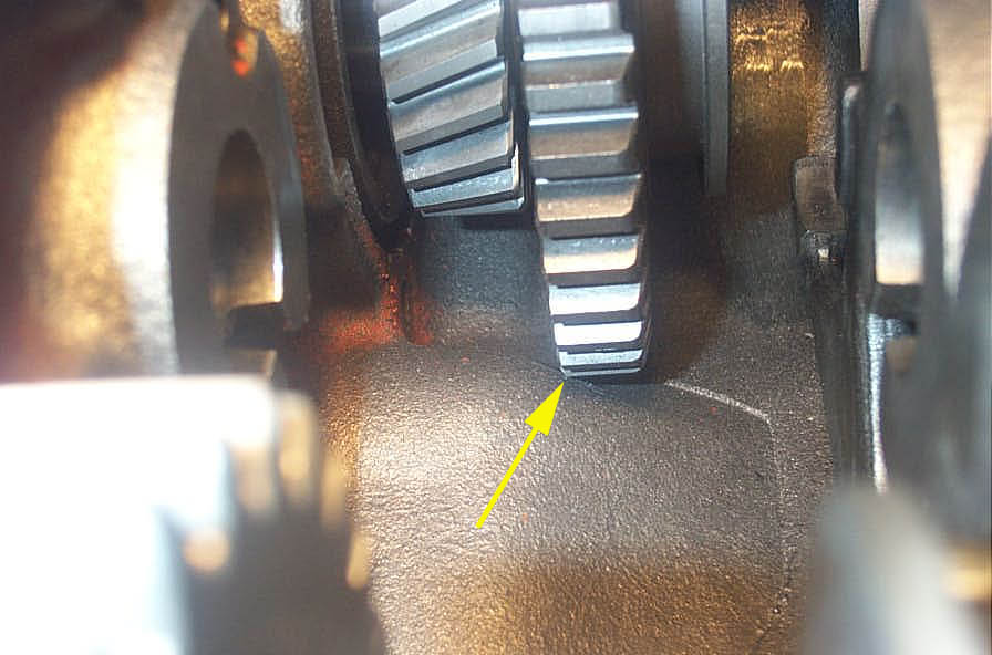 |
With the rear sliding gear all the way to the front on the rear output shaft, slight grinding of the hump may be required. Here you can see the gear teeth just contacting. | ||||||||||||||||||||||||||||||||||||||||||||||||||||||||||||||||||||||||||||||||||||||||||||||||||||||||||||||||||||||||||||||||||||||||||||||||||||||||
 |
Clearance grinding complete | ||||||||||||||||||||||||||||||||||||||||||||||||||||||||||||||||||||||||||||||||||||||||||||||||||||||||||||||||||||||||||||||||||||||||||||||||||||||||
 |
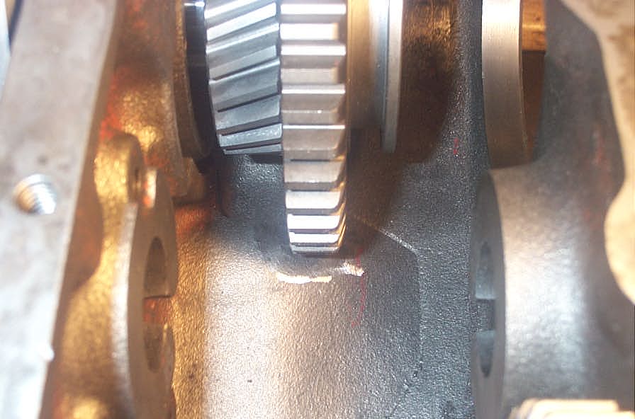
Here you can see the final spot that needed a little clearancing... | ||||||||||||||||||||||||||||||||||||||||||||||||||||||||||||||||||||||||||||||||||||||||||||||||||||||||||||||||||||||||||||||||||||||||||||||||||||||||
 |
... and the finished grinding. The grinding involved was quite minimal, and only took a few minutes with a small air-powered die grinder and a couple of different shaped grinding stones. I used a cone shaped one and a cylinder shaped one. When you're done, it is ESSENTIAL that you thoroughly clean the entire case and any parts in solvent and dry them. You do not want any grinding dust to find it's way into the bearings or between the gears. |
||||||||||||||||||||||||||||||||||||||||||||||||||||||||||||||||||||||||||||||||||||||||||||||||||||||||||||||||||||||||||||||||||||||||||||||||||||||||
Installing the kitOnce you have the old case torn down, clearanced, cleaned and inspected, it's time to install the new gear set. Installing Main Drive Gear |
|||||||||||||||||||||||||||||||||||||||||||||||||||||||||||||||||||||||||||||||||||||||||||||||||||||||||||||||||||||||||||||||||||||||||||||||||||||||||
 |
The first step is to install the new main drive gear. Place it on the transmission or doubler output shaft. | ||||||||||||||||||||||||||||||||||||||||||||||||||||||||||||||||||||||||||||||||||||||||||||||||||||||||||||||||||||||||||||||||||||||||||||||||||||||||
|
Install the washer and nut using thread locking compound, torque to spec, and if your installation requires it, install a new cotter pin. | ||||||||||||||||||||||||||||||||||||||||||||||||||||||||||||||||||||||||||||||||||||||||||||||||||||||||||||||||||||||||||||||||||||||||||||||||||||||||
 |
My doubler all cleaned up and ready for reassembly. | ||||||||||||||||||||||||||||||||||||||||||||||||||||||||||||||||||||||||||||||||||||||||||||||||||||||||||||||||||||||||||||||||||||||||||||||||||||||||
 |
Another look at the new gears that go in the case. | ||||||||||||||||||||||||||||||||||||||||||||||||||||||||||||||||||||||||||||||||||||||||||||||||||||||||||||||||||||||||||||||||||||||||||||||||||||||||
Reassembling the Case |
|||||||||||||||||||||||||||||||||||||||||||||||||||||||||||||||||||||||||||||||||||||||||||||||||||||||||||||||||||||||||||||||||||||||||||||||||||||||||
 |
Place a little RTV sealant on the ends of the shift rod caps and tap them into their bores in the case. | ||||||||||||||||||||||||||||||||||||||||||||||||||||||||||||||||||||||||||||||||||||||||||||||||||||||||||||||||||||||||||||||||||||||||||||||||||||||||
 |
Slide the front shift rod part way into the case and slip the front shift fork over the end and onto the rod. | ||||||||||||||||||||||||||||||||||||||||||||||||||||||||||||||||||||||||||||||||||||||||||||||||||||||||||||||||||||||||||||||||||||||||||||||||||||||||
 |
Line up the shift fork with the detent in the shift rod and install the set screw. Tighten to 14 ft lbs. | ||||||||||||||||||||||||||||||||||||||||||||||||||||||||||||||||||||||||||||||||||||||||||||||||||||||||||||||||||||||||||||||||||||||||||||||||||||||||
 |
Place the rear sliding gear and rear shift fork into the case in their proper orientation. Make sure the sliding gear is installed the right way around - with the slot in the sliding gear towards the rear of the case. | ||||||||||||||||||||||||||||||||||||||||||||||||||||||||||||||||||||||||||||||||||||||||||||||||||||||||||||||||||||||||||||||||||||||||||||||||||||||||
 |
Using a bearing driver or press, drive the front output shaft rear roller bearing in place on the shaft. | ||||||||||||||||||||||||||||||||||||||||||||||||||||||||||||||||||||||||||||||||||||||||||||||||||||||||||||||||||||||||||||||||||||||||||||||||||||||||
 |
Place the front sliding gear and front output gear in place in the case. Make sure the slot in the front sliding gear faces the rear of the case and engages with the front shift fork. Hold both gears in place in the case... | ||||||||||||||||||||||||||||||||||||||||||||||||||||||||||||||||||||||||||||||||||||||||||||||||||||||||||||||||||||||||||||||||||||||||||||||||||||||||
 |
... and then slide the front output shaft into the case from the rear of the case. | ||||||||||||||||||||||||||||||||||||||||||||||||||||||||||||||||||||||||||||||||||||||||||||||||||||||||||||||||||||||||||||||||||||||||||||||||||||||||
 |
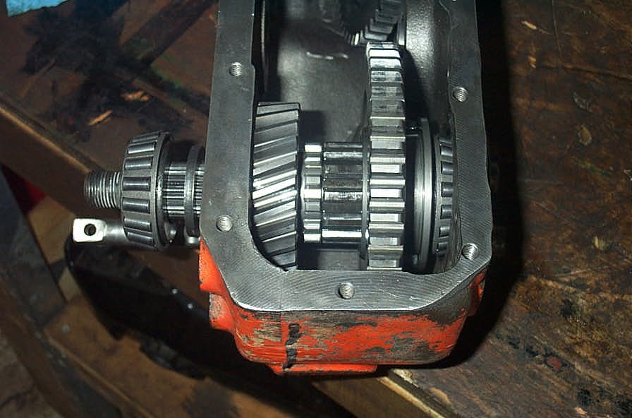
The front output shaft and gears in place should look like this. | ||||||||||||||||||||||||||||||||||||||||||||||||||||||||||||||||||||||||||||||||||||||||||||||||||||||||||||||||||||||||||||||||||||||||||||||||||||||||
 |
Using an appropriate driver, drive the front output shaft rear bearing cup (race) into its bore in the rear of the case. | ||||||||||||||||||||||||||||||||||||||||||||||||||||||||||||||||||||||||||||||||||||||||||||||||||||||||||||||||||||||||||||||||||||||||||||||||||||||||
 |
Place a thin bead of RTV sealant on the shim closest to the case, then install the shims and bearing cap and tighten the bolts to 30 ft lbs. | ||||||||||||||||||||||||||||||||||||||||||||||||||||||||||||||||||||||||||||||||||||||||||||||||||||||||||||||||||||||||||||||||||||||||||||||||||||||||
 |
Slide the front output shaft washer and front roller bearing onto the shaft. | ||||||||||||||||||||||||||||||||||||||||||||||||||||||||||||||||||||||||||||||||||||||||||||||||||||||||||||||||||||||||||||||||||||||||||||||||||||||||
 |
Drive the roller bearing into place on the shaft - I used a length of 1.5" Schedule 40 pipe and a steel block. | ||||||||||||||||||||||||||||||||||||||||||||||||||||||||||||||||||||||||||||||||||||||||||||||||||||||||||||||||||||||||||||||||||||||||||||||||||||||||
 |
Next drive the front output shaft front bearing cup (race) into place - I used a length of 3" exhaust tube and steel block. | ||||||||||||||||||||||||||||||||||||||||||||||||||||||||||||||||||||||||||||||||||||||||||||||||||||||||||||||||||||||||||||||||||||||||||||||||||||||||
 |
Install a new front output shaft yoke seal and new shift rod seals in the front output housing. | ||||||||||||||||||||||||||||||||||||||||||||||||||||||||||||||||||||||||||||||||||||||||||||||||||||||||||||||||||||||||||||||||||||||||||||||||||||||||
 |
Lay a thin (1/8") bead of RTV sealant around the edges of the case where the front output housing mounts. Place the front shift rod detent spring in the front output housing, then start the housing onto the front shift rod (ignore the fact that the rear shift rod is installed in this pic). Place front poppet ball on top of spring and depress into housing with a punch, tilt transfer case to slide interlock pill to right if required, and slide the front output housing into place over the front shift rod. | ||||||||||||||||||||||||||||||||||||||||||||||||||||||||||||||||||||||||||||||||||||||||||||||||||||||||||||||||||||||||||||||||||||||||||||||||||||||||
 |
Place rear shift rod detent spring and poppet ball into front output housing. | ||||||||||||||||||||||||||||||||||||||||||||||||||||||||||||||||||||||||||||||||||||||||||||||||||||||||||||||||||||||||||||||||||||||||||||||||||||||||
 |
Depress poppet ball with punch, and slide rear shift rod into housing with the shift fork detent facing up. | ||||||||||||||||||||||||||||||||||||||||||||||||||||||||||||||||||||||||||||||||||||||||||||||||||||||||||||||||||||||||||||||||||||||||||||||||||||||||
 |
Once started past the poppet ball, rotate the rear shift rod 1/4 turn counterclockwise, as shown, so that poppet ball doesn't hang up on the detents in the shift rod. | ||||||||||||||||||||||||||||||||||||||||||||||||||||||||||||||||||||||||||||||||||||||||||||||||||||||||||||||||||||||||||||||||||||||||||||||||||||||||
|
Make sure the rear sliding gear and shift fork are positioned properly in case, and slide rear shift rod into case, and through shift fork. Align shift fork with shift fork detent in rear shift rod, then tighten set screw to 14 ft lbs. |
||||||||||||||||||||||||||||||||||||||||||||||||||||||||||||||||||||||||||||||||||||||||||||||||||||||||||||||||||||||||||||||||||||||||||||||||||||||||
 |
Install front output housing bolts and torque to 30 ft lbs. Install poppet ball caps. Check front output shaft end-play by prying the shaft alternately to the rear and then to the front of the case. The proper method is to measure the end-play with a dial indicator. I must admit - I went by "feel". End-play should be between .001 and .003 inch. If it needs to be adjusted, you do so by adding or subtracting the shims under the front output shaft rear bearing cap. Note that there are no extra shims in the kit, so if you need them, you will have to source them separately. |
||||||||||||||||||||||||||||||||||||||||||||||||||||||||||||||||||||||||||||||||||||||||||||||||||||||||||||||||||||||||||||||||||||||||||||||||||||||||
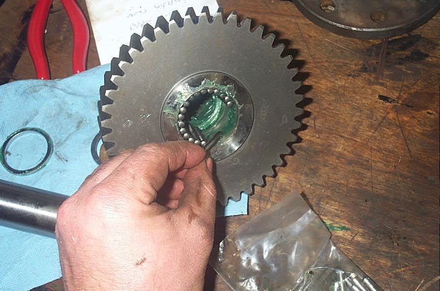 |
Install the needle bearings in the intermediate gear with grease. Note that there is a row of needle bearings on each side of the gear, with a bearing spacer / washer separating the 2 rows in the centre of the gear, as well as one on each side. | ||||||||||||||||||||||||||||||||||||||||||||||||||||||||||||||||||||||||||||||||||||||||||||||||||||||||||||||||||||||||||||||||||||||||||||||||||||||||
 |
Install the intermediate gear thrust washers in the case with heavy grease, being sure to align the tangs with the slots in the case. | ||||||||||||||||||||||||||||||||||||||||||||||||||||||||||||||||||||||||||||||||||||||||||||||||||||||||||||||||||||||||||||||||||||||||||||||||||||||||
 |
The installed thrust washers should look like this. | ||||||||||||||||||||||||||||||||||||||||||||||||||||||||||||||||||||||||||||||||||||||||||||||||||||||||||||||||||||||||||||||||||||||||||||||||||||||||
 |
Carefully drop the intermediate gear into place, being careful not to knock the needle bearings, bearing spacer washers or thrust washers out of place or alignment. It can be quite tricky and may take a few tries. I found it helpful to rotate the gear a little as I lowered it into place. | ||||||||||||||||||||||||||||||||||||||||||||||||||||||||||||||||||||||||||||||||||||||||||||||||||||||||||||||||||||||||||||||||||||||||||||||||||||||||
 |
Start intermediate gear shaft into case by hand. | ||||||||||||||||||||||||||||||||||||||||||||||||||||||||||||||||||||||||||||||||||||||||||||||||||||||||||||||||||||||||||||||||||||||||||||||||||||||||
 |
Once it begins to get tight, make sure the groove in the shaft faces the lock plate bolt hole. | ||||||||||||||||||||||||||||||||||||||||||||||||||||||||||||||||||||||||||||||||||||||||||||||||||||||||||||||||||||||||||||||||||||||||||||||||||||||||
 |
Then drive the shaft home with a brass or other soft drift. | ||||||||||||||||||||||||||||||||||||||||||||||||||||||||||||||||||||||||||||||||||||||||||||||||||||||||||||||||||||||||||||||||||||||||||||||||||||||||
 |
Install the lock plate... | ||||||||||||||||||||||||||||||||||||||||||||||||||||||||||||||||||||||||||||||||||||||||||||||||||||||||||||||||||||||||||||||||||||||||||||||||||||||||
 |
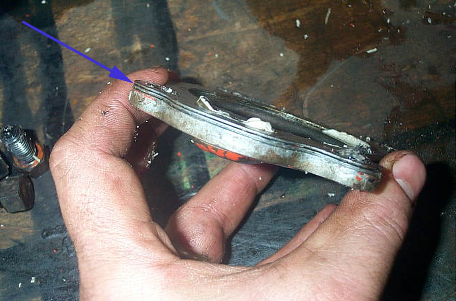
...and the transfer case tag and then install and tighten the lock plate bolt to 14 ft lbs. Check for clearance between the intermediate gear and the rear shift rod. Rotate the gear. If there is any contact seen, heard, or felt between the gear and the front shift rod, you will have to remove the shift rod and grind a little for clearance. |
||||||||||||||||||||||||||||||||||||||||||||||||||||||||||||||||||||||||||||||||||||||||||||||||||||||||||||||||||||||||||||||||||||||||||||||||||||||||
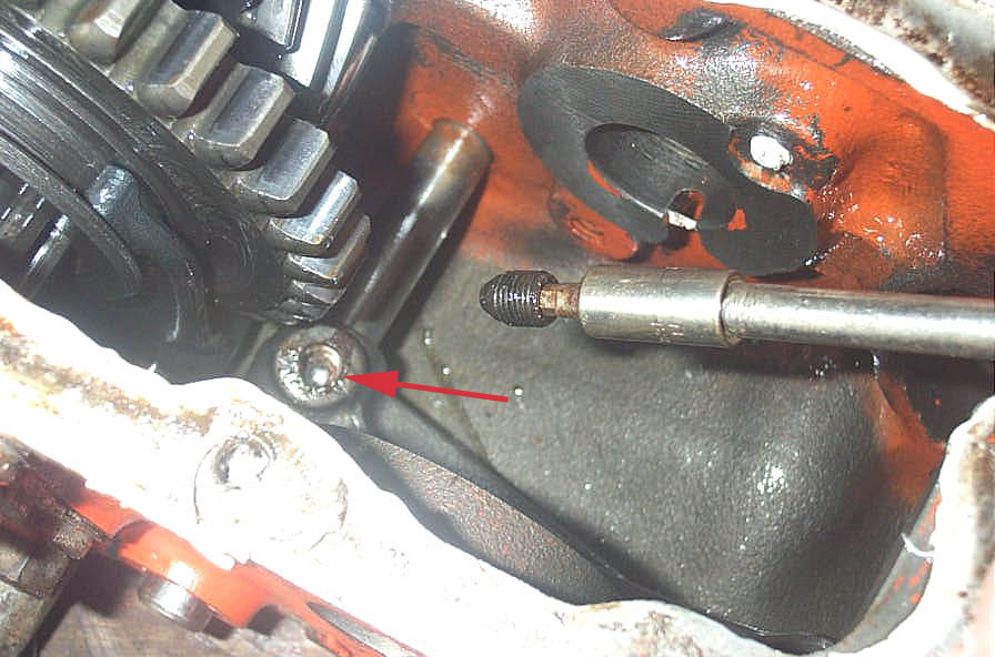
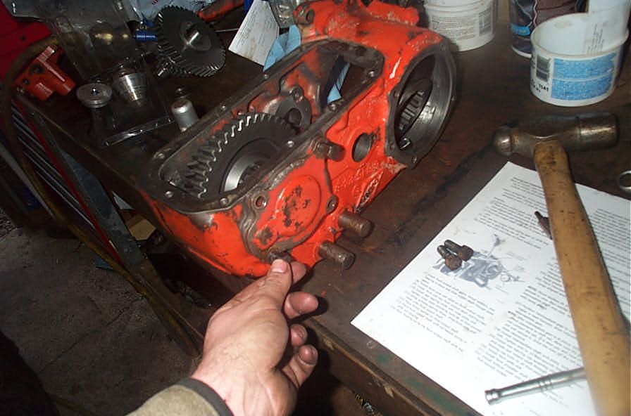
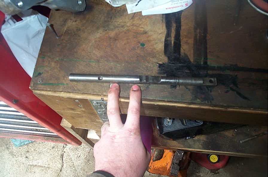 |
The area in question that will need to be clearanced is shown here between my fingers. | ||||||||||||||||||||||||||||||||||||||||||||||||||||||||||||||||||||||||||||||||||||||||||||||||||||||||||||||||||||||||||||||||||||||||||||||||||||||||
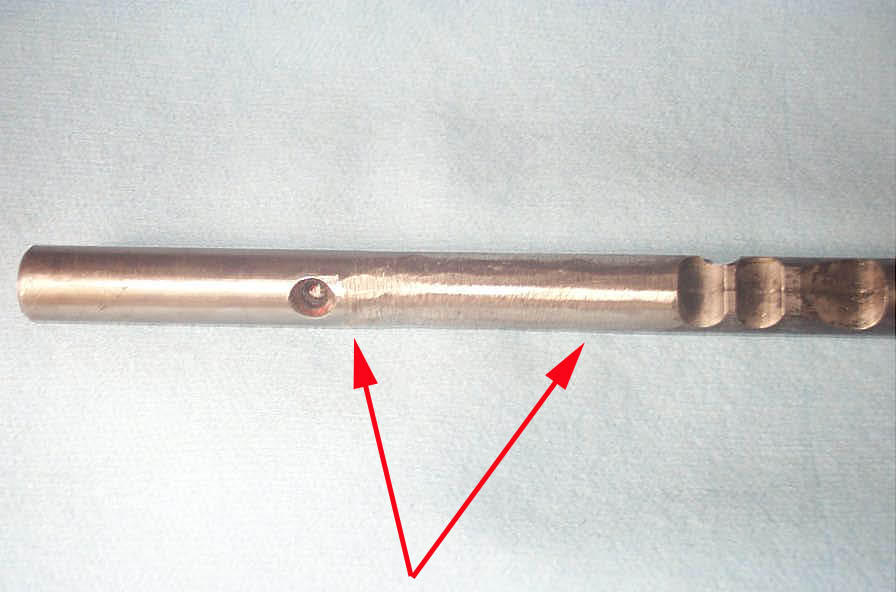 |
The red arrows show the are where I ground my shift rod slightly for clearance. | ||||||||||||||||||||||||||||||||||||||||||||||||||||||||||||||||||||||||||||||||||||||||||||||||||||||||||||||||||||||||||||||||||||||||||||||||||||||||
|
Coat rear output housing with RTV and install, tightening bolts to 30 ft lbs. | ||||||||||||||||||||||||||||||||||||||||||||||||||||||||||||||||||||||||||||||||||||||||||||||||||||||||||||||||||||||||||||||||||||||||||||||||||||||||
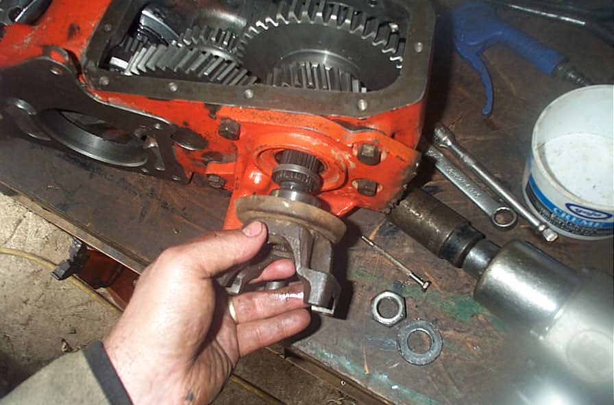 |
Install front output thrust washer and yoke. | ||||||||||||||||||||||||||||||||||||||||||||||||||||||||||||||||||||||||||||||||||||||||||||||||||||||||||||||||||||||||||||||||||||||||||||||||||||||||
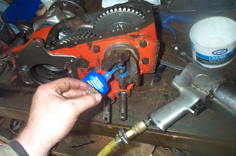 |
Apply thread locking compound. | ||||||||||||||||||||||||||||||||||||||||||||||||||||||||||||||||||||||||||||||||||||||||||||||||||||||||||||||||||||||||||||||||||||||||||||||||||||||||
 |
Tighten front output shaft yoke nut to 225-250 ft lbs. | ||||||||||||||||||||||||||||||||||||||||||||||||||||||||||||||||||||||||||||||||||||||||||||||||||||||||||||||||||||||||||||||||||||||||||||||||||||||||
|
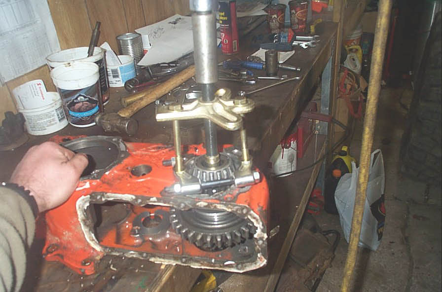
In my installation, the next thing I needed to do was install the doubler adapter with the main drive gear installed on it, back on the transfer case so I could turn the gears and check the case assembly and shifting operation before sealing up the case. | ||||||||||||||||||||||||||||||||||||||||||||||||||||||||||||||||||||||||||||||||||||||||||||||||||||||||||||||||||||||||||||||||||||||||||||||||||||||||
 |
This shot shows the poor, worthless quality of the Crown Automotive gaskets. Useless!! | ||||||||||||||||||||||||||||||||||||||||||||||||||||||||||||||||||||||||||||||||||||||||||||||||||||||||||||||||||||||||||||||||||||||||||||||||||||||||
 |
I'm not a big fan of gaskets anyway, and prefer a good, high quality RTV sealant / gasket making compound - but it's pretty poor when the bolt holes don't even line up. Like I said at the beginning - might as well just throw them out. | ||||||||||||||||||||||||||||||||||||||||||||||||||||||||||||||||||||||||||||||||||||||||||||||||||||||||||||||||||||||||||||||||||||||||||||||||||||||||
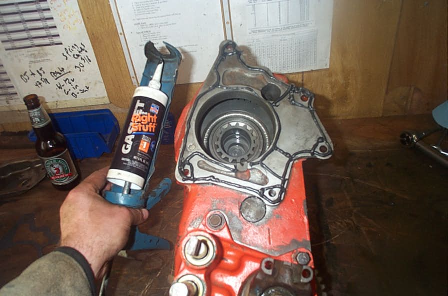 |
This is the stuff you want to use - either The Right Stuff, or the factory GM RTV - they are the best two gasketing products I have used . The last thing to do before bolting the lower cover back on and filling the case with 80w90 gear oil is to check the operation. |
||||||||||||||||||||||||||||||||||||||||||||||||||||||||||||||||||||||||||||||||||||||||||||||||||||||||||||||||||||||||||||||||||||||||||||||||||||||||
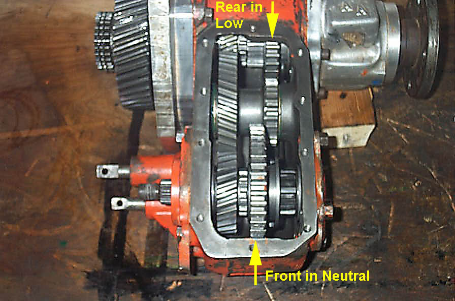
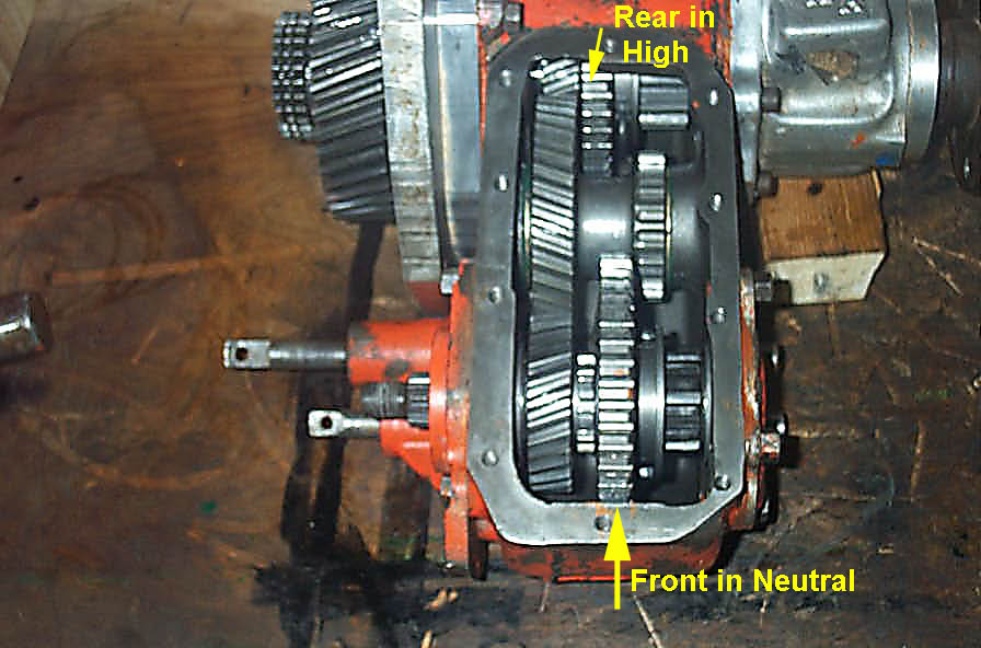
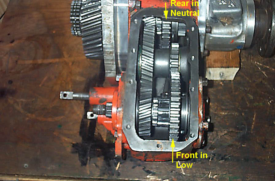
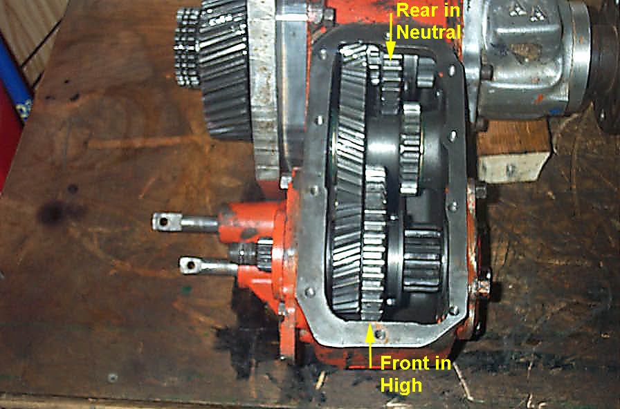
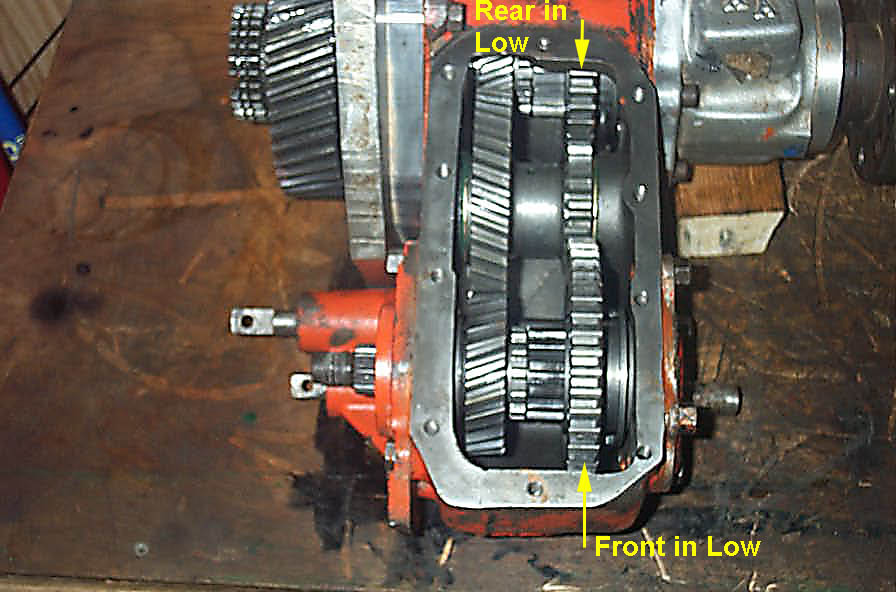
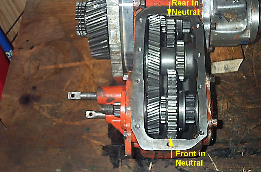
Checking Case OperationTo check the case operation and ensure that you have all the parts in the right place, proceed as follows:
|
|||||||||||||||||||||||||||||||||||||||||||||||||||||||||||||||||||||||||||||||||||||||||||||||||||||||||||||||||||||||||||||||||||||||||||||||||||||||||
|
Once you are done with checking, install the lower cover using RTV and torque the cover bolts to 15 ft lbs. | ||||||||||||||||||||||||||||||||||||||||||||||||||||||||||||||||||||||||||||||||||||||||||||||||||||||||||||||||||||||||||||||||||||||||||||||||||||||||
Installing the case in the vehicle |
|||||||||||||||||||||||||||||||||||||||||||||||||||||||||||||||||||||||||||||||||||||||||||||||||||||||||||||||||||||||||||||||||||||||||||||||||||||||||
 |
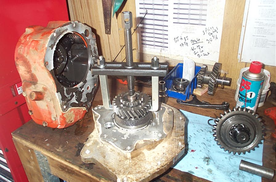
This was probably the hardest part of the whole project. Here you can see my complete doubler transfer case assembly ready to be installed - it's one heavy SOB, and pretty tricky to get in place, lined up, and the bolts all started without cross-threading!. As with all the other mating surfaces, you must gasket the transfer case to transmission joint. This was the one place where a decent gasket would be helpful, as it would prevent inadvertent smearing of RTV as you jack, strap, and struggle to get the case installed and lined up. |
||||||||||||||||||||||||||||||||||||||||||||||||||||||||||||||||||||||||||||||||||||||||||||||||||||||||||||||||||||||||||||||||||||||||||||||||||||||||
 |
I ended up having to cut a hole in the floor... | ||||||||||||||||||||||||||||||||||||||||||||||||||||||||||||||||||||||||||||||||||||||||||||||||||||||||||||||||||||||||||||||||||||||||||||||||||||||||
 |
...then putting one strap around the roof of the Wolf, with another ratcheting strap extending vertically from there, through the hole in the floor, to a chain wrapped around the transfer case. | ||||||||||||||||||||||||||||||||||||||||||||||||||||||||||||||||||||||||||||||||||||||||||||||||||||||||||||||||||||||||||||||||||||||||||||||||||||||||
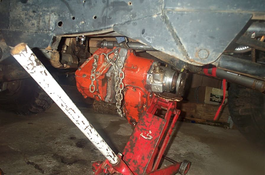 |
Then with a floor jack on the output housing for additional support and to help clock the case to the right position, I was able to get it all lined up and installed. | ||||||||||||||||||||||||||||||||||||||||||||||||||||||||||||||||||||||||||||||||||||||||||||||||||||||||||||||||||||||||||||||||||||||||||||||||||||||||
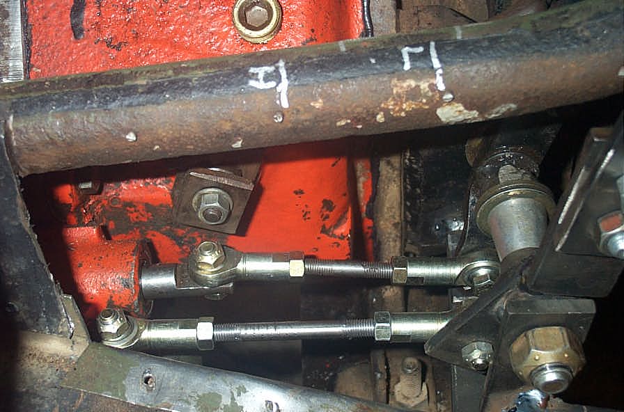 |
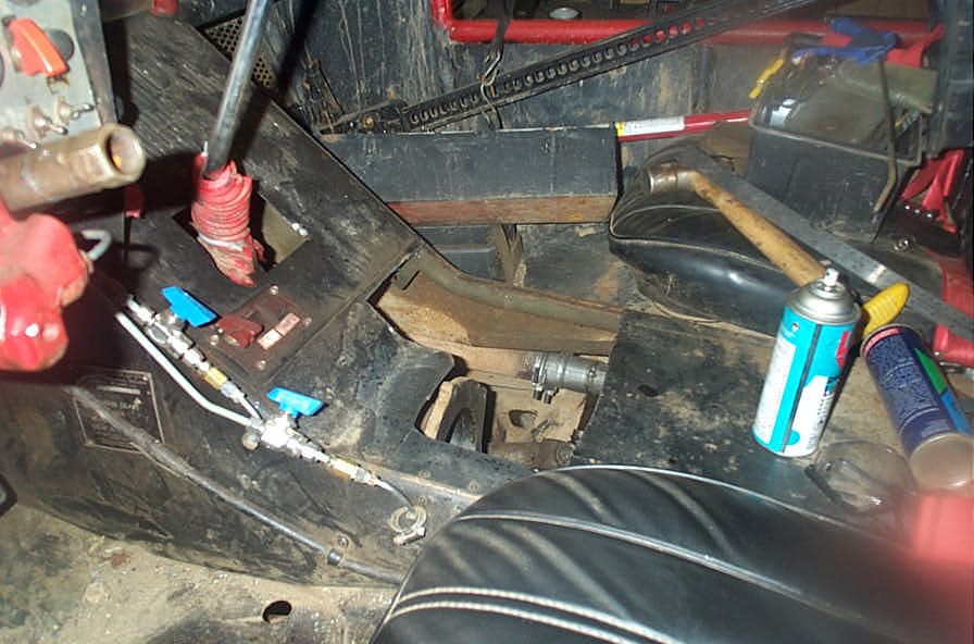
Detail of my home-brew shift linkage. This pic illustrates how, when you shift the lever forward, you are actually shifting the shift rod to the rear. | ||||||||||||||||||||||||||||||||||||||||||||||||||||||||||||||||||||||||||||||||||||||||||||||||||||||||||||||||||||||||||||||||||||||||||||||||||||||||
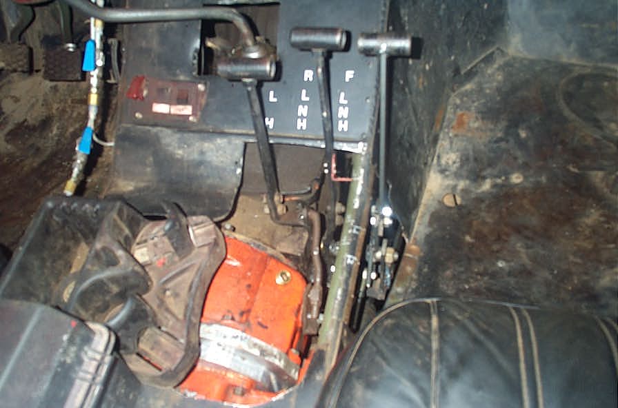 |
From left to right are:
Note that if you remove the interlock pill and twin-stick your case, there is the possibility to shift one axle into low gear and the other into high at the same time. This will quickly cause serious drivetrain damage (although I did try it briefly on a soft, loose surface, just to see what it was like.) Some folks may decide to rig up some sort of extra mechanism to allow twin -stick shifting while preventing the levers from being more than one position apart. I didn't bother, as the shift pattern arrangement would mean that to inadvertently shift into low-high or high-low, one stick has to be all the way forward, and one all the way to the rear - which is really obvious, and hard to do accidentally. Also - if the rig is in low-high or high-low, it's VERY obvious as it hops and spins and churns in a very unusual manner. |
||||||||||||||||||||||||||||||||||||||||||||||||||||||||||||||||||||||||||||||||||||||||||||||||||||||||||||||||||||||||||||||||||||||||||||||||||||||||
ResultsThe most important part - what are the results of this upgrade? What you gain is:
But the greatest improvement relates back to what I was saying at the beginning about "gear stepping" or "ratio spanning". Recall my original gear table:
What I was really missing was a gear between my low / low and the next lowest gear. That is, something between 59 and 107, as well as something between the next 2 gears i.e. (29 and 54). I knew this just from driving the rig - even before charting the math involved. In other words, my lowest gears (deeper than about 25:1 which is what I use most on the trail) used to be 27, 29, 54, 59, 107. Now I have 27, 29, 41, 46, 54, 85, 92, 169 You just don’t get choices like that with a fancy aftermarket transfer case. If I had, for example a 4.3 low ratio Atlas II, I would have: 27, 28, 63, 115, or in effect, only 3 really usable gear ratios, for twice the price. To me, that is far from the ideal setup. In my opinion, it’s all about 3 things: - Options for different terrains Judged by that criteria, and by real world budget constraints, with the option of building over time, the low buck doubler with aftermarket gears in one transfer case comes out as an awesome option - and one I am extremely pleased with and don't regret one bit. Testing |
|||||||||||||||||||||||||||||||||||||||||||||||||||||||||||||||||||||||||||||||||||||||||||||||||||||||||||||||||||||||||||||||||||||||||||||||||||||||||
 |
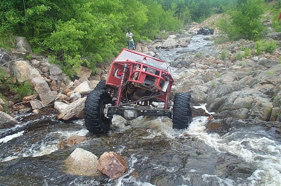
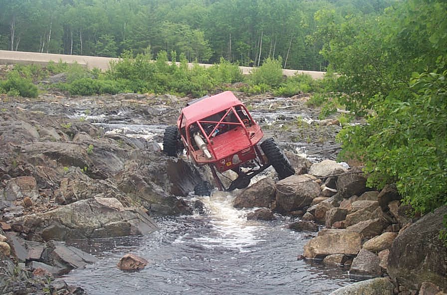
The rig is now much more of a pleasure to drive. Whether you're driving a performance car, a rock buggy, or pedalling a bicycle - huge jumps in gear ratio suck! | ||||||||||||||||||||||||||||||||||||||||||||||||||||||||||||||||||||||||||||||||||||||||||||||||||||||||||||||||||||||||||||||||||||||||||||||||||||||||
 |
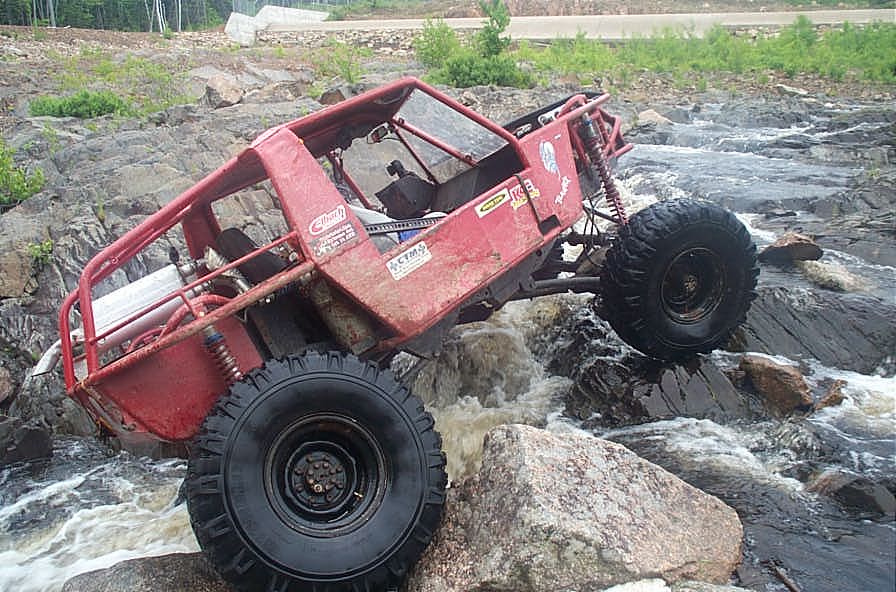
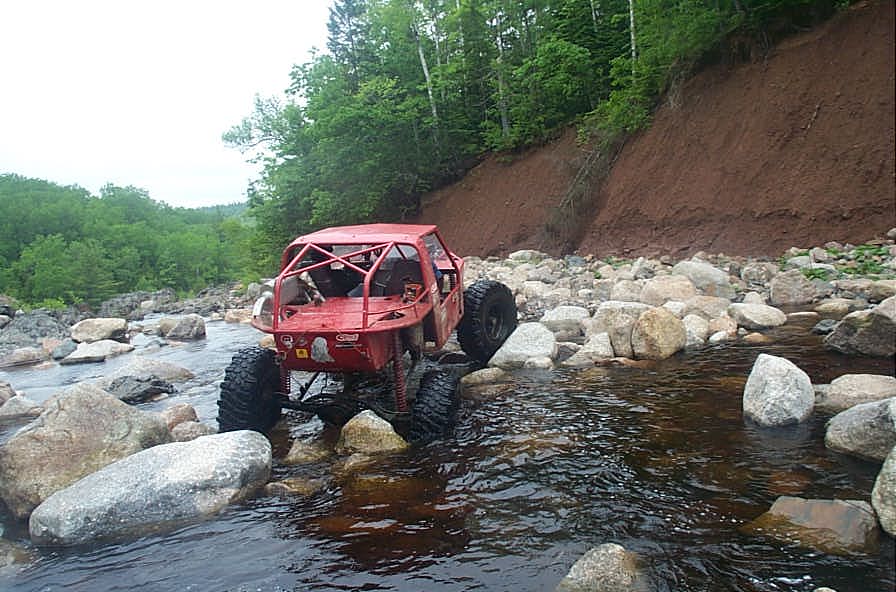
In the kind of rocky, slippery terrain I prefer, shown here, the extra gears, and especially the way low 169:1 give me great improvement in control and drivability. | ||||||||||||||||||||||||||||||||||||||||||||||||||||||||||||||||||||||||||||||||||||||||||||||||||||||||||||||||||||||||||||||||||||||||||||||||||||||||
References: |
|||||||||||||||||||||||||||||||||||||||||||||||||||||||||||||||||||||||||||||||||||||||||||||||||||||||||||||||||||||||||||||||||||||||||||||||||||||||||
|
Sources: Tera Manufacturing, Inc. 5251 South Commerce Dr.
|
|