| |
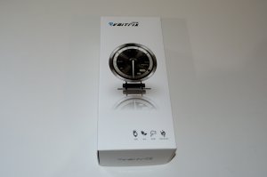 |
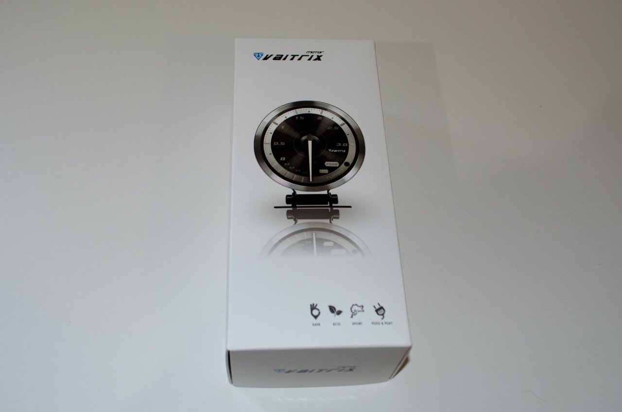
The Vaitrix gauge is an attractive, high-quality gauge. Everything required comes in the box except... |
| |
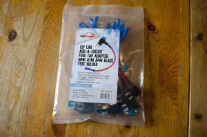 |
...you will also need two "fuse taps" or "add a fuses". I bought this pack from Amazon. |
| |
 |
Inside the Vaitrix box we have:
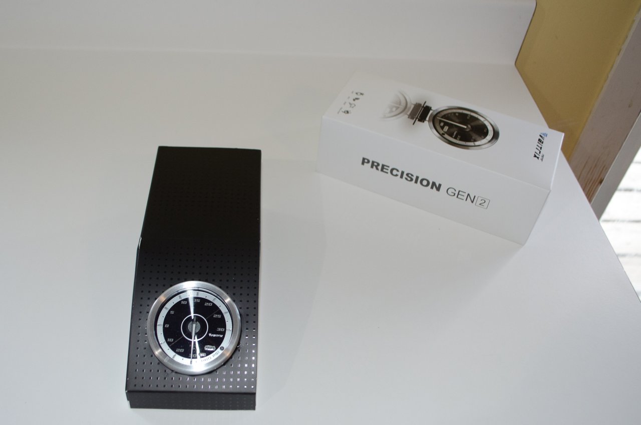
The gauge itself. |
| |
 |
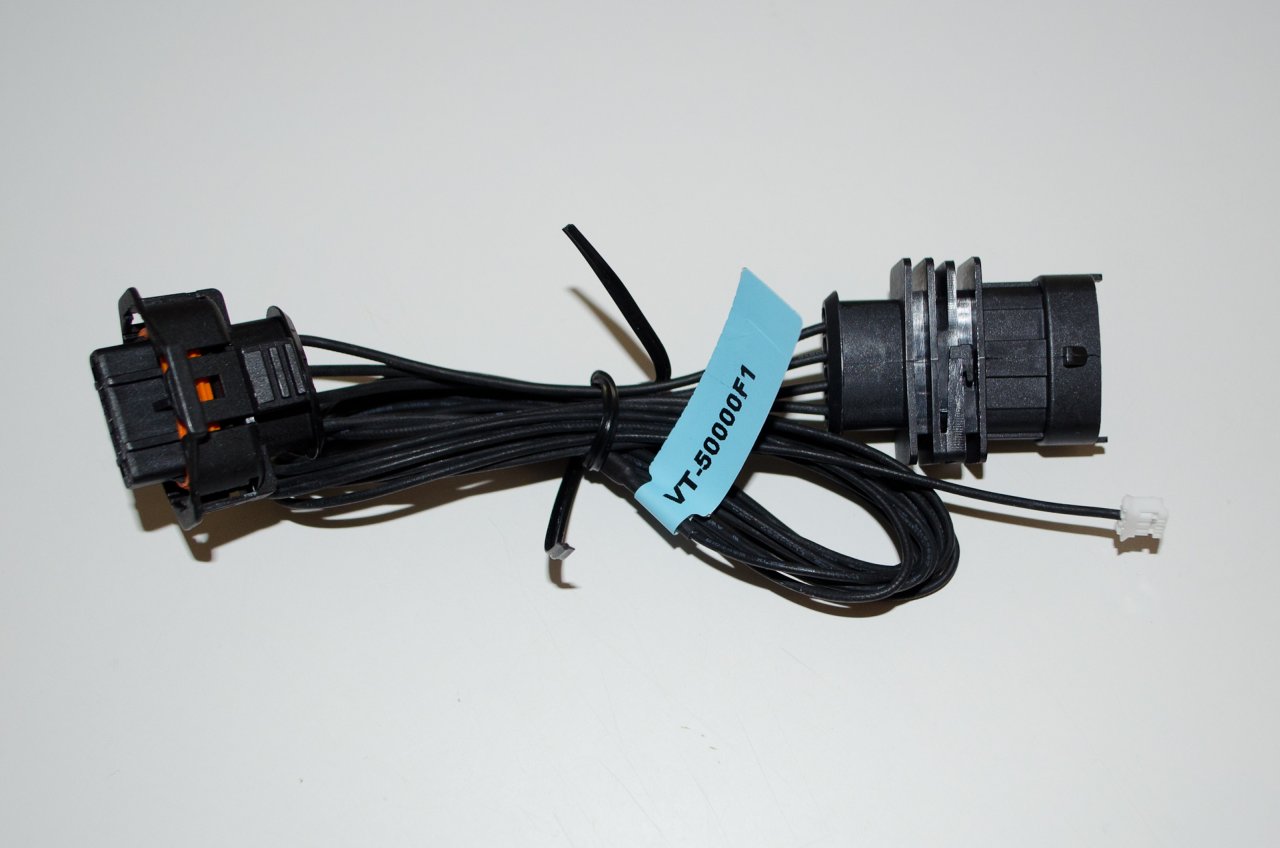
The sensor wiring harness. |
| |
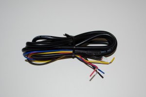 |
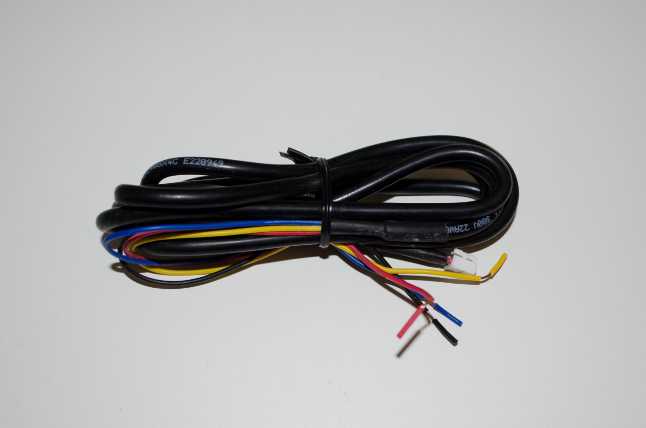
The power supply wiring harness. |
| |
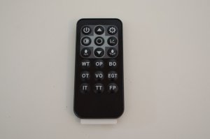 |
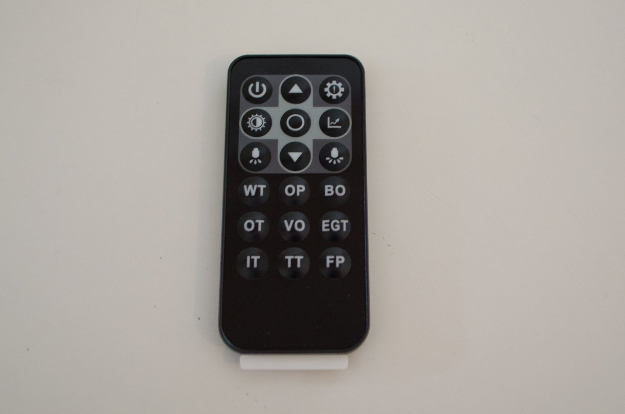
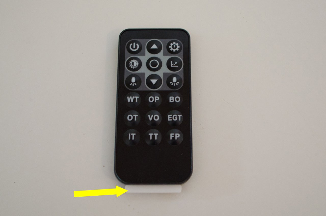
A small remote control for programming the max. boost alert, recalling peak boost, and adjusting the lighting level of the gauge. |
| |
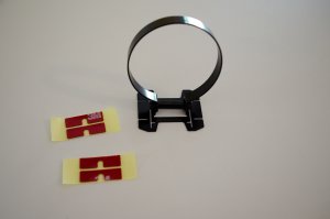 |
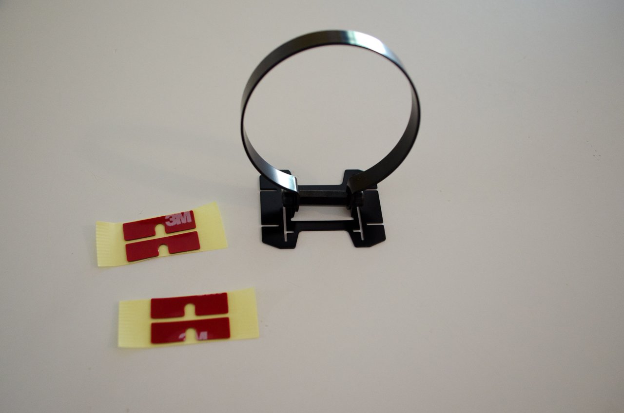
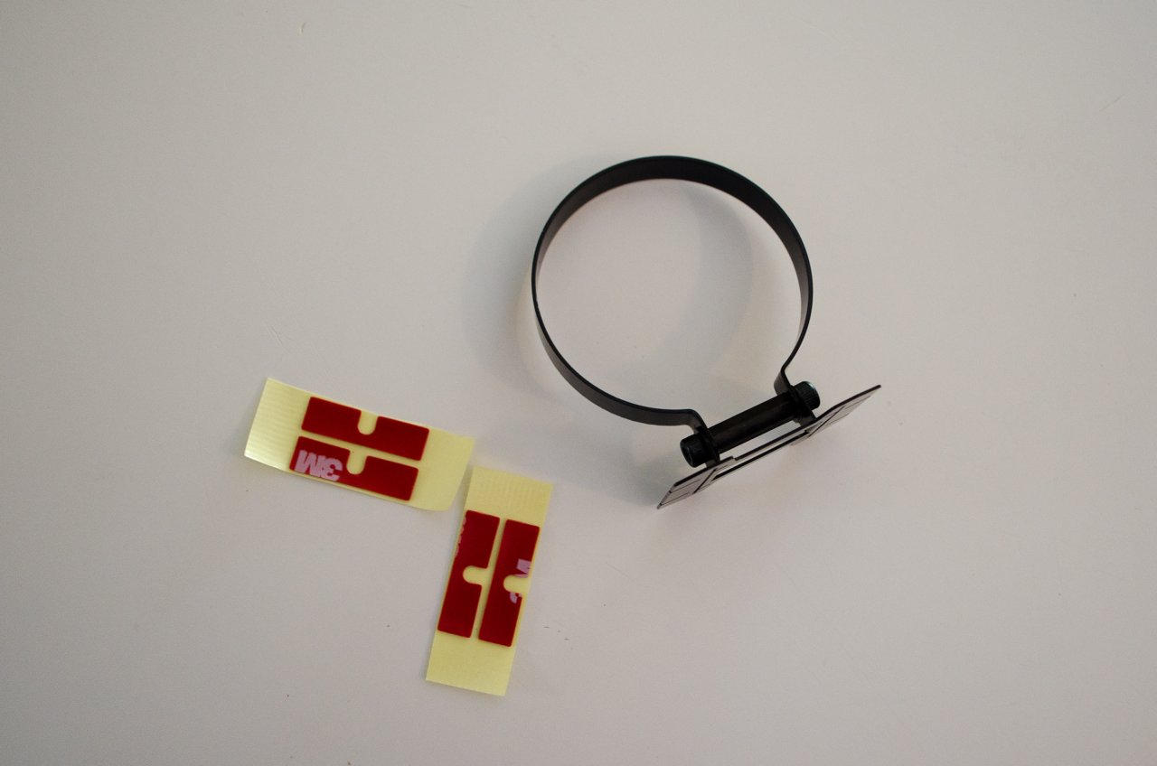
A mounting bracket with some 3M double-sided tape. |
| |
 |
While flexible, the supplied mounting bracket is my least favourite part of the kit...more on this later. |
| |
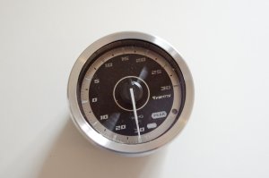 |
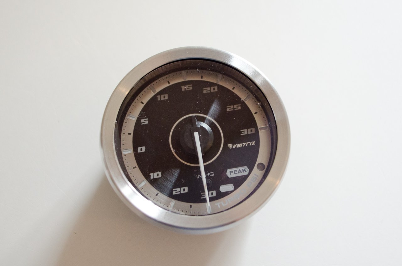
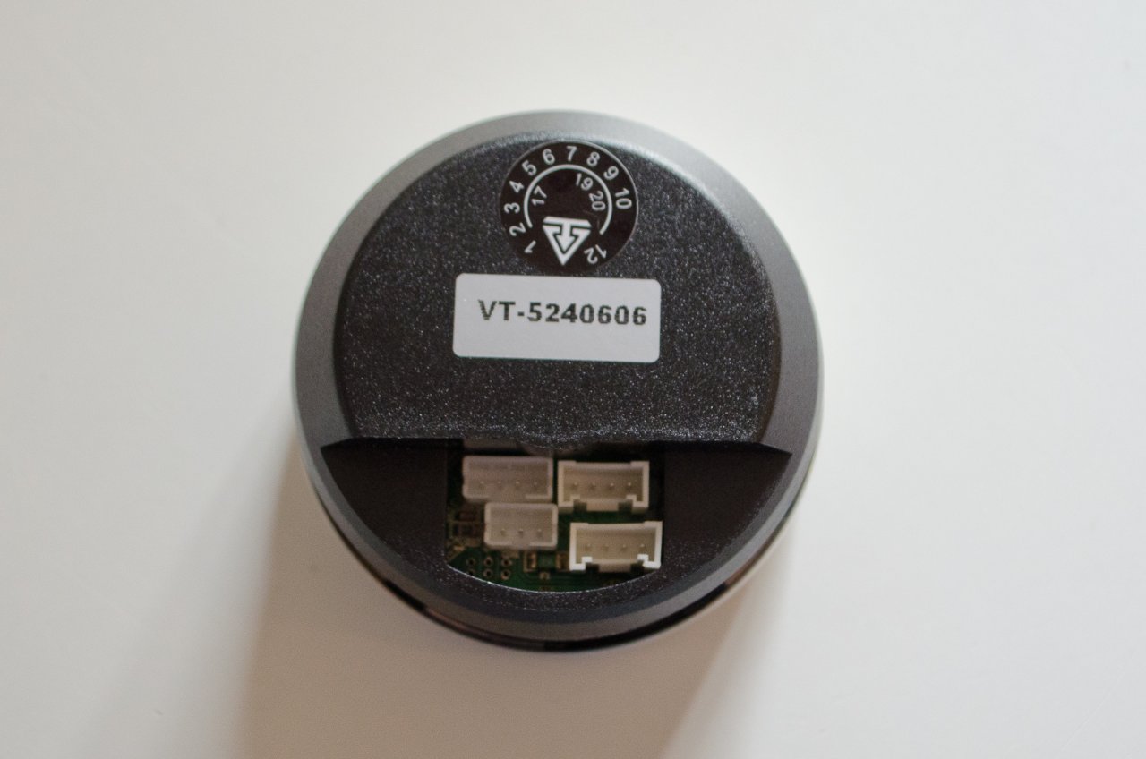
The gauge I chose goes up to 30 psi, and has a classic look and feel. This photo really doesn't do it justice (note also that the plastic lens protector is still in place in this pic). |
| |
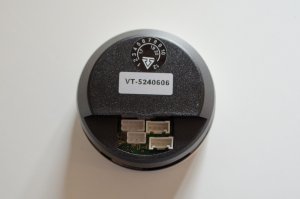 |
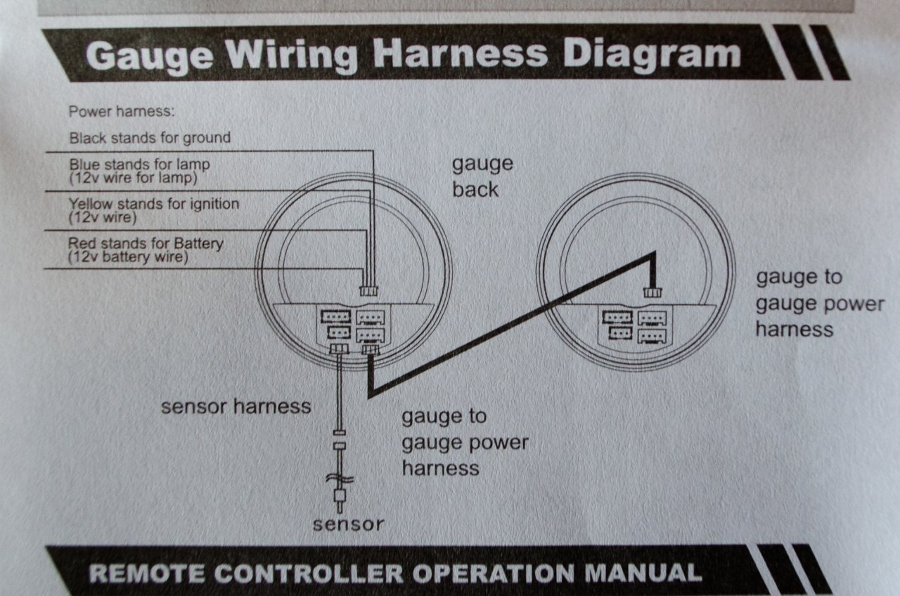
There are four connections on the back, but only two are used in this installation...more on this later. |
| |
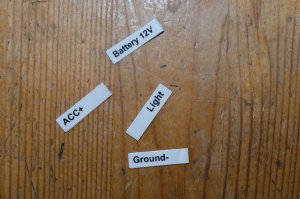 |
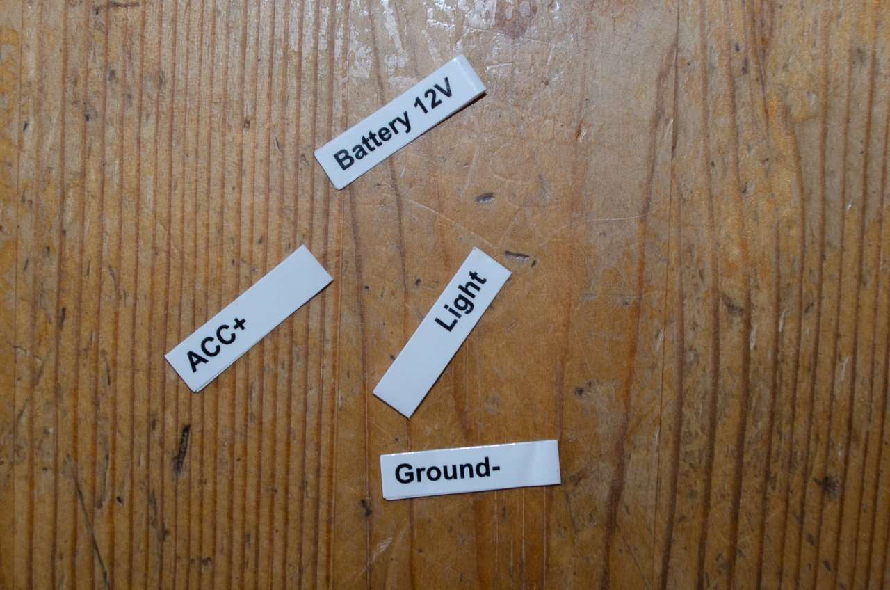
Loose in the bottom of the box there were these small labels. I'm not sure if they fell off or are intended to be user-applied. In any case, I did not use them as we are only going to use 3 wires in this installation and they are all industry-standard colours...more on this later. |
| |
 |
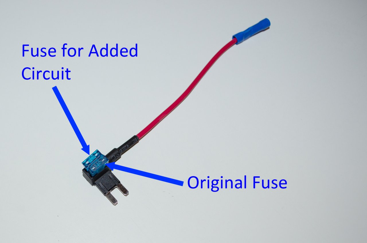
This is the fuse tap. It can be used either in an empty fuse slot, or you can remove an existing fuse, insert the tap, and re-use the existing fuse and a new fuse for the gauge. We'll see exactly how it works and how to use it shortly. |
| |
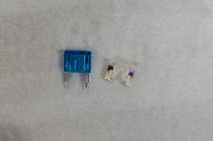 |
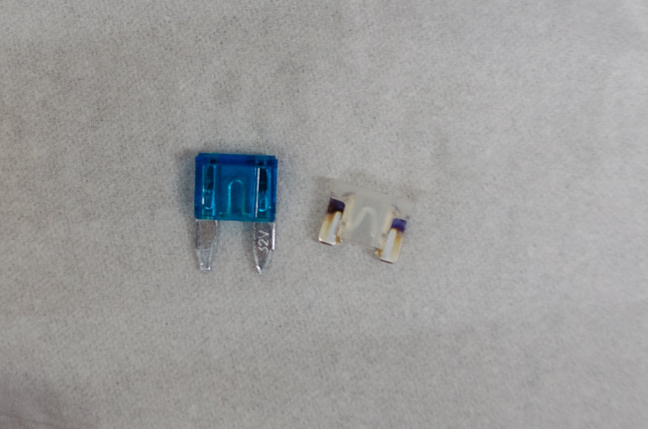
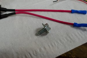
Of note, the pack of fuse taps I bought came with mini-ATC fuses (blue fuse, left) while the 124 Spider uses low-profile mini-ATC fuses (white fuse, left).
For this job it still worked with the supplied mini-ATC fuses, but sourcing low-profile fuses would make for a neater, tidier installation. |
| |
 |
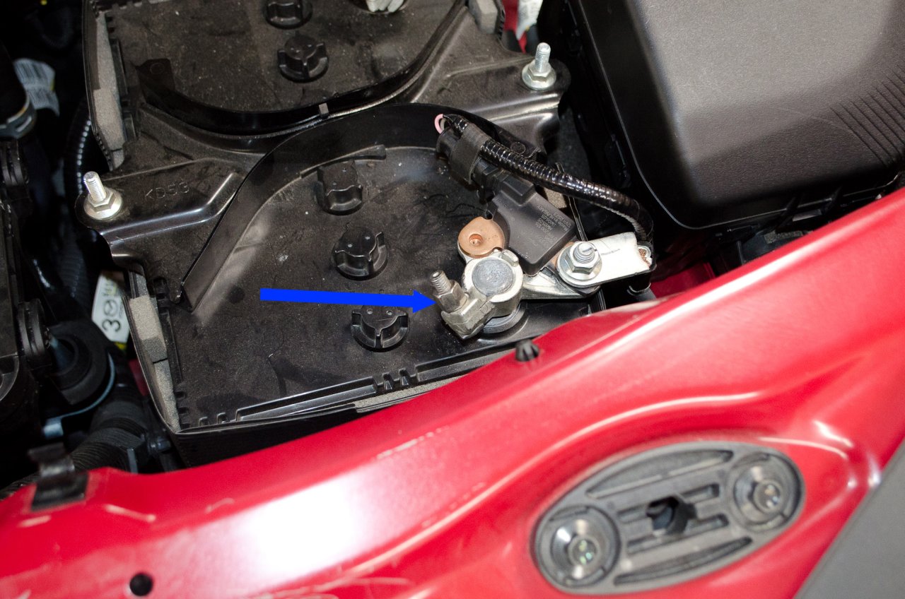
As with any job involving electrical circuits, begin by disconnecting the battery's negative terminal.
It takes a 10mm wrench. |
| |
 |
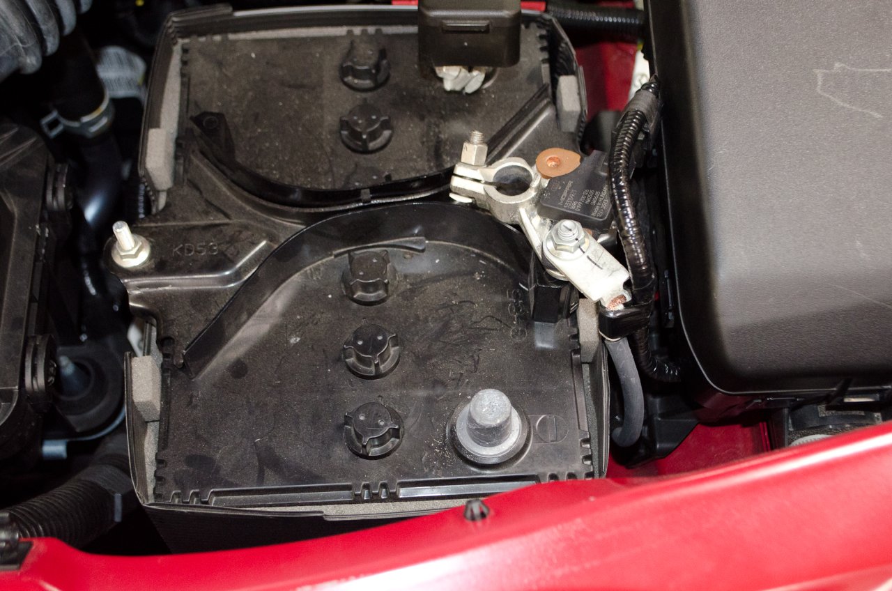
Like so. |
| |
 |
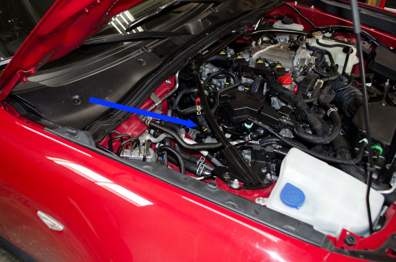
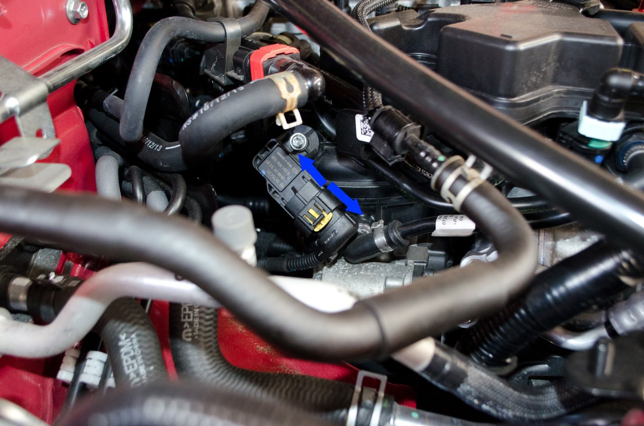
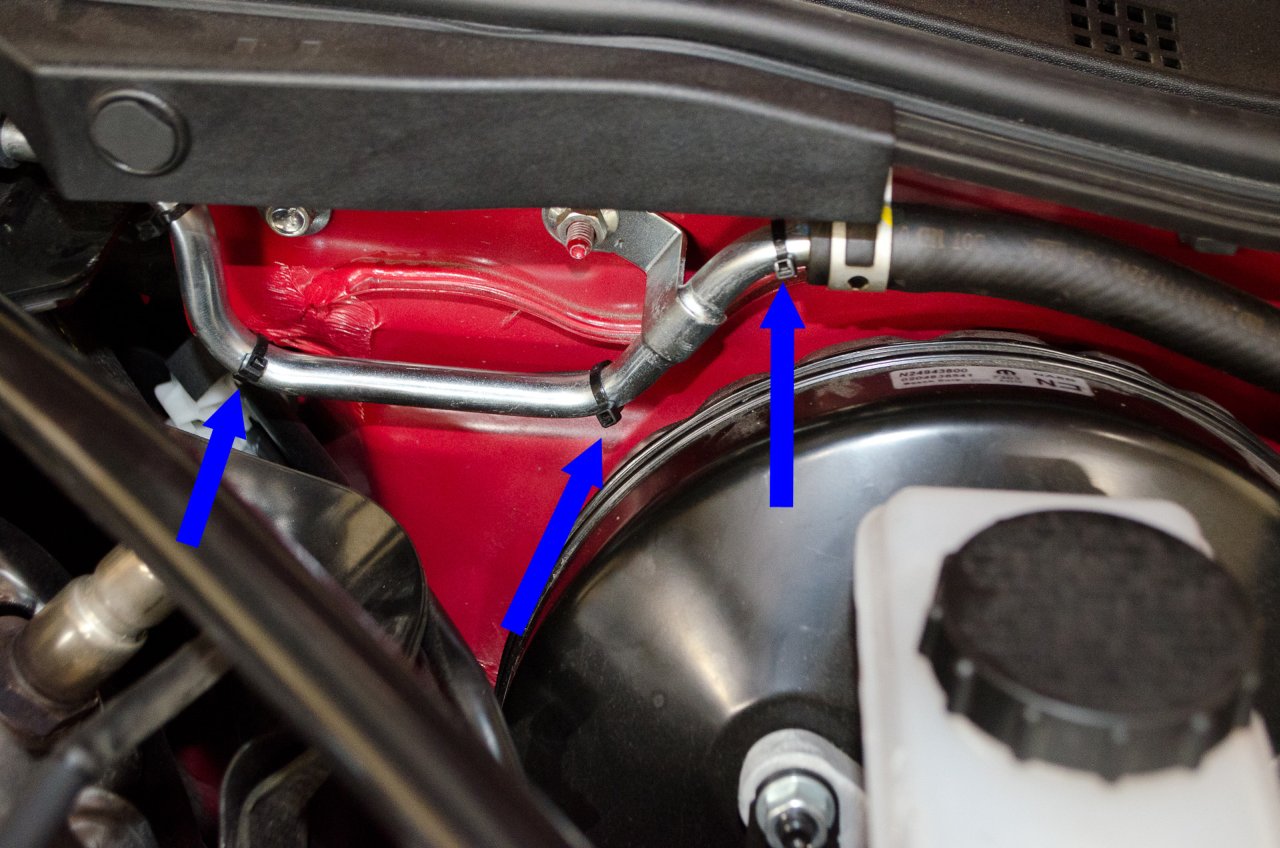
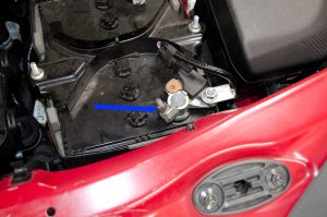
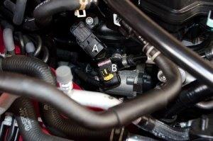
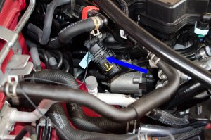
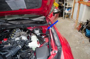
Next, locate the intake air
temperature/pressure sensor on the right side of the engine bay (blue arrow). |
| |
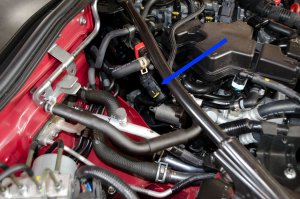 |
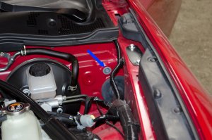
Closer view. |
| |
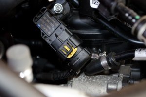 |
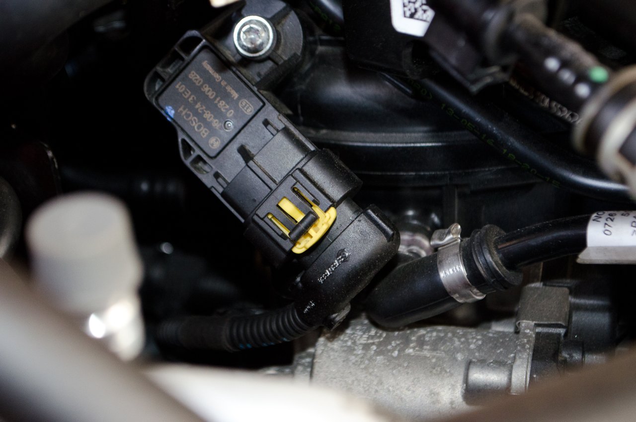
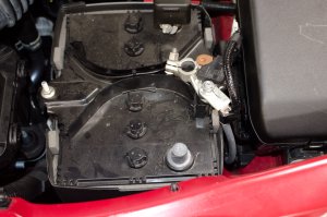
Intake air
temperature/pressure sensor. |
| |
 |
We are going to disconnect the factory wiring from the sensor, and connect the boost gauge sensor harness in line (in series) with the factory sensor and wiring. |
| |
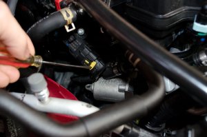 |
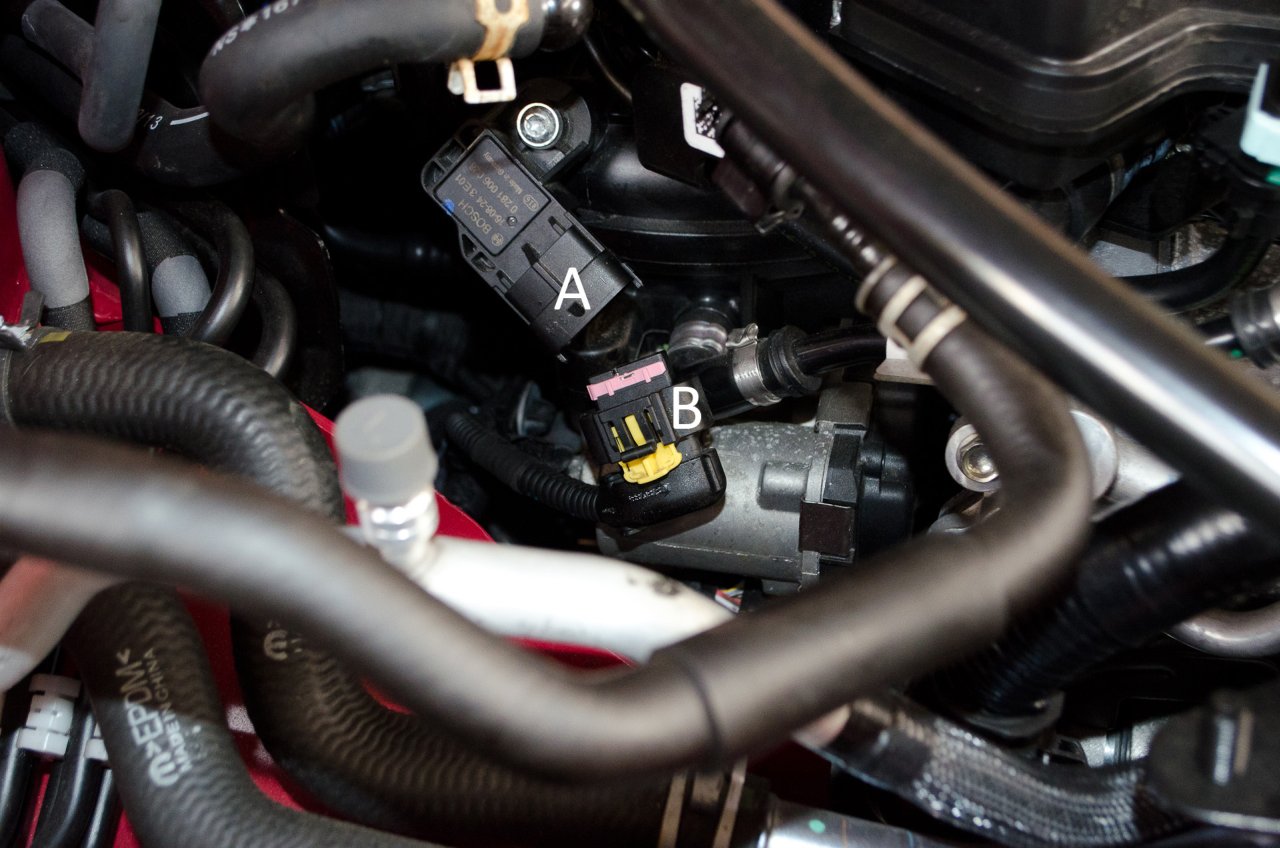
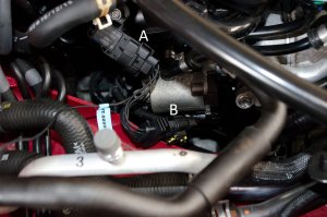
First, release the yellow locking clip by pressing down with a small screwdriver... |
| |
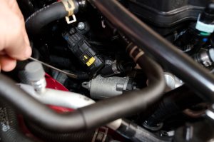 |
...until it is extended or "unlocked", like this. |
| |
 |
Then press down on the black lever/tab and gently separate the wiring plug (B) from the sensor (A), like this. |
| |
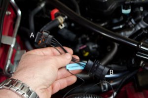 |
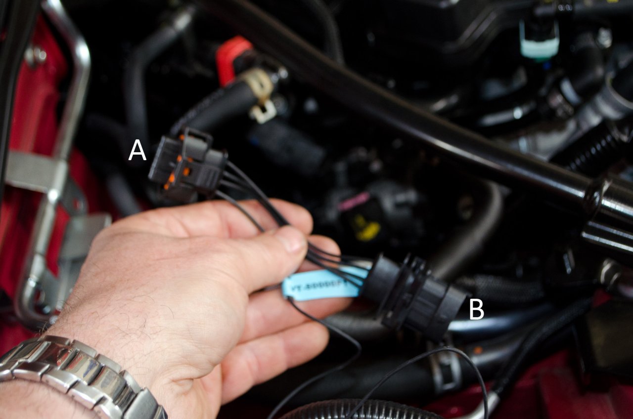
The Vaitrix sensor harness only fits one way. The "male" end (labelled (A) here) plugs into the sensor in the car, and into the female end (B) we plug the factory wiring plug we just disconnected. |
| |
 |
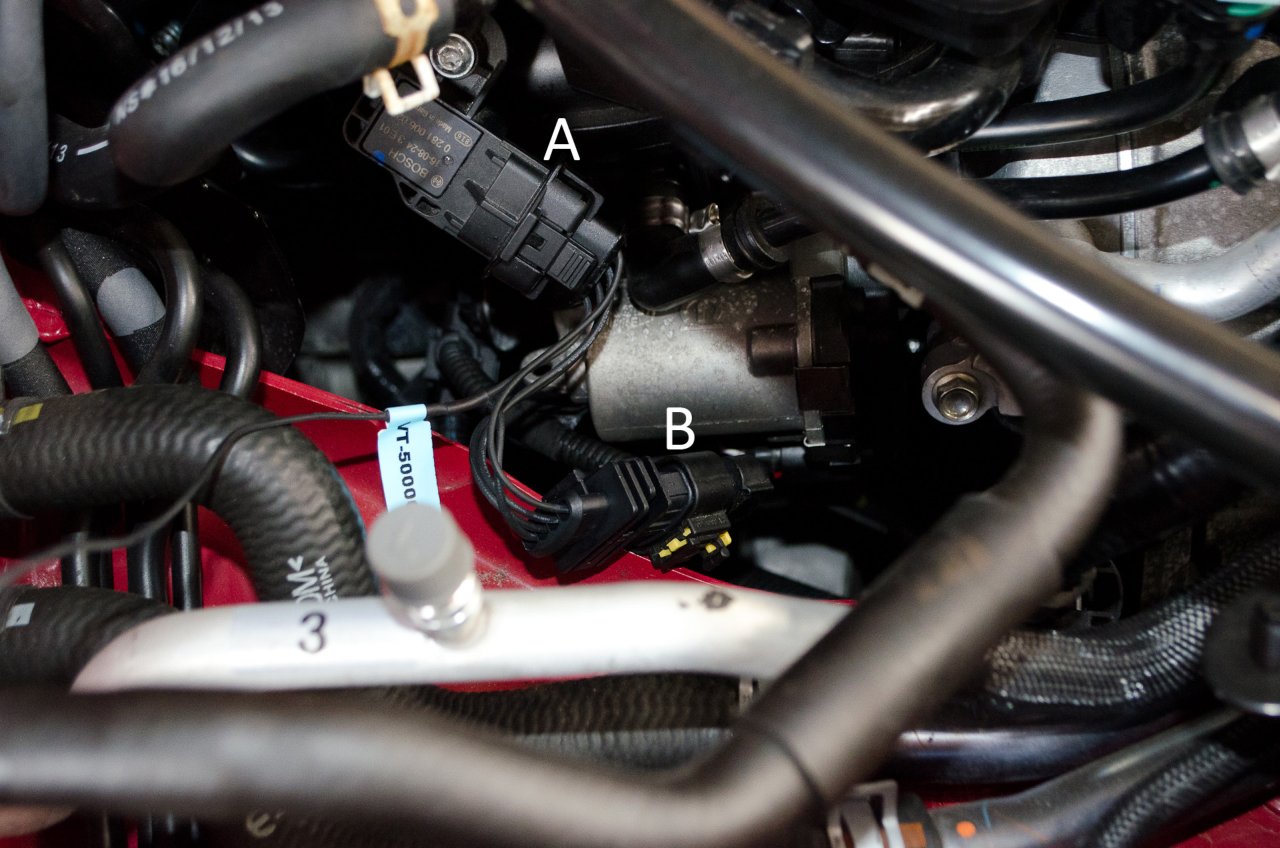
Like so.
Remember to engage the yellow locking tab in the up or "locked" position when done. |
| |
 |
I used a small zip tie to keep everything secured. |
| |
 |
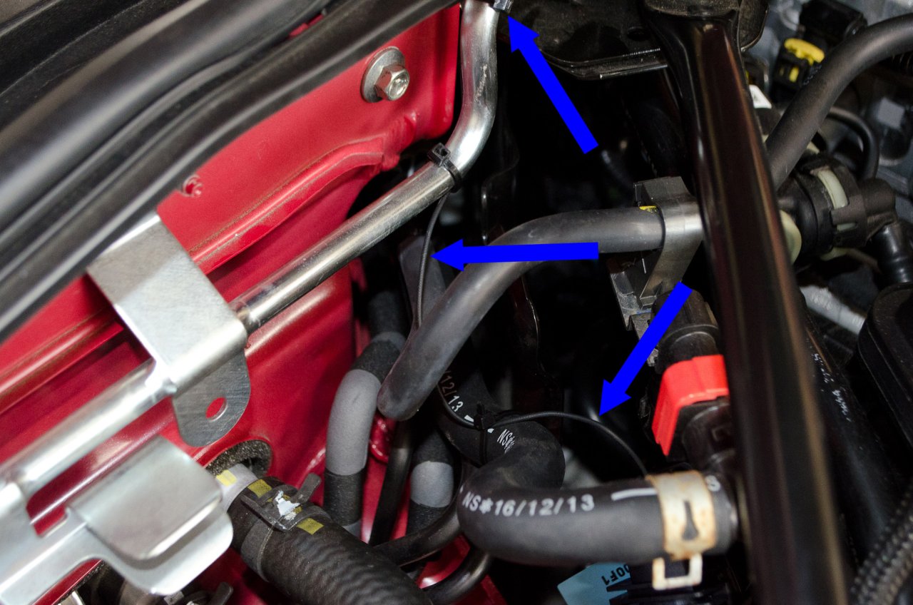
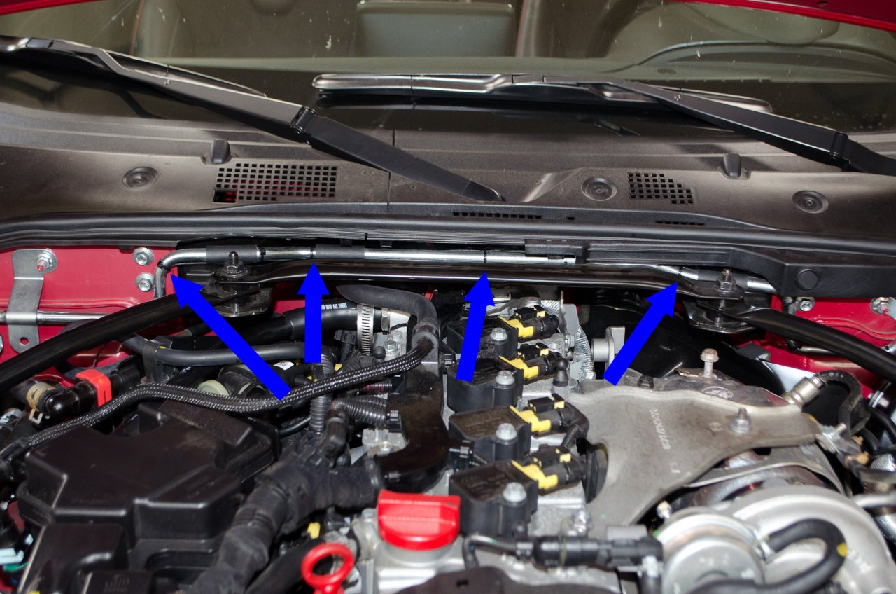
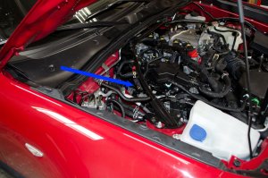
You now have to route the Vaitrix sensor wire into the cabin where it can plug into the gauge on the dash.
I routed mine back to the firewall and along the back of the steel brake booster vacuum line over to the left side of the engine bay. |
| |
 |
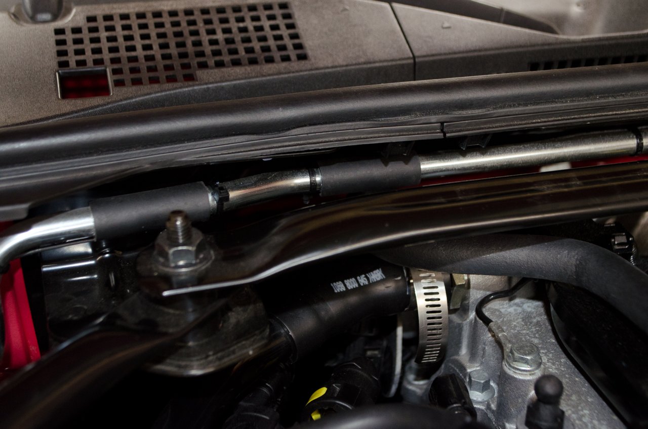
Details of the routing I chose. |
| |
 |
I wanted a nice clean install without loose wires hanging down or flopping about. |
| |
 |
I used plenty of small zip ties to keep it secure. |
| |
 |
Closer view. |
| |
 |
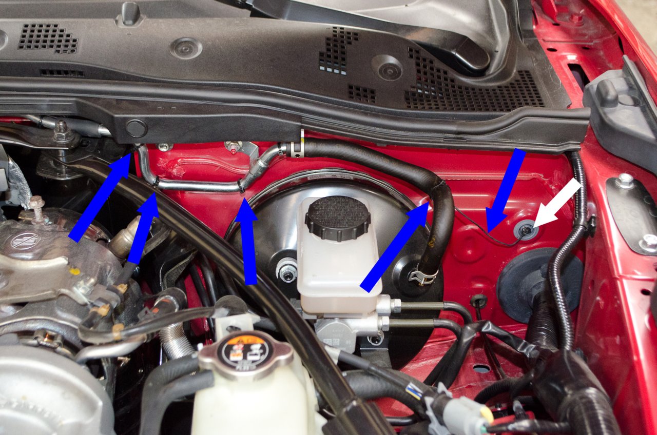
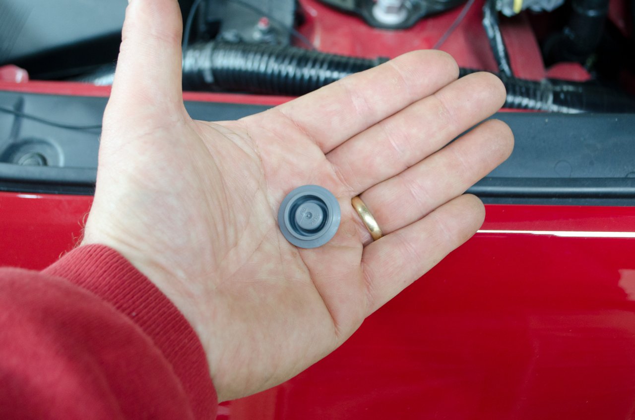
To get it into the cabin, we're going to go through this little grommet here. |
| |
 |
Closer view. |
| |
 |
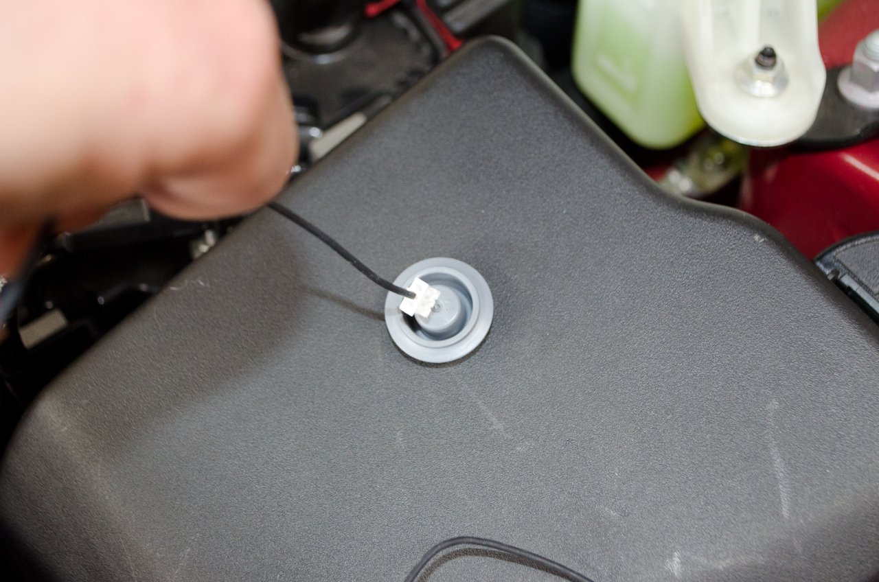
We're going to remove the grommet, cut a slit or hole in it, reinstall it, and then pass the sensor wire through it. |
| |
 |
To avoid scratching the paint trying to lever the grommet out from under the hood, I placed a loose piece of tape over it from under the hood, then went inside the car and up under the dash above the driver's footwell and simply pressed it out from the inside out.
The tape helps prevent it from shooting out and/or falling in to the abyss of the engine bay. |
| |
 |
The plug on the end of the sensor cable is almost the same size as the center-piece of the grommet.
I initially tried just cutting a slot, hoping to slip the plug through, but found the plastic of the grommet too hard for this approach to work, so I ended up cutting a decent size hole in the grommet with a sharp utility knife so I could get the plug through without damaging it. |
| |
 |
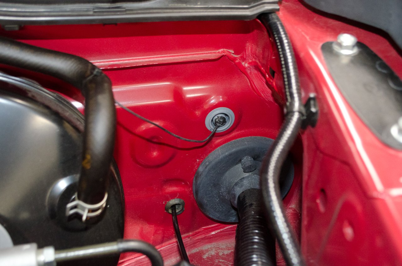
After passing the wire through, I sealed it with a dab of RTV sealant. |
| |
 |
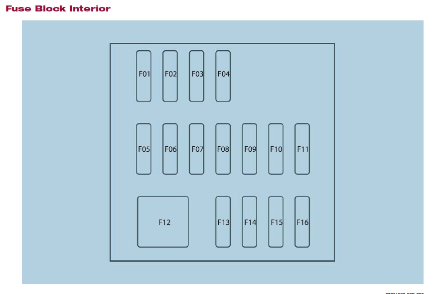
With sensor wire in place, it's time to move on to the power wiring harness for the gauge.
As mentioned, we're going to tap into the interior fuse block using two fuse taps to get the power we need - 12V+ battery power (i.e. always on) and 12V+ ignition switched power (i.e. powered when the car's electrical power is turned on).
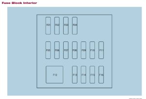
This is the map of the interior fuse block.
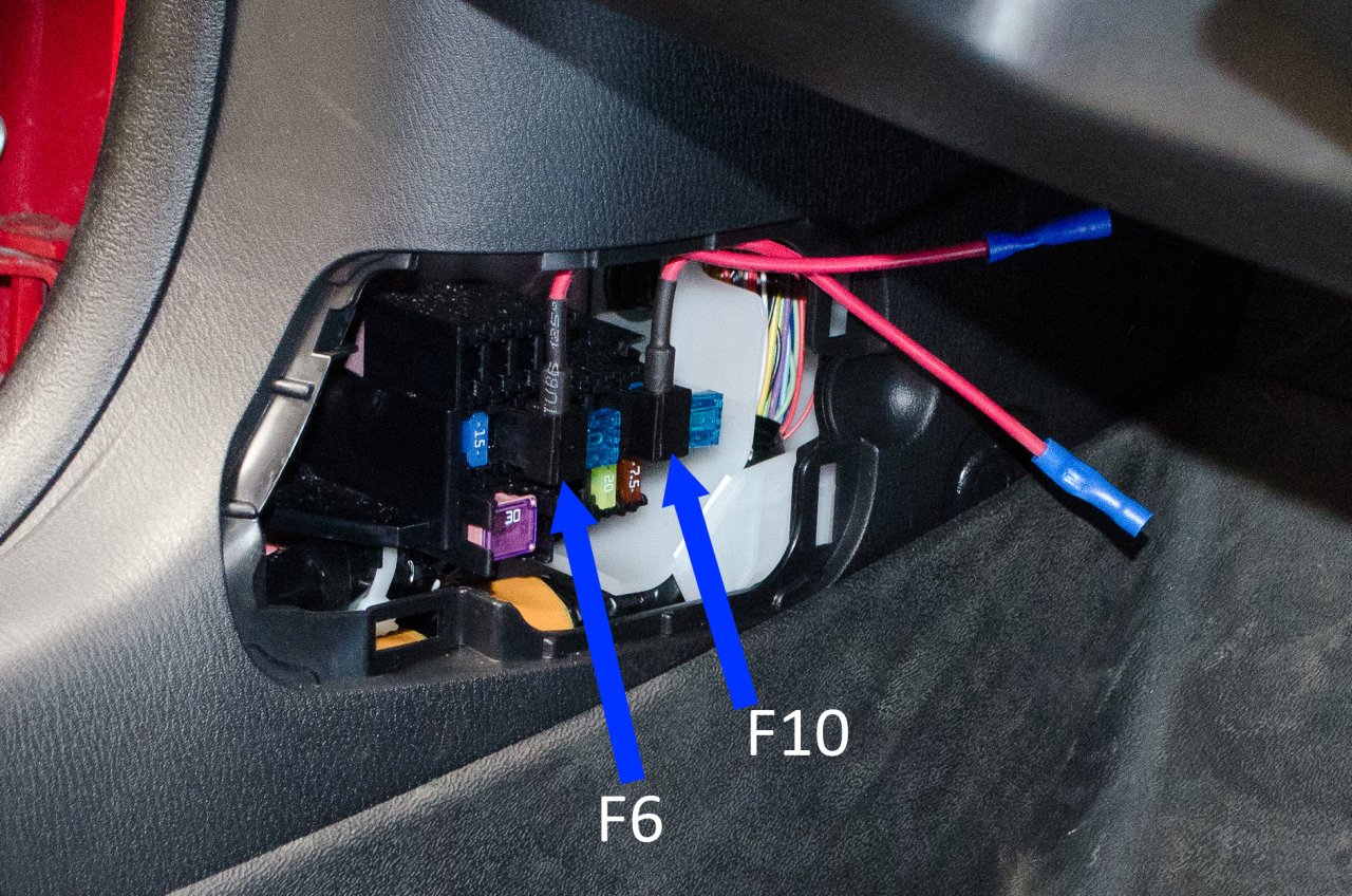
I used slots F6 and F10, both of which were empty. |
| |
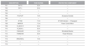 |
F6 supplies the 12V+ ignition switched power.
F10 supplies 12V+ battery power.
If your car has different options, you may not have the same slots free so you may have to use the fuse taps to power the original circuit as well as the boost gauge, so lets look at how the fuse taps work so you can easily use them either way - in an empty slot or in an occupied slot. |
| |
 |
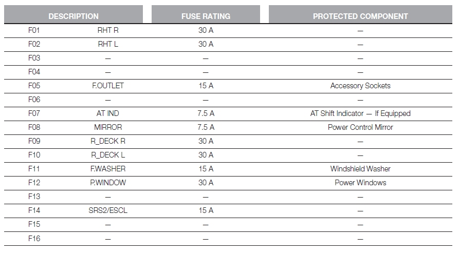
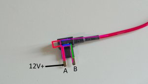
The premise is, you remove an existing fuse, plug that removed fuse and an appropriate fuse for the new circuit into the device, and then plug the device into the slot from which you removed the fuse...and use the pigtail wire on the device to power your new circuit.
But to use it correctly, it has to be plugged in in the right orientation.
The red line indicates that, with no fuses installed, terminal (or leg) A is connected to BOTH of the two slots above it, while terminal B is only connected to the slot immediately above it.
Now, in your fuse block, if you pull a fuse, one of the slots will have 12V+ (the hot side) and the other will not (the load side).
|
| |
 |
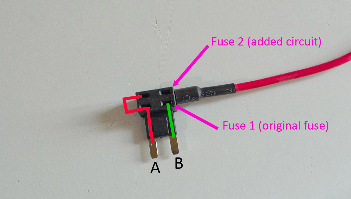
You have to plug terminal A of the add-a-fuse into the hot side (i.e. the add-a-fuse only works properly one way round), here's why:
Once you install fuses in the add-a-fuse, each pair of sockets is connected (the blue lines). Thus, if we apply 12V+ to terminal A, power flows 1) From terminal A, through the lower (fuse 1) fuse, and to terminal B...this completes the original circuit, independent of the added circuit. Power also flows from terminal A to the left-hand socket of the top (fuse 2) fuse, through fuse 2, and out the pigtail wire. This is the proper way, where both circuits are independent and the fuse sizes do not need to be matched. This is illustrated by the pink arrows. |
| |
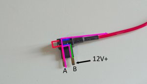 |
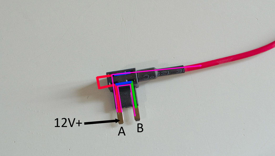
However, if you plug the add-a-fuse in the other way around (the incorrect way), with terminal B being plugged into the hot side of the terminal in the fuse box, you get the following:
In this situation, 12V+ will flow from terminal B, through fuse 1, and out terminal A, completing the original circuit, and misleading you into thinking everything is OK. BUT...because there is no connection between terminal B and the right socket of fuse 2 (the top fuse), 12V+ will only flow out the pigtail wire THROUGH fuse 1 in series. Again, this is shown by the pink arrows. As such, it is quite possible that the combination of loads on fuse 1 will blow the fuse. Also, if you install the add-a-fuse this wrong way around in an open slot in your fuse box, you have to install BOTH fuses in the add-a-fuse even if you are only powering the one new circuit (this is a big clue you have it the wrong way around) |
Bottom line:
If you are installing it into an empty slot, just install the fuse for the boost gauge in the slot furthest from the metal legs or prongs.
If you are installing into a slot with a fuse, take that fuse out and put it into the slot closest to the metal legs or prongs, and put the fuse for the boost gauge into the other slot.
Then you just have to install it in the right orientation (which, when using the middle row of the interior fuse block means with the pigtail wire facing up). |
 |
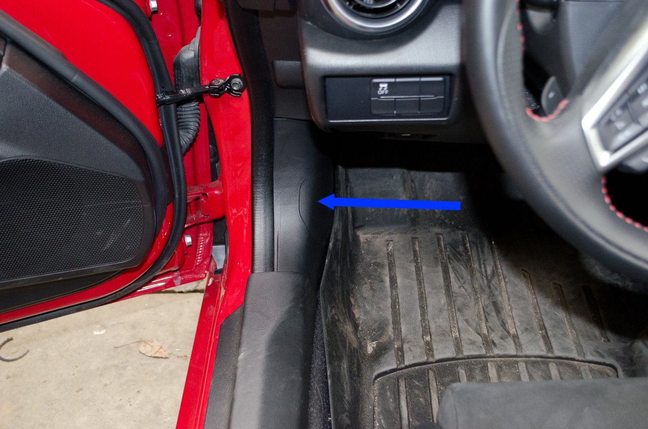
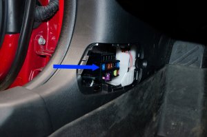
Here is the interior fuse block. |
| |
 |
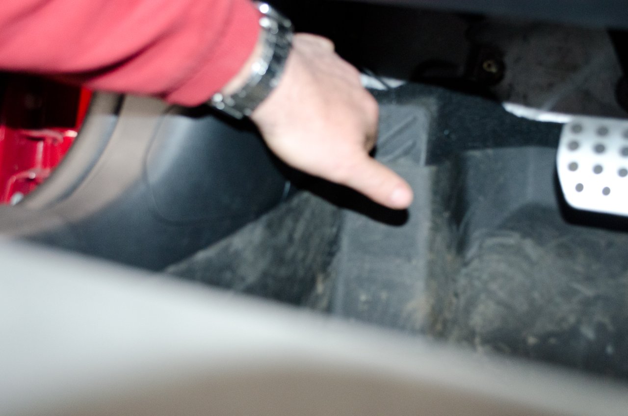
If you reach in from outside the car to the front end of the cover panel, you will feel a small detent for your fingers.
Just pull the cover off by pulling it towards you. |
| |
 |
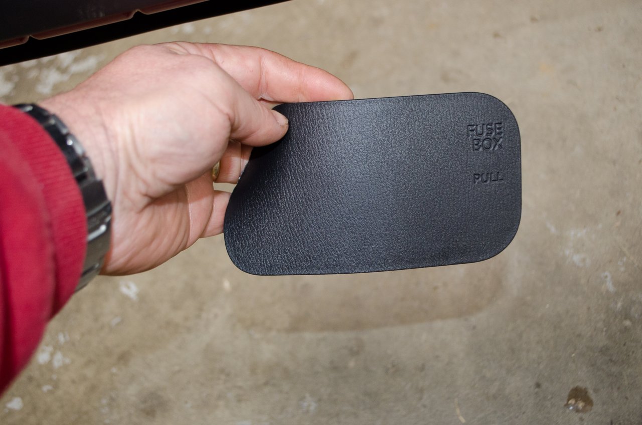
Cover removed. |
| |
 |
This is the middle row which we will be using. |
| |
 |
Here the two fuse taps are installed in the correct orientation in the fuse block.
F6 supplies the 12V+ ignition switched power and will connect to the yellow wire on the Vaitrix power wiring harness.
F10 supplies 12V+ battery power and will connect to the red wire on the Vaitrix power wiring harness. |
| |
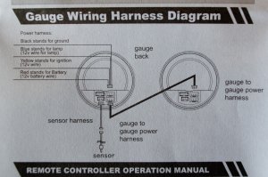 |
This shows the wiring diagram. |
| |
 |
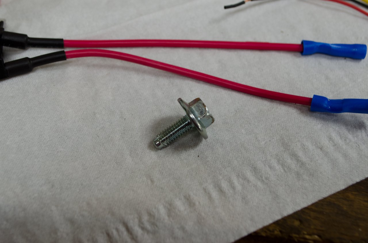
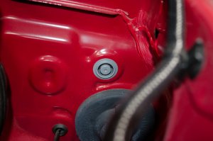
For the required ground connection, I removed the rear-most mounting bolt of the fuse block (pictured at left), crimped a ring terminal on the black Vaitrix wire, slipped the mounting bolt through the ring terminal, and reinstalled the bolt. |
You can crimp or solder the Vaitrix wires to the pigtails. If you crimp, since the Vaitrix wires are so small, it can be helpful to strip a generous amount of insulation and fold the bare wire over on itself a couple of times to form a larger "plug" of bare wire for the crimp connector to crimp on to. |
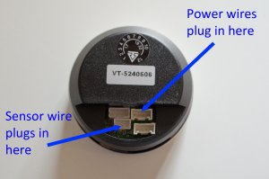 |
At this point, you will now have the sensor wire and the power wires in the cabin ready to be routed and plugged into the gauge as shown here.
Routing will of course depend on where you choose to mount the gauge. Keep the wires neat, tucked in, and secured with zip ties so they don't flop about or chafe on anything. |
| |
|
When you are all finished, don't forget to reconnect the battery. |
| |
 |
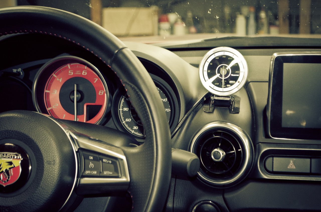
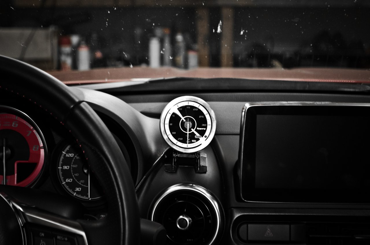
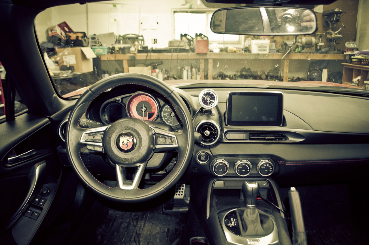
I routed the wires under the dash and then out by the right side of the steering column, mounting the gauge just above the vent, as shown.
The supplied mounting bracket is fairly straightforward and can be stuck in position with the supplied 3M double-sided tape.
The "segmented" nature of the base of the bracket means it conforms well to curves, as was required for this surface. |
| |
 |
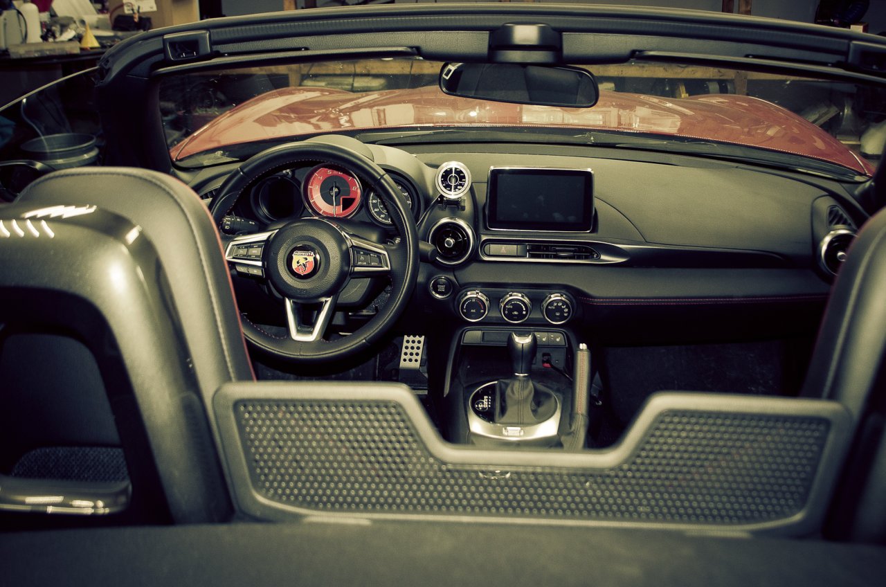
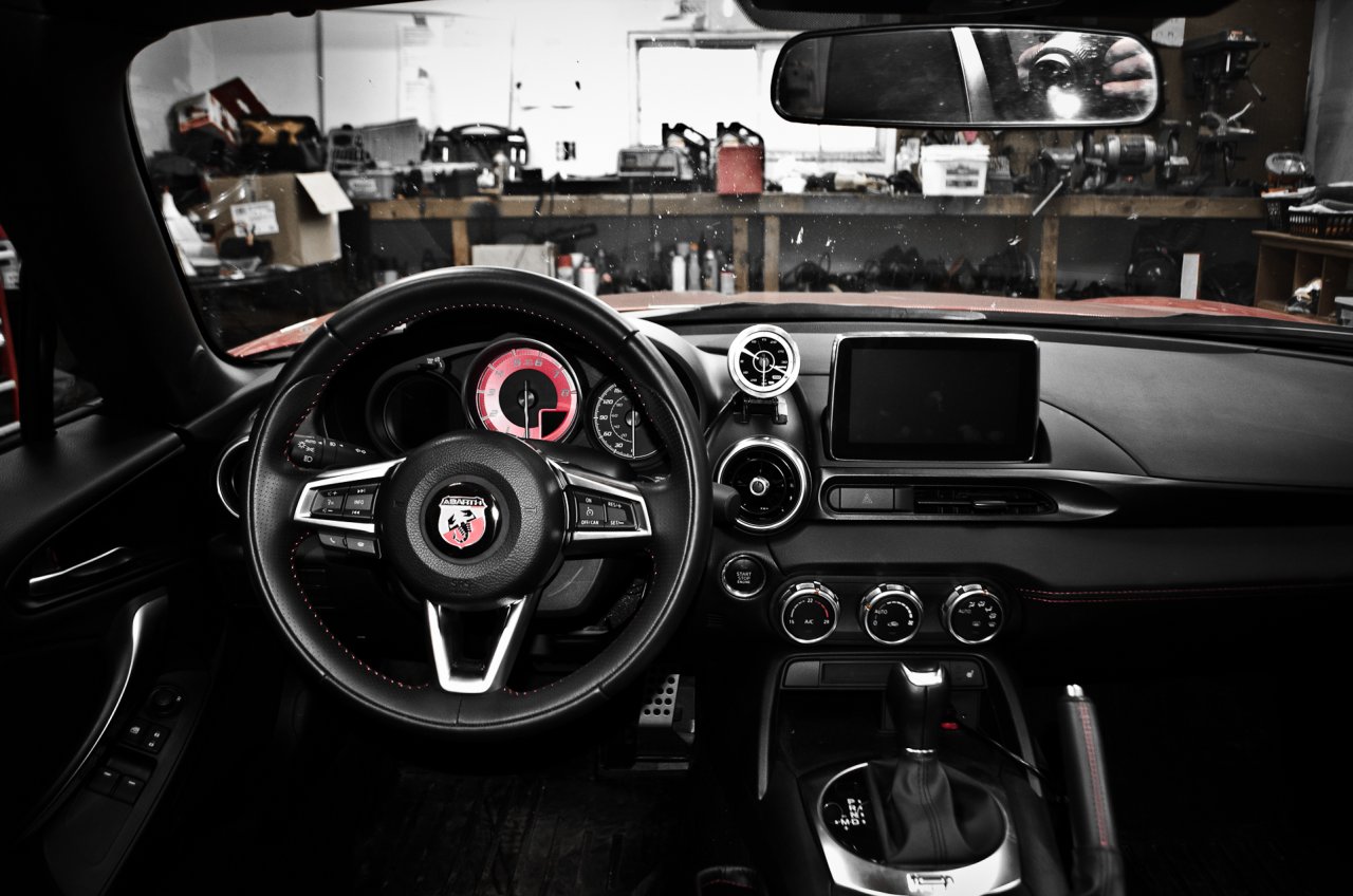
However, in my opinion, the overall effect is somewhat cheap and cheesy. In no way does it look factory - in fact I feel it very much screams "aftermarket stuck on".
And that's a real shame as it cheapens the whole install in my opinion.
I am very much on the hunt for a better mounting option - one more appropriate for the car and the gauge itself - which is a handsome piece. |
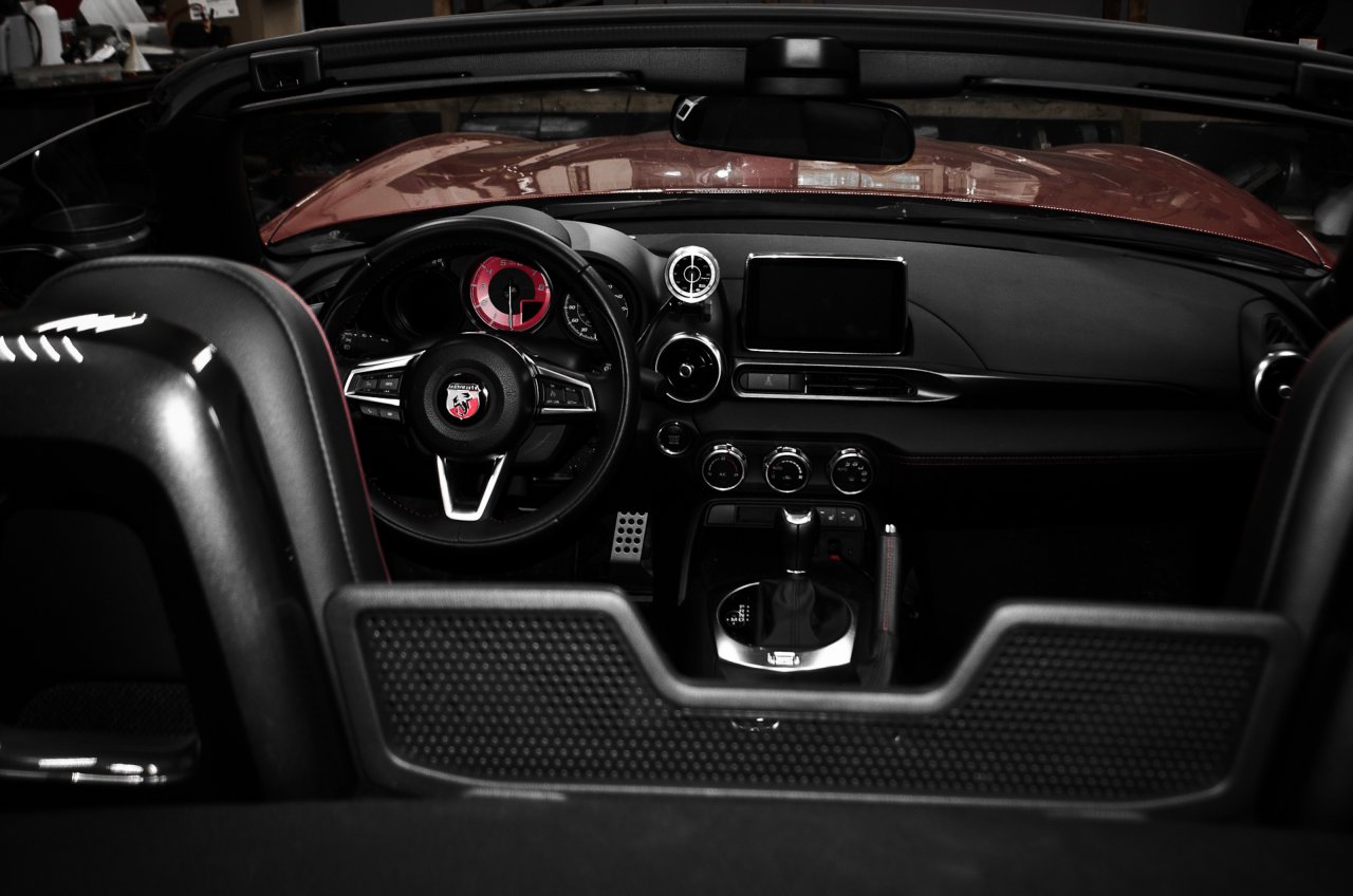
In the meantime, however, here are a few pics of the installed gauge:
The instructions supplied for programming the gauge are pretty awful.
To adjust the alarm for overboost (mine was factory set to 15 psi and so went off constantly). |
 |
Begin by removing the little cardboard protector keeping the battery from making contact in the remote. Just pull it out. |
| |
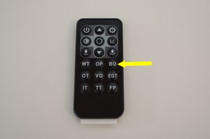 |
Without touching brake or clutch, press start button once to turn on ACC power.
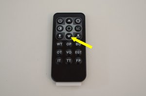
Aim remote at gauge and press button marked BO – needle will flash. |
| |
 |
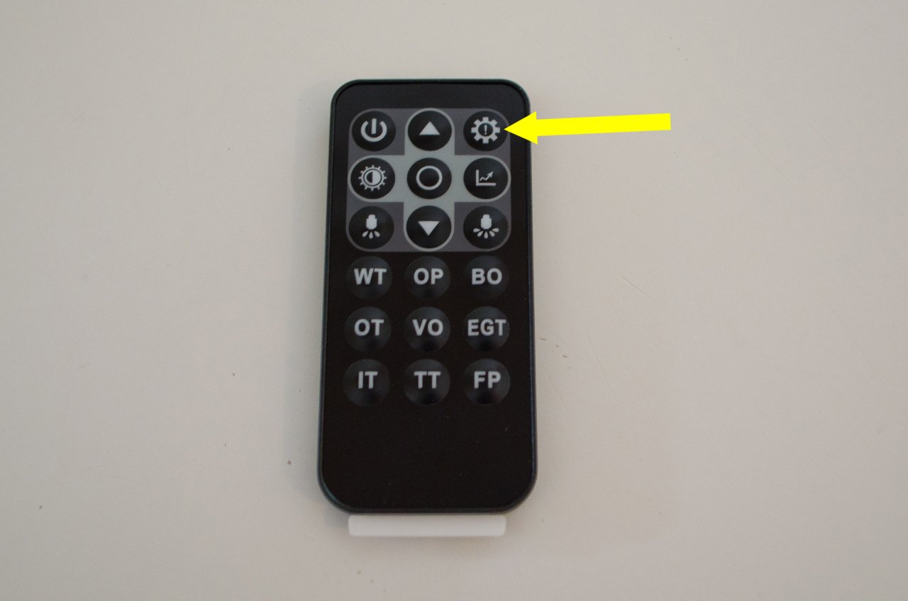
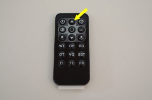
Press the upper right button, marked with a ! – needle will move to currently programmed alarm limit (in my case 15 psi). |
| |
 |
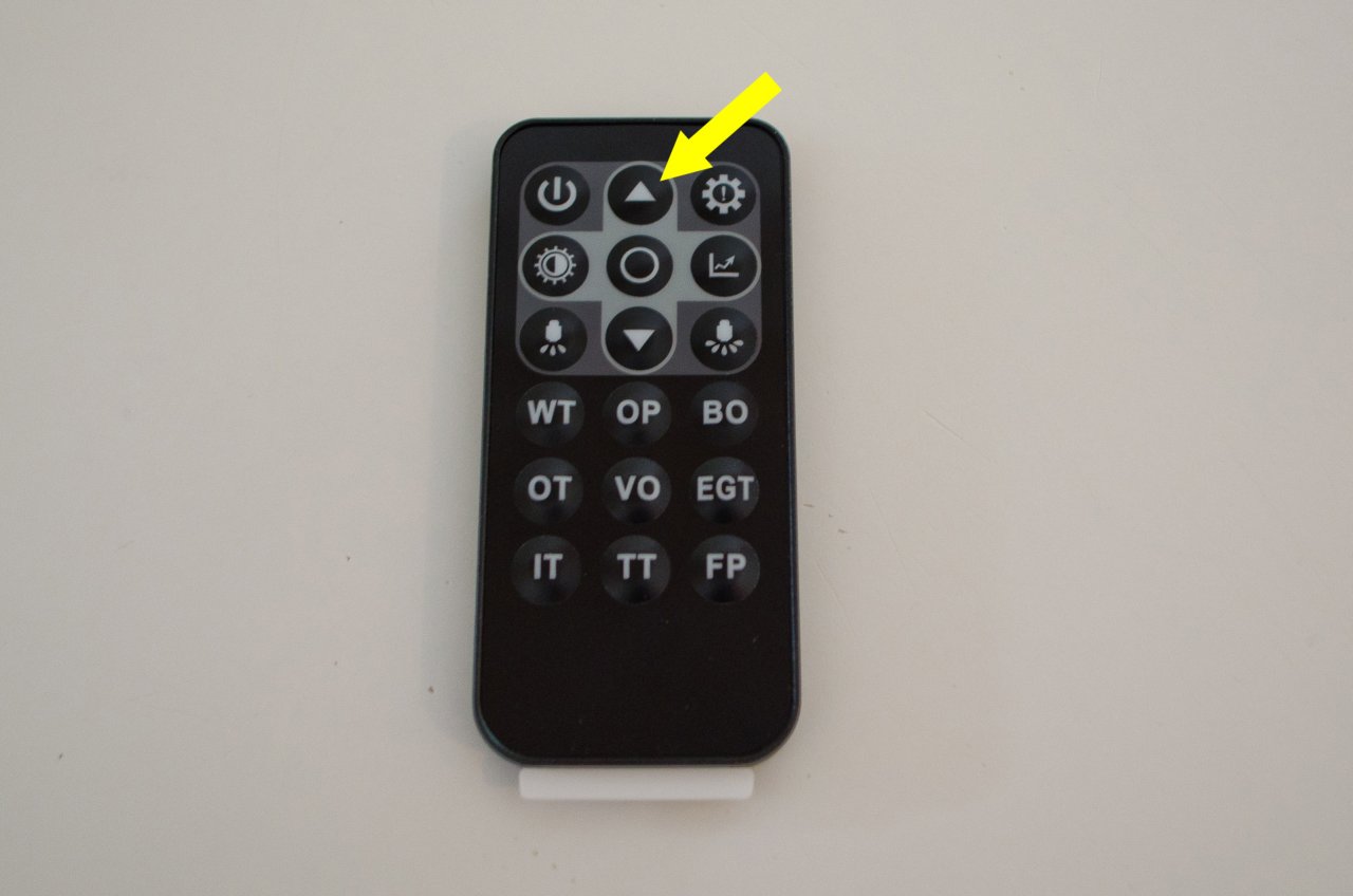
Press the up-arrow button to increase the limit – the needle will move accordingly. Multiple presses are required. I set mine to 25 psi. |
| |
 |
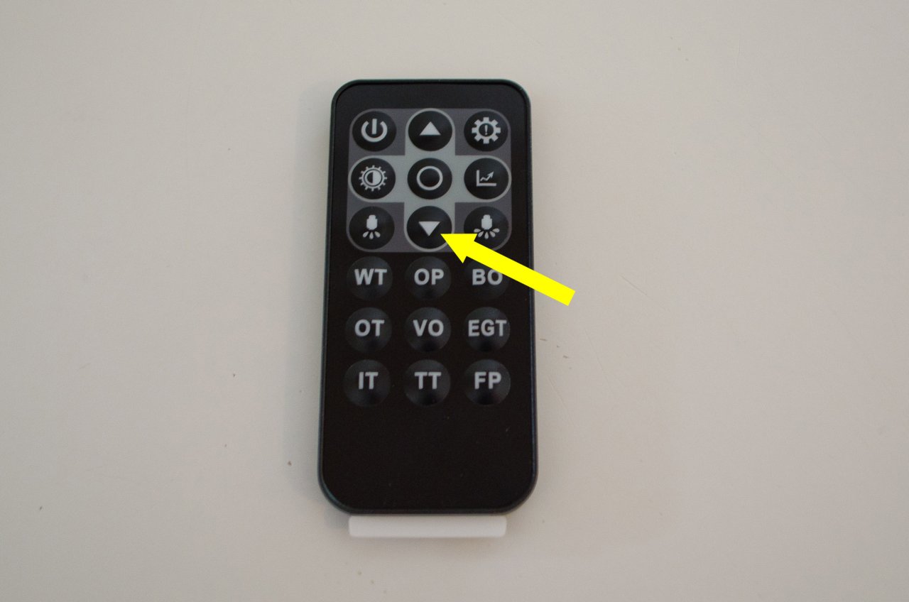
If you go too far – press the down arrow to decrease the limit – the needle will move down accordingly. |
| |
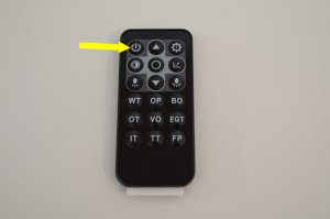 |
When you are happy with the setting, as indicated by the needle, press the power button (top left) to exit the programming mode.
Press the start button twice to turn off the car.
Note: If you ever disconnect the battery, this setting will be lost and you will have to repeat the procedure. |