 |
EuroCompulsion V4 Intake
Title By Bill "BillaVista" Ansell |
IntroductionInstallation of the EuroCompulsion V4 Intake System on my 2017 FIAT 124 Spider Abarth. Note this article will present a slightly different approach / order of steps than is seen in the official instructions or in other online tutorials. The reason is simple - after decades of experience (screwing even simple things up) I have a knack for figuring out what might confuse or confound a beginner that might not have been obvious to an expert. Put another way - I have a god-given talent that if there's a way to screw up...I will screw it up. So, after much thought, what follows is a series of steps that I believe is most likely to guarantee satisfactory results on your first try! |
 |
 |
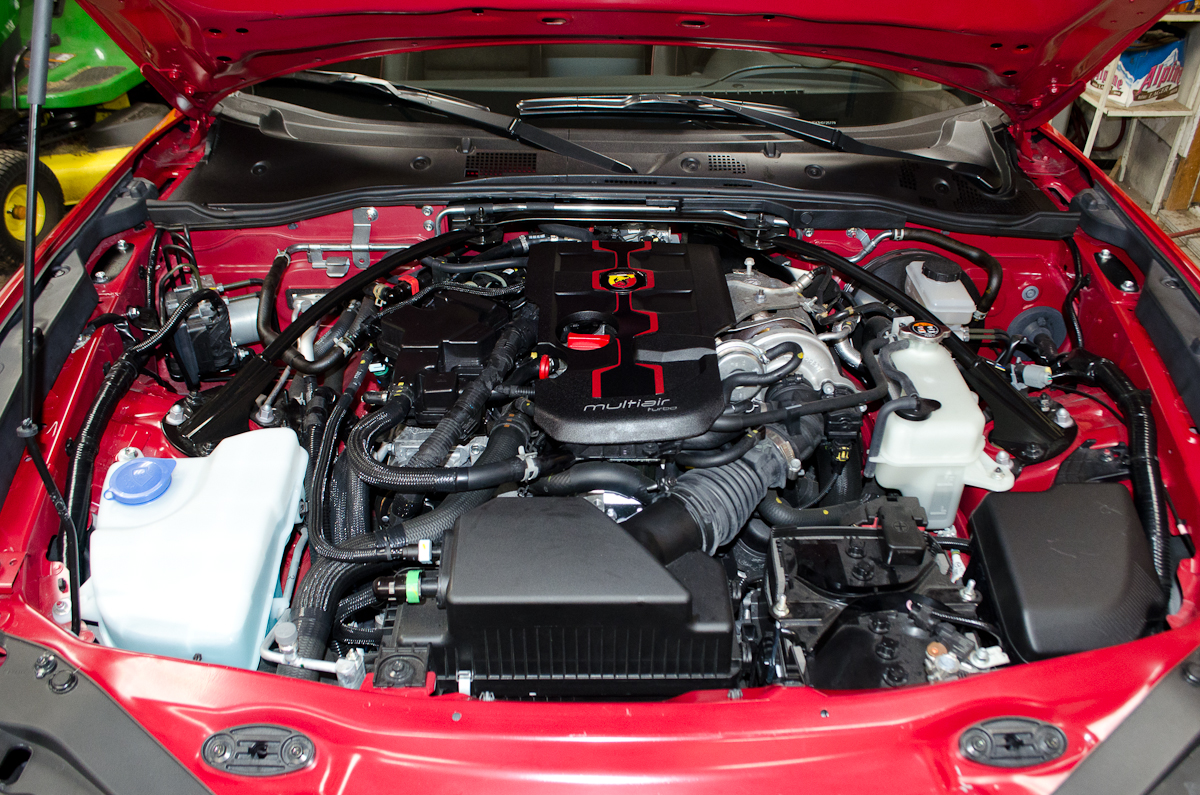
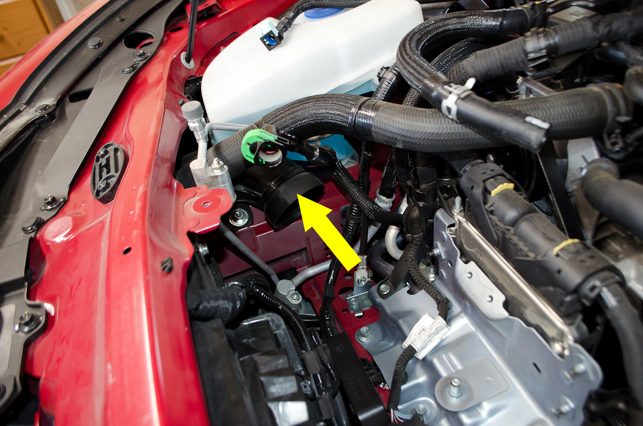
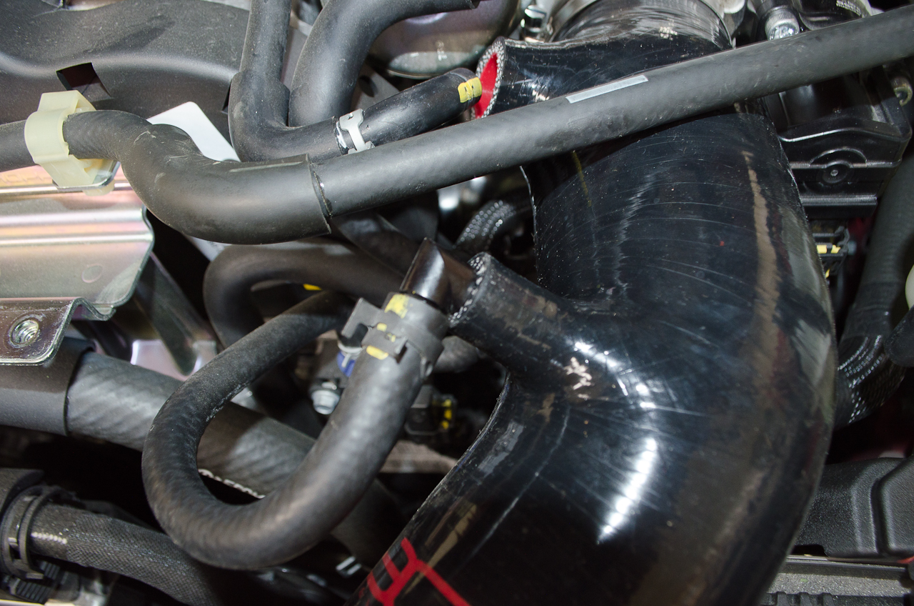
A detailed step-by-step look at how to take this, to go from... |
 |
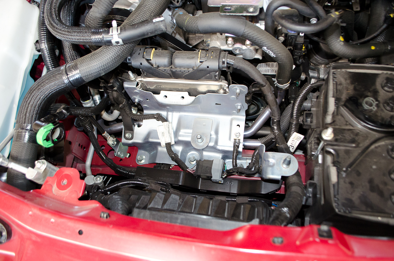
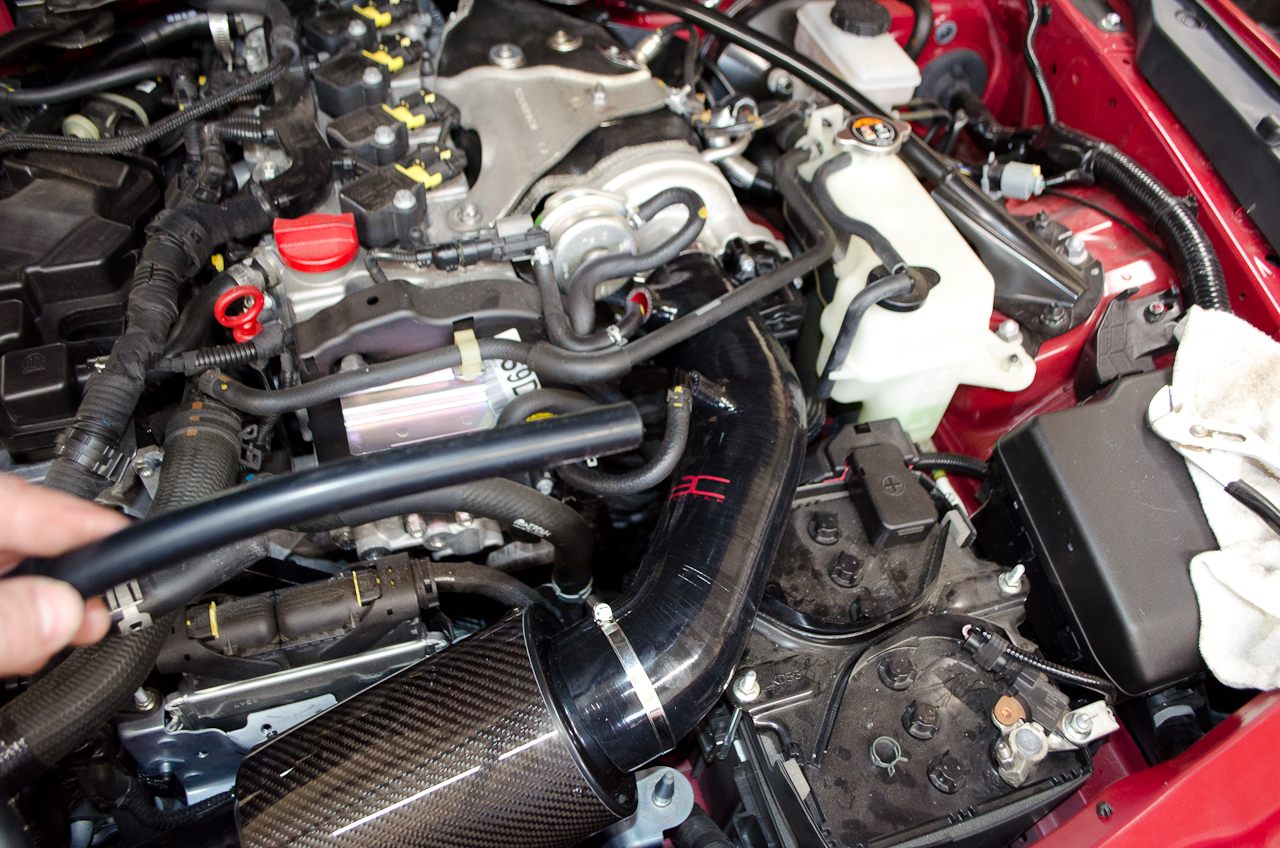
...this... |
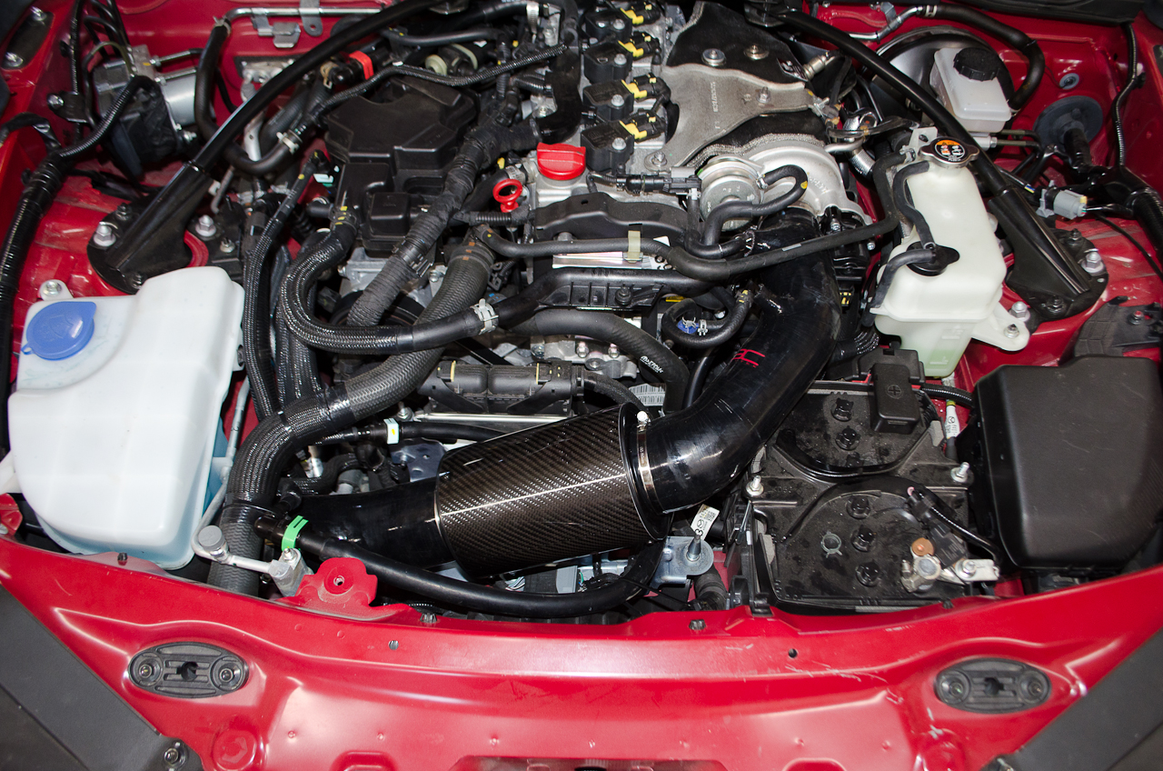 |
...to this! |
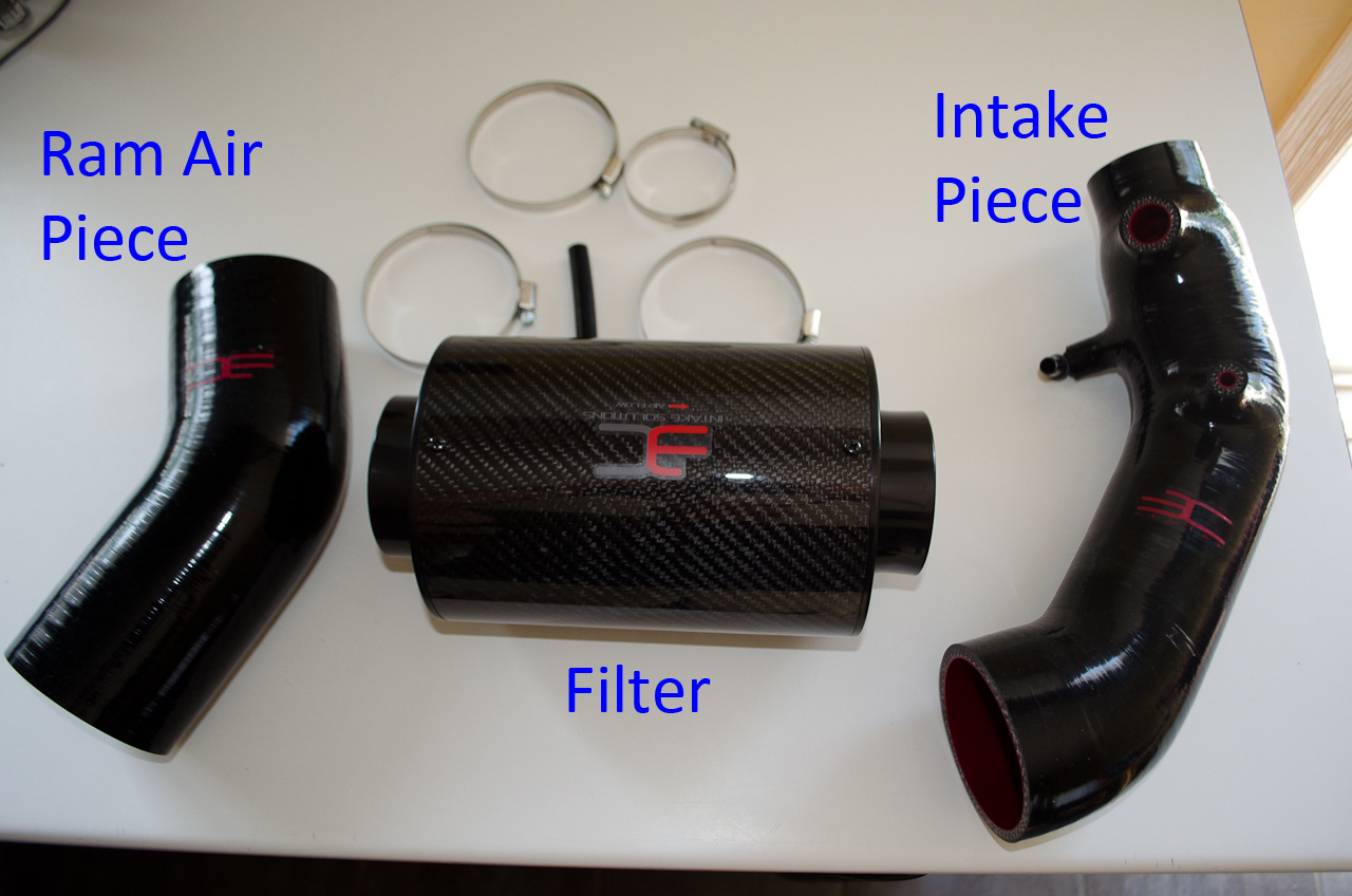 |
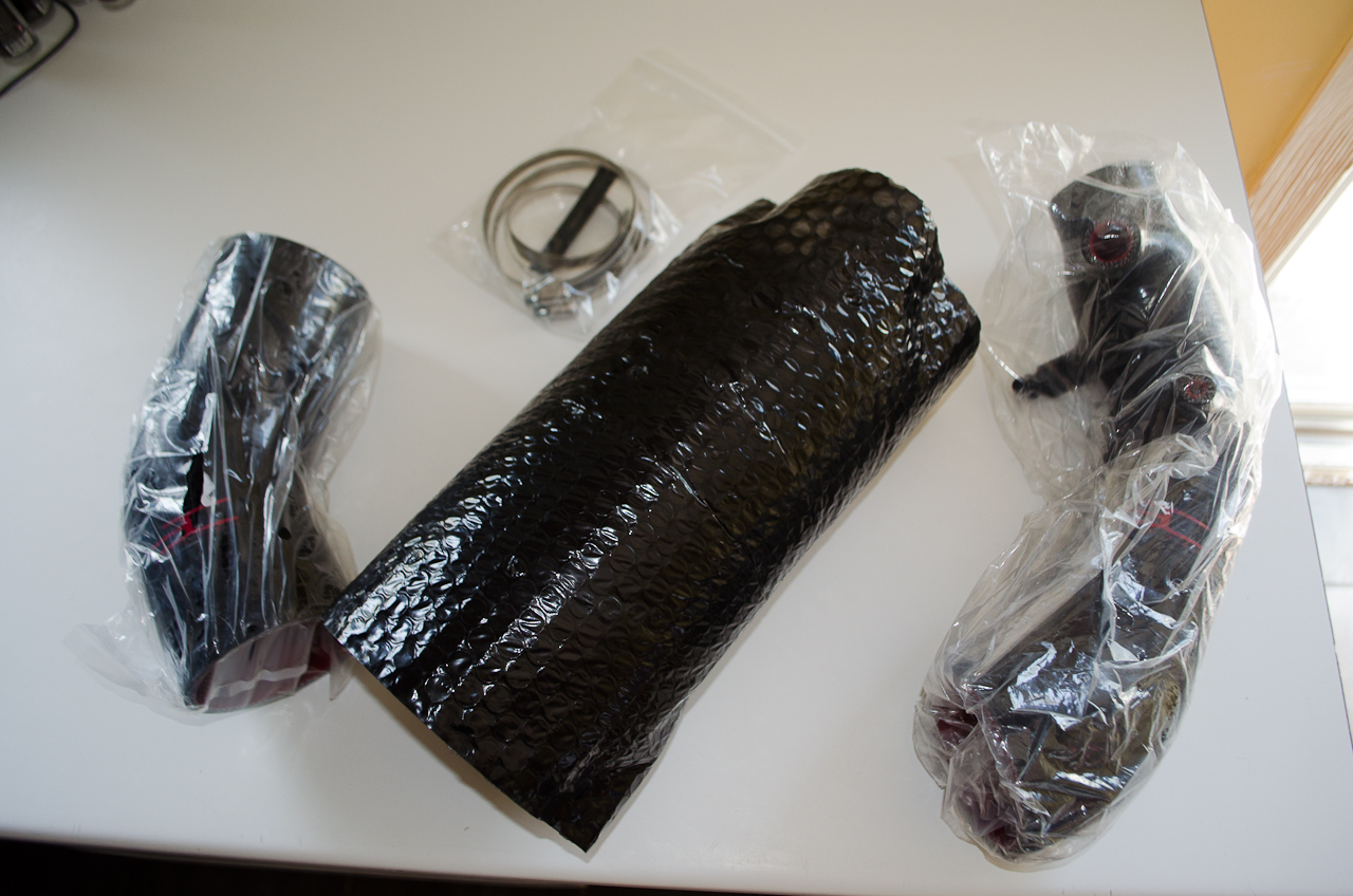
Let's get acquainted with the parts in the kit first. The main components are the ram air piece, the cannister filter, and the intake piece. The order of installation goes: Front Bumper -> RAM air intake -> Ram Air Piece -> Filter -> Intake Piece -> Turbo. The bold-text indicates pieces from the EuroCompulsion (EC) kit, the rest are factory stock. |
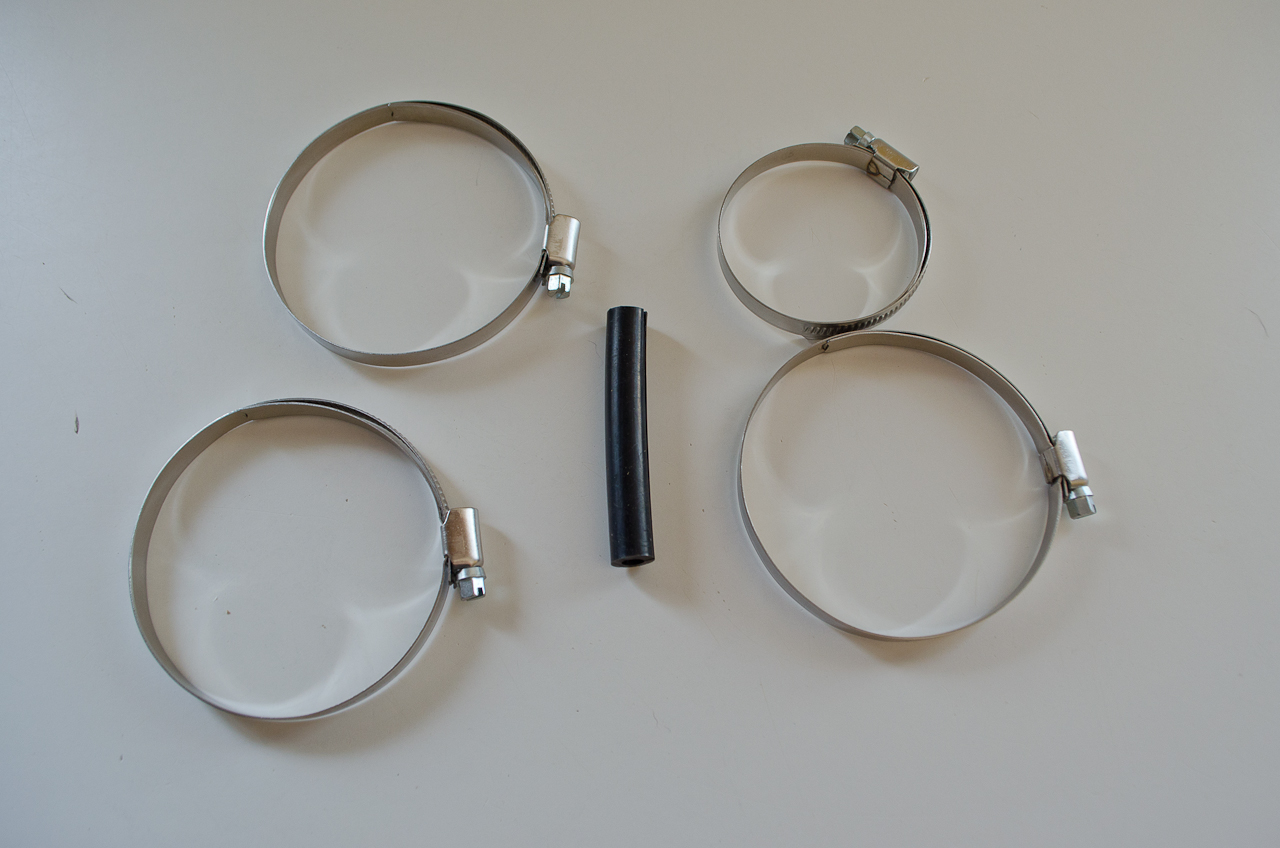 |
There are also three large hose clamps, one smaller hose clamp, and a small piece of split rubber hose to act as a wear guard. |
 |
Finally there is a section of vacuum tubing to make the necessary connection to the evap hoses in the car. |
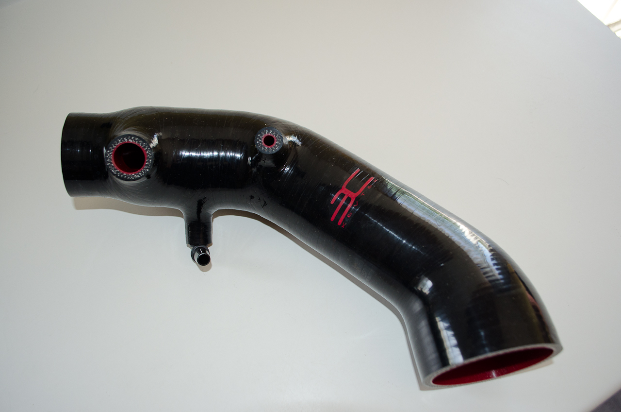 |
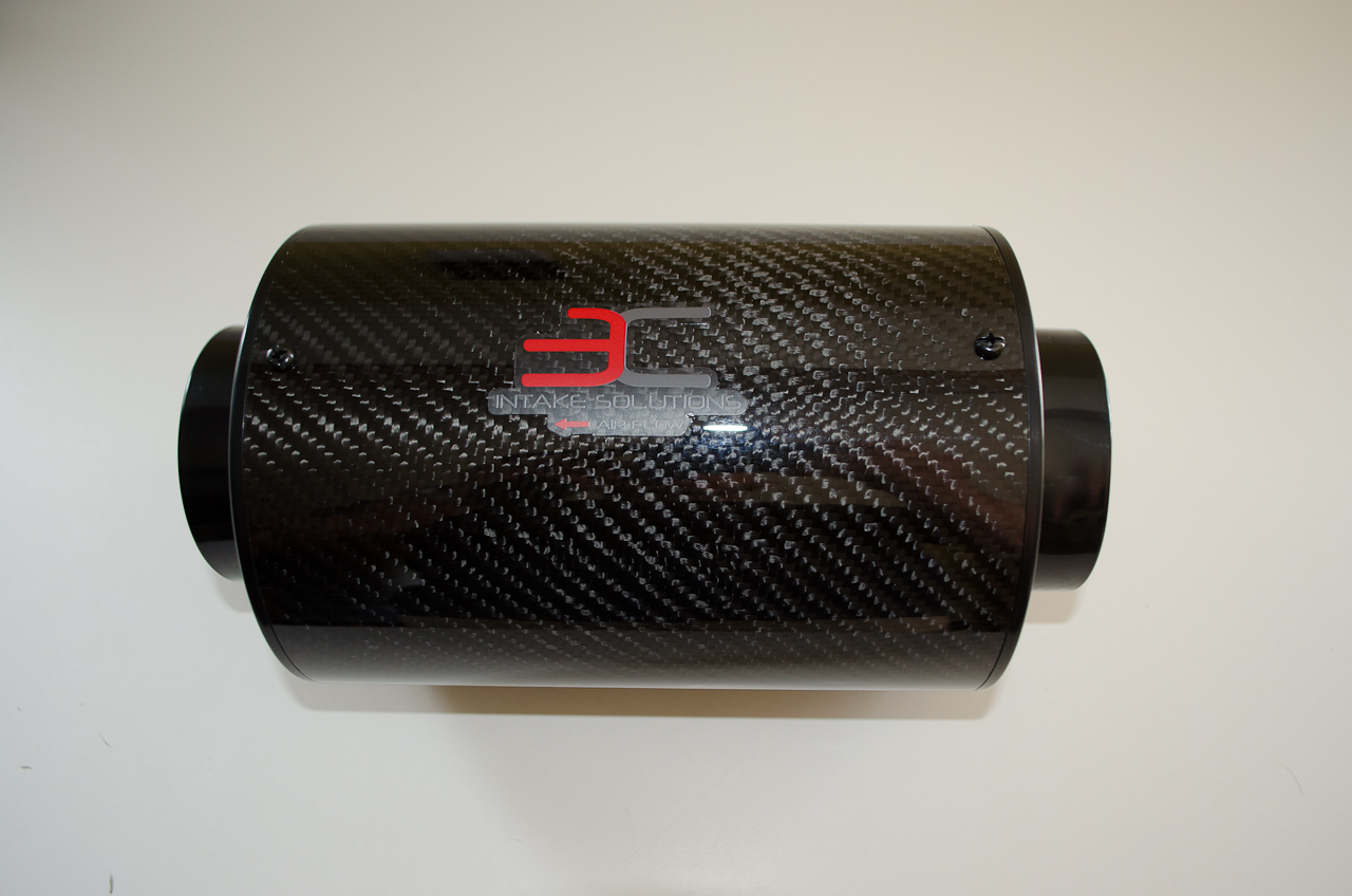
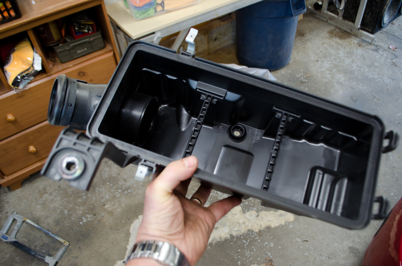
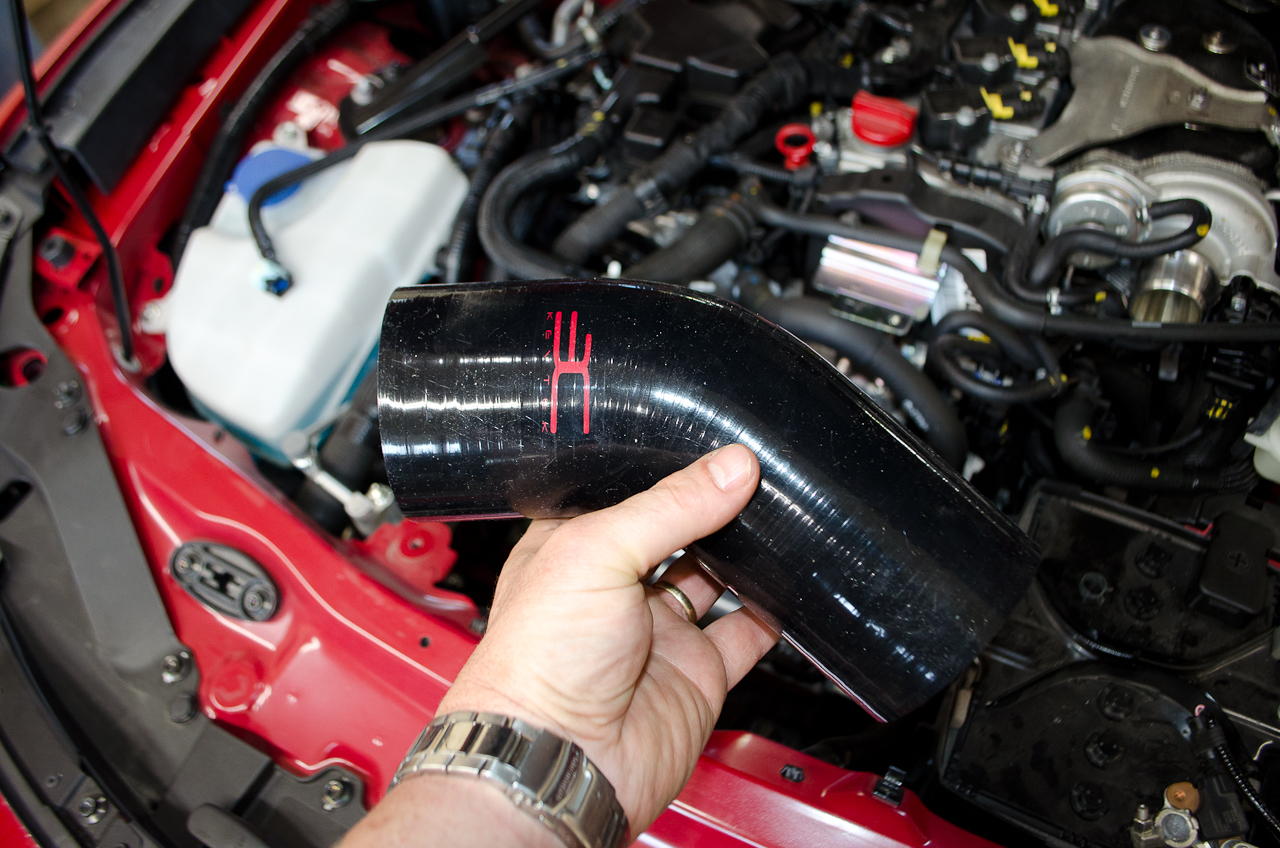
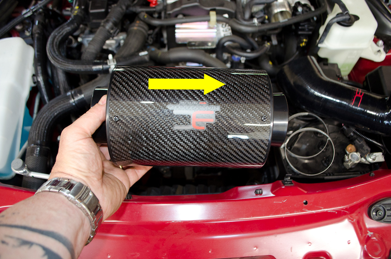
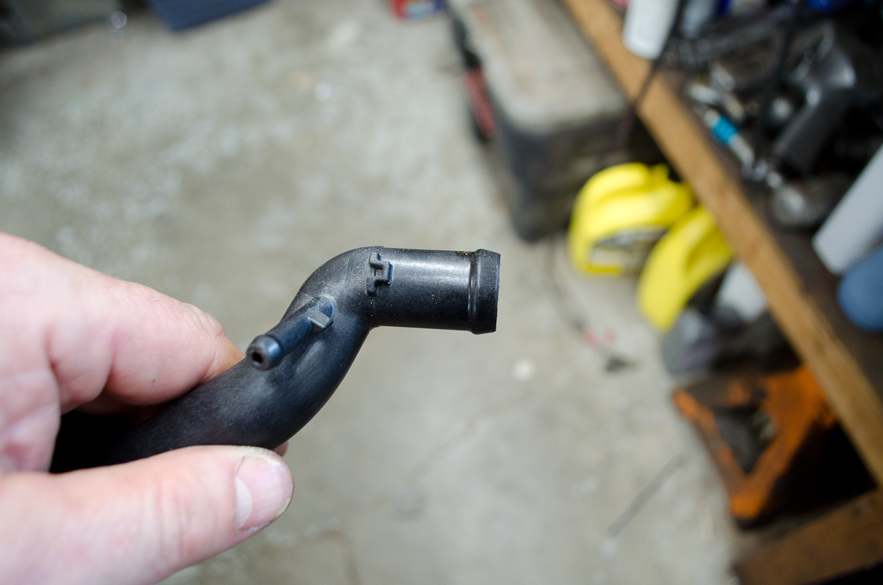
The intake piece is really the business end, as it contains two ports (one large, one small) as well as a nipple, to which you must make the necessary connections. Don't worry, it's not as complicated as it might seem. |
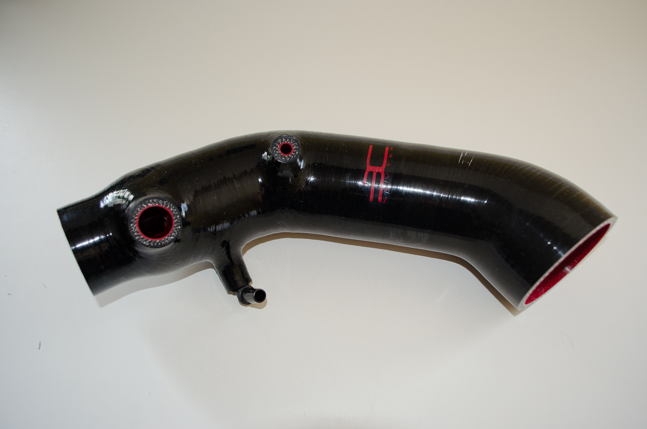 |
Intake piece. |
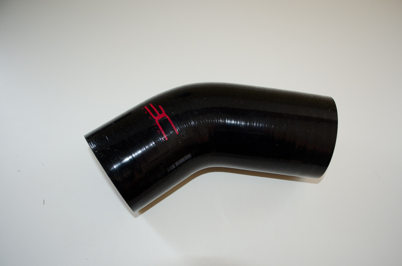 |
The RAM air piece is a short section of silicone intake hose that goes between the car's RAM air intake and the EC filter. |
 |
RAM air piece. |
|
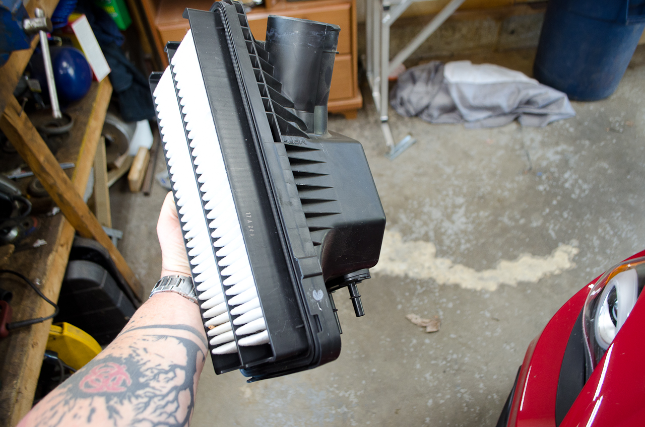
The filter is a washable, re-useable cannister filter. |
 |
Pay close attention to the sticker which indicates the direction of airflow (which is left - to - right as you are standing in front of the car looking at the engine). That little red arrow indicates the direction of airflow...the arrowhead should point towards the turbo. Yes, that means that the EC logo portion of the sticker will be upside down when the filter is installed correctly. |
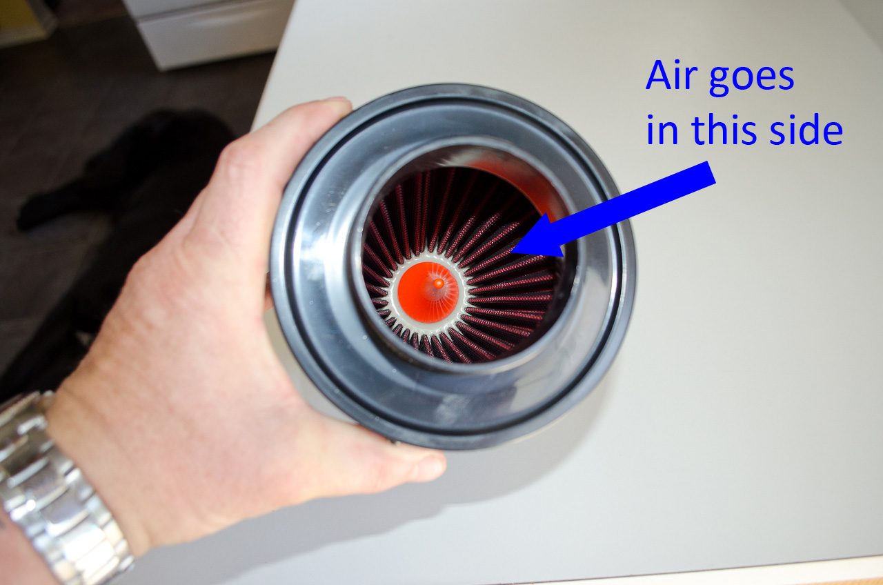 |
In case you should ever get confused, you can tell which end is which by looking in the ends of the filter. One side has an orange conical protrusion (like a small traffic cone) in there...this is the air inlet - the side air goes in BEFORE being filtered. |
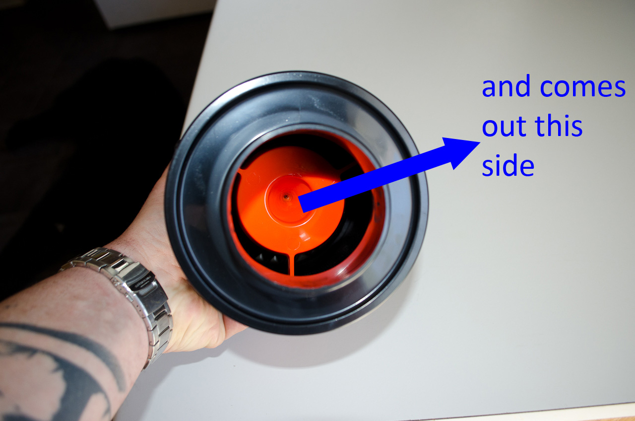 |
The other end has an orange disc - this is the end the filtered air comes out on its way to the turbo. |
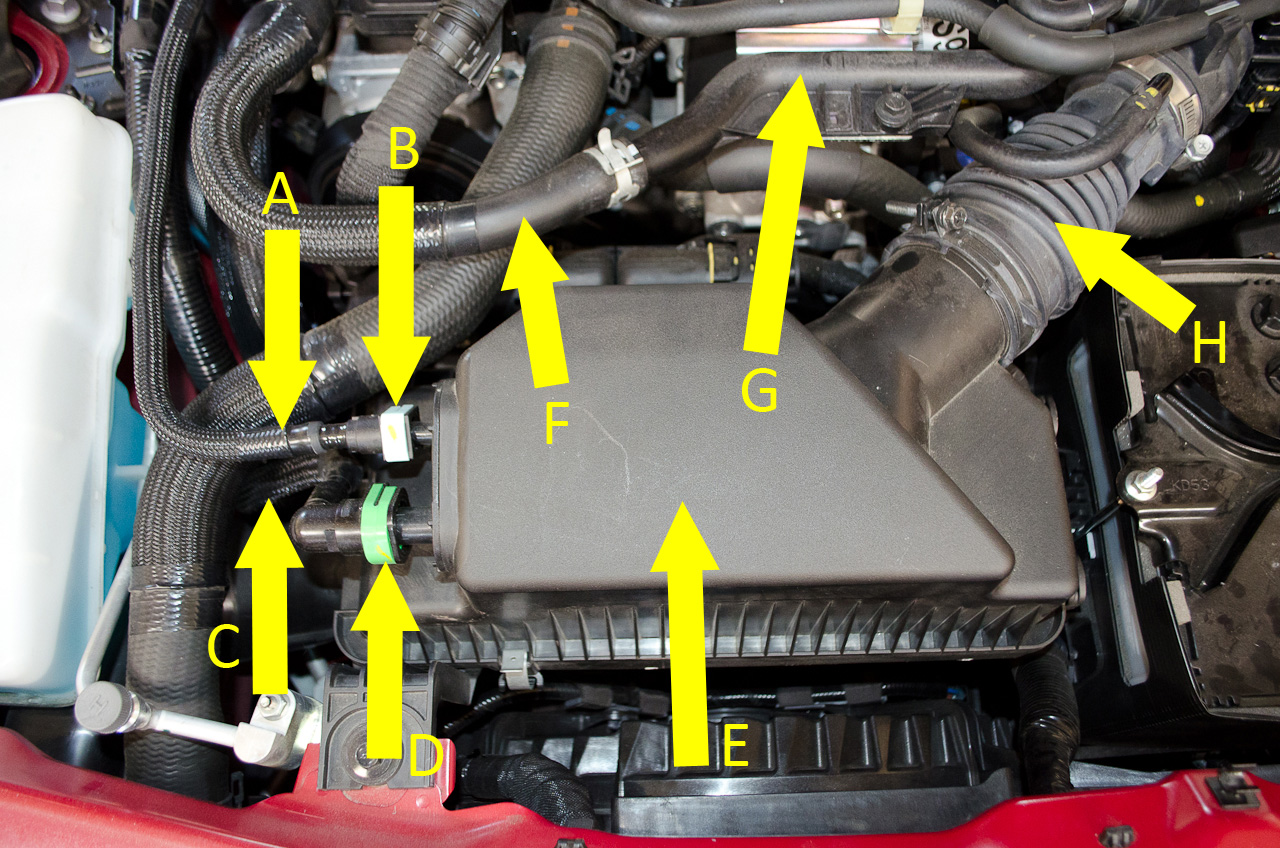 |
Now lets familiarize ourselves with the names of the stock parts we are going to be interacting with during this installation. A. Blue Vapour Recovery Hose
|
 |
A. Oil Vapour Pressure Sensor Pipe B. Waste Gate Solenoid Valve Recirculation Pipe C. Turbocharger Air Inlet Pipe D. Cooling System Pipe |
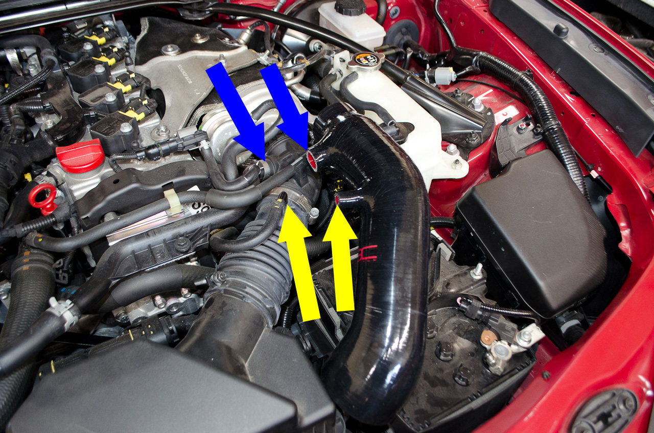 |
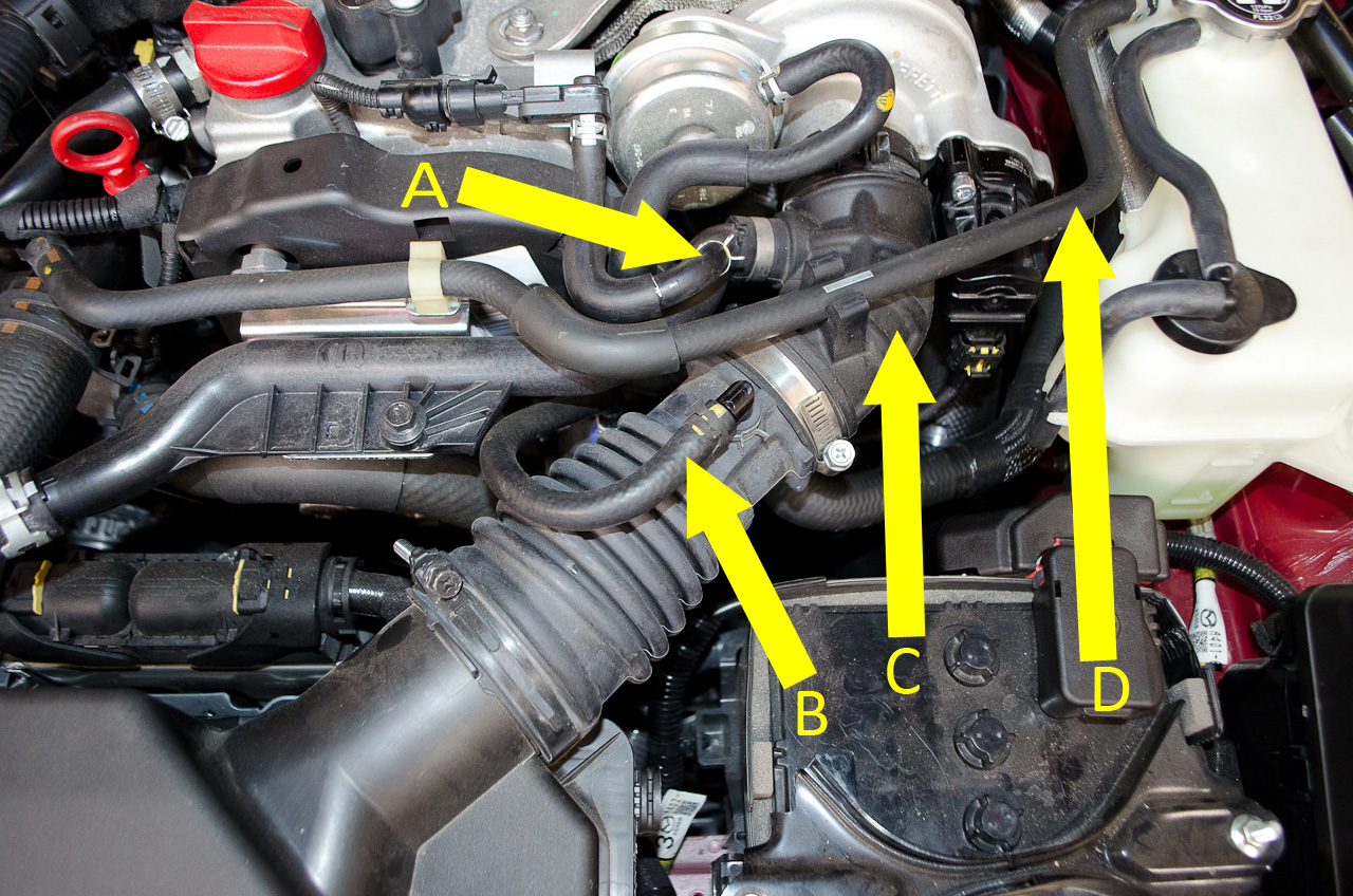
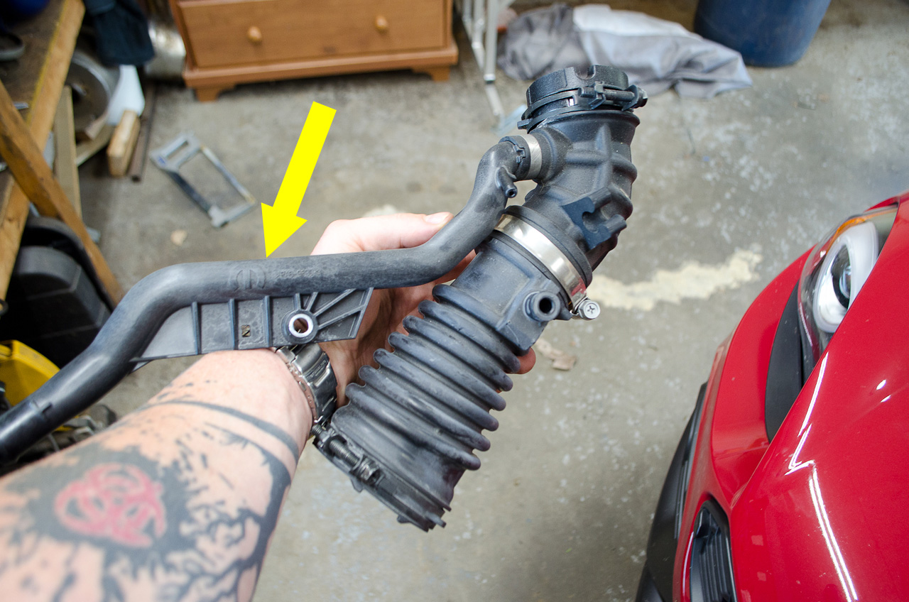
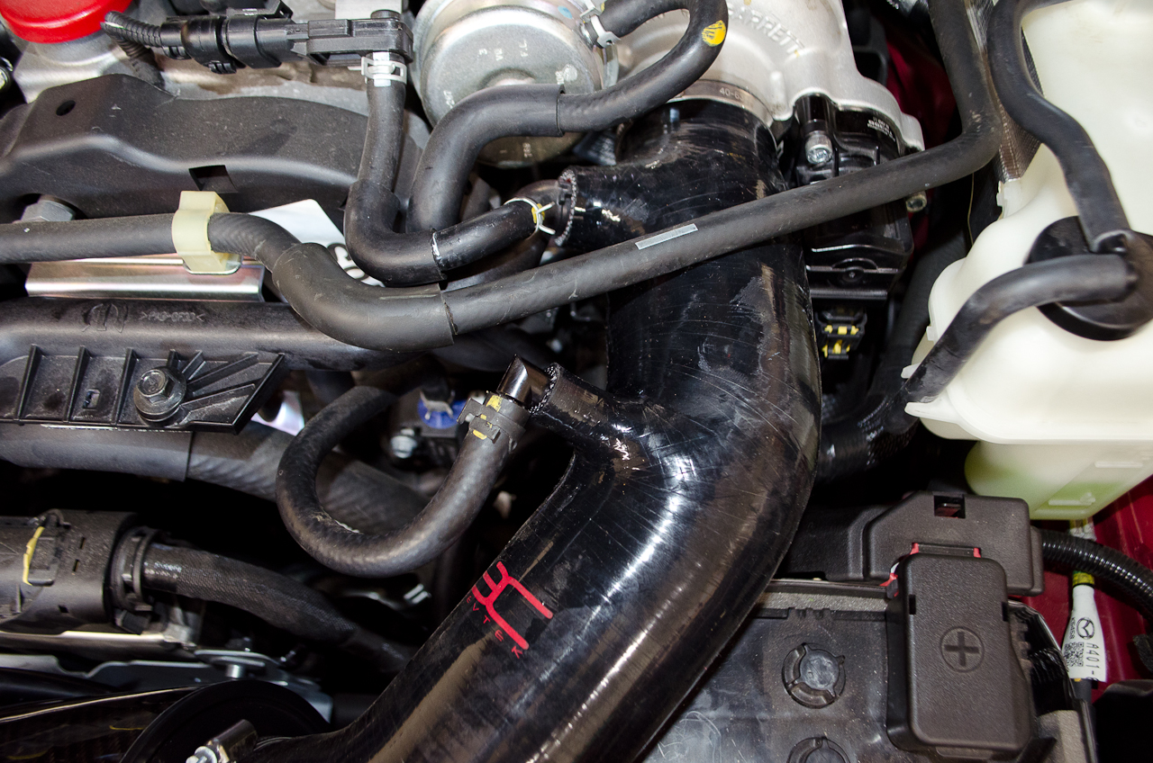
Remember how I said the intake piece was the business end? Before I started ripping parts out, I laid it alongside the factory system to visualize how things would go. The arrows indicate a couple of the connections that will be transferred, just so you get the idea. Don't worry, we will go over each one individually later. |
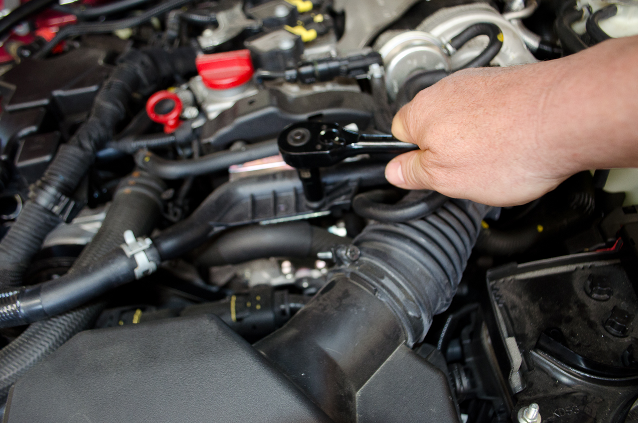 |
Begin by removing the bolt that secures the Rigid Oil Vapour Pipe. It takes a 10mm socket. |
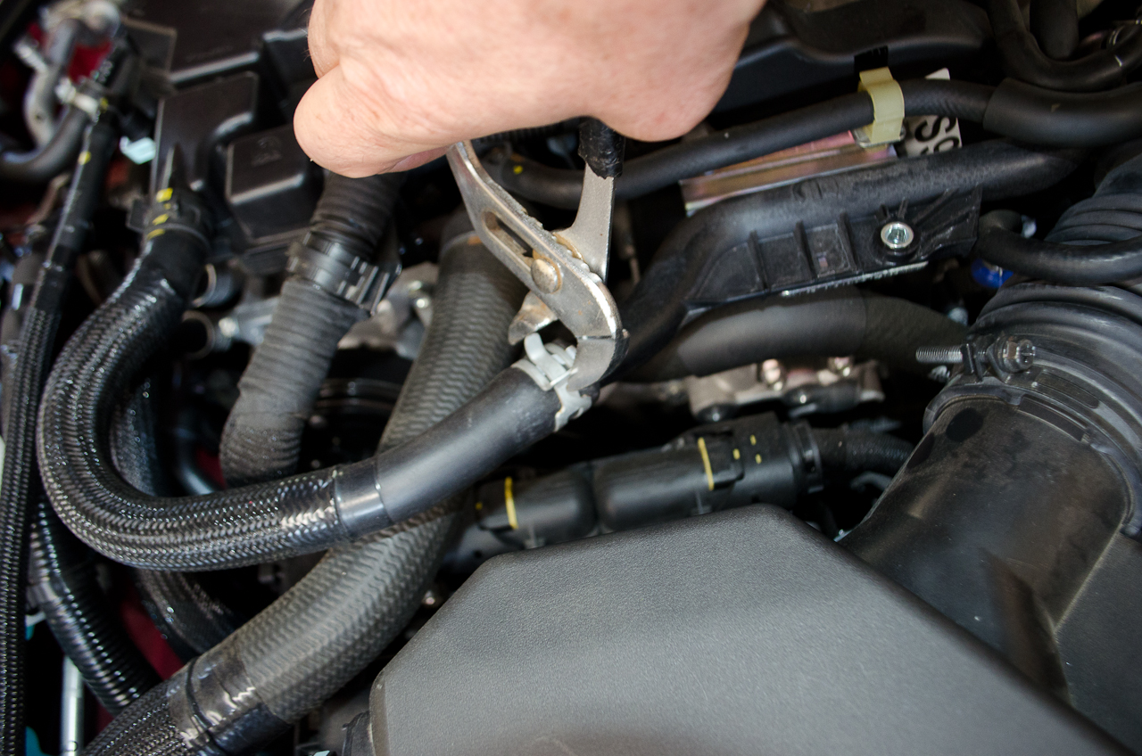 |
Using pliers, loosen the clamp holding the Oil Vapour Pipe to the Rigid Oil Vapour Pipe... |
 |
...and disconnect the Oil Vapour Pipe |
| . | |
 |
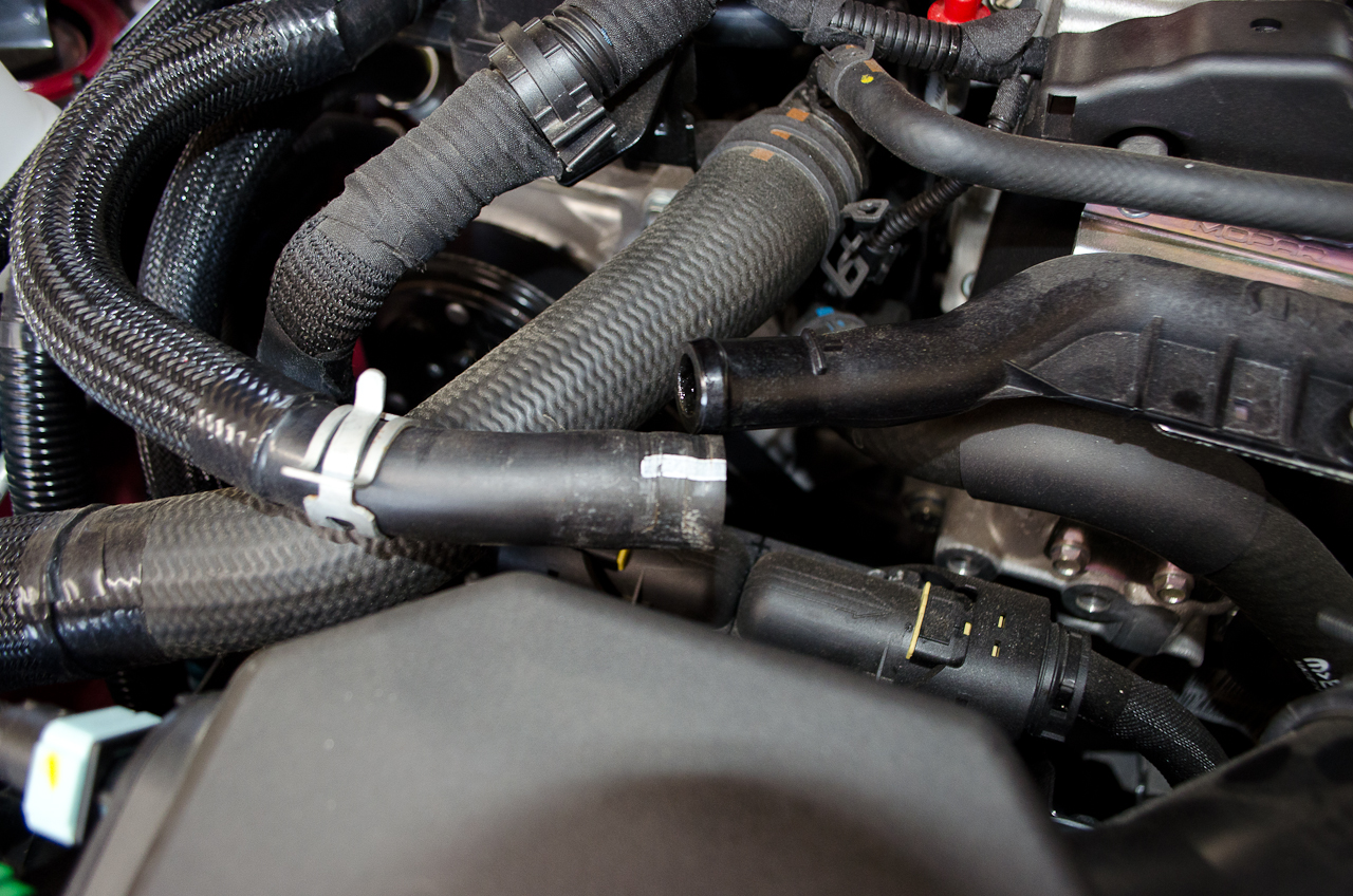
Using pliers, loosen the clamp holding the Waste Gate Solenoid Valve Recirculation Pipe to the port in the Sleeve from the Filter to Turbo Air Inlet Pipe... |
 |
...and remove the Waste Gate Solenoid Valve Recirculation Pipe. |
 |
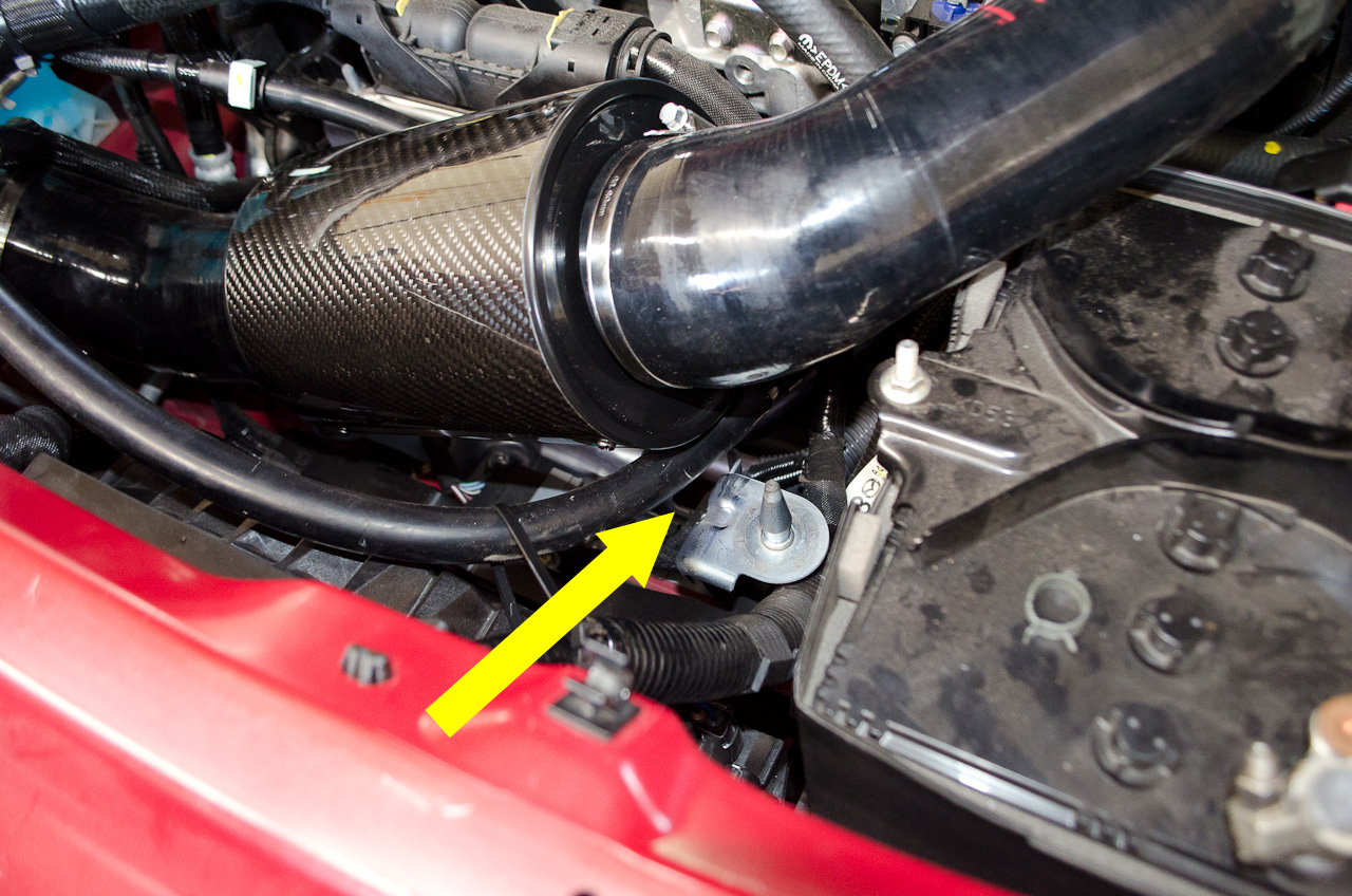
Disconnect the Cooling System Pipe from its bracket on the Turbocharger Air Inlet Pipe. |
 |
Use pliers to remove the clamp holding the Oil Vapour Pressure Sensor Pipe to the nipple on the Rigid Oil Vapour Pipe... |
 |
...and disconnect the hose. |
 |
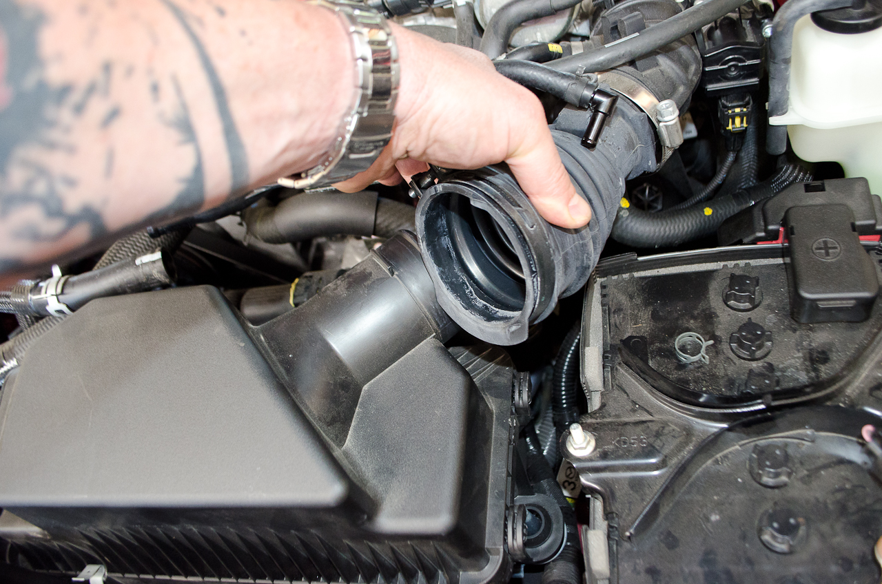
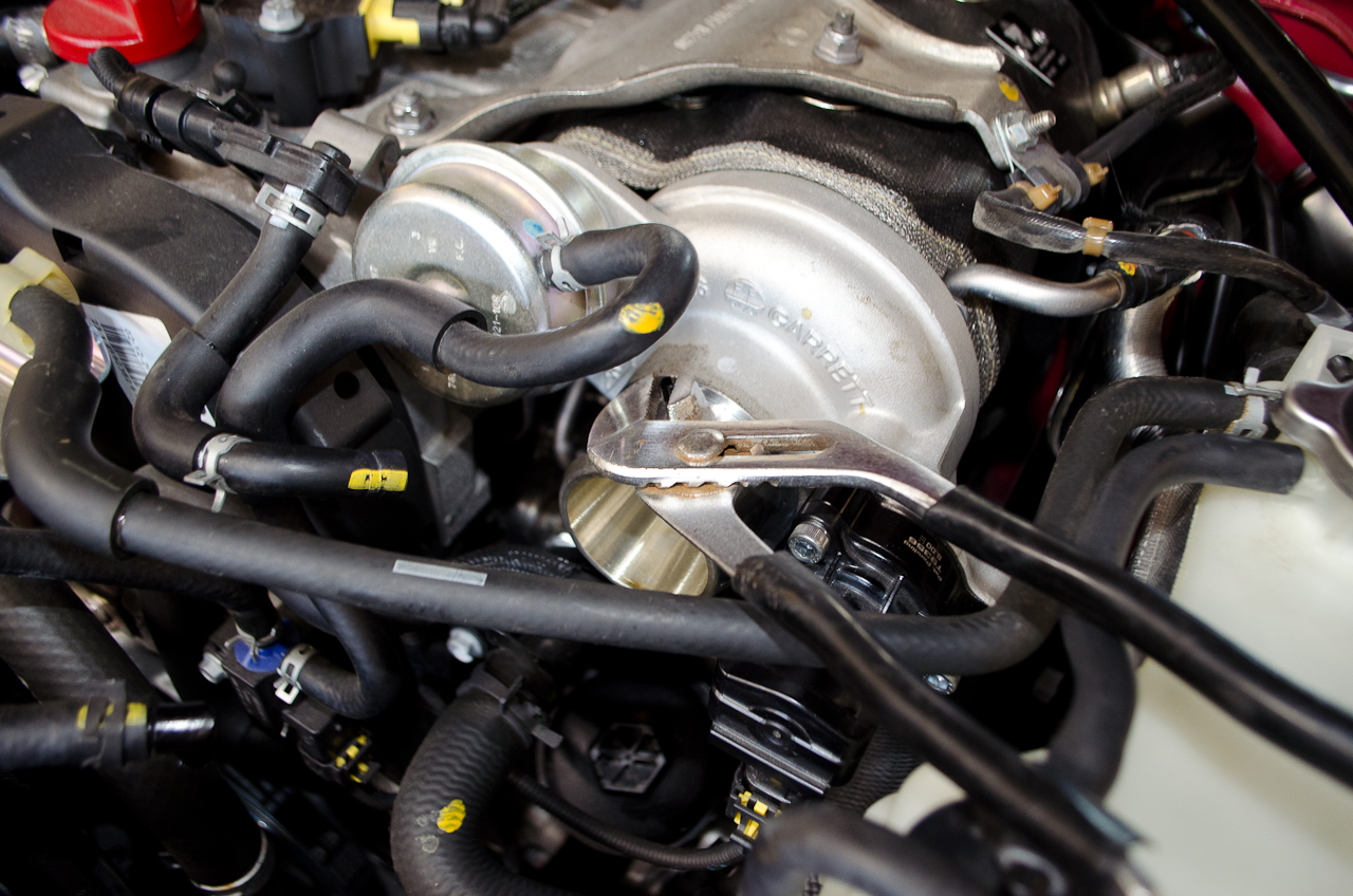
Using a 10mm socket, loosen the clamp holding the Turbocharger Air Inlet Pipe to the turbo inlet. |
 |
Also loosen the clamp between the Sleeve and the Turbo Air Inlet Pipe... |
 |
...and the one between the Airbox and the sleeve. |
 |
Pull the sleeve off the airbox... |
 |
...and the Turbo Air Inlet Pipe off the turbo. |
 |
The assembly will come out with the Rigid Oil Vapour Pipe attached, This is intentional, as it is easier to manipulate out of the car. Set this part aside, we will return to it later. |
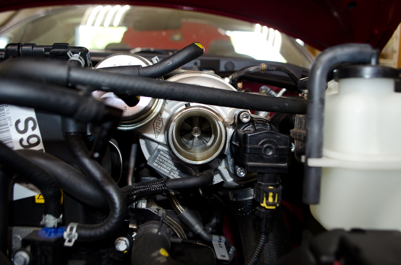 |
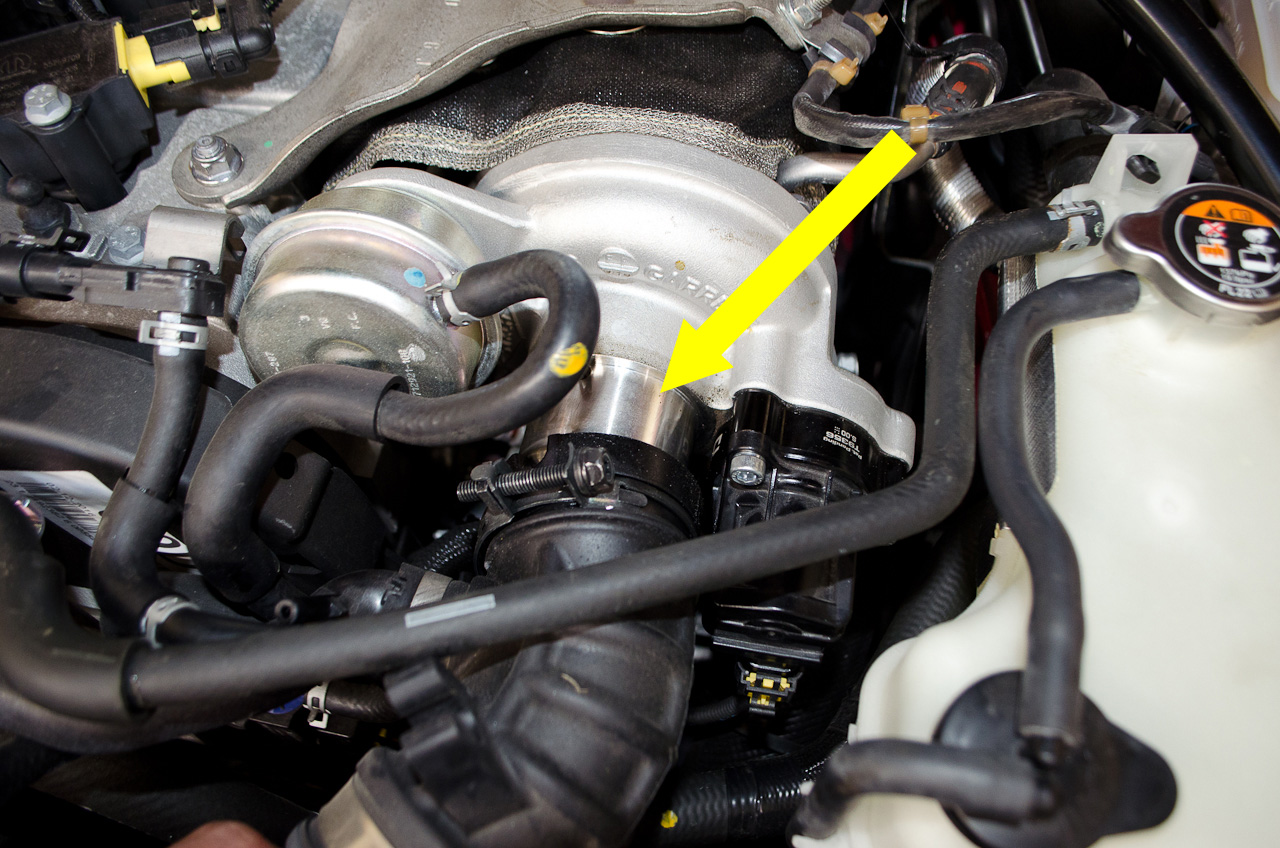
Obligatory look into the turbo while we have stuff removed! |
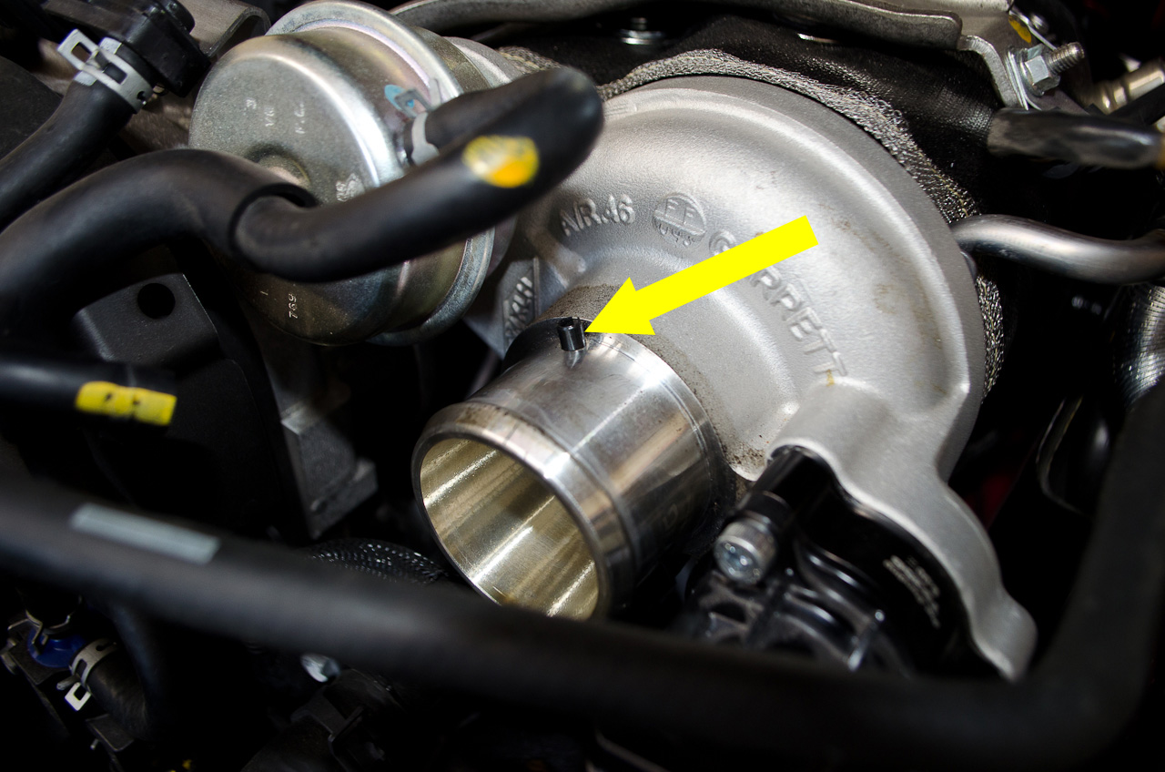 |
You will notice a factory alignment dowel installed in the turbo inlet. This serves no purpose outside factory assembly and can be easily removed. |
 |
Grasp with pliers and pull out with a slight twisting motion. |
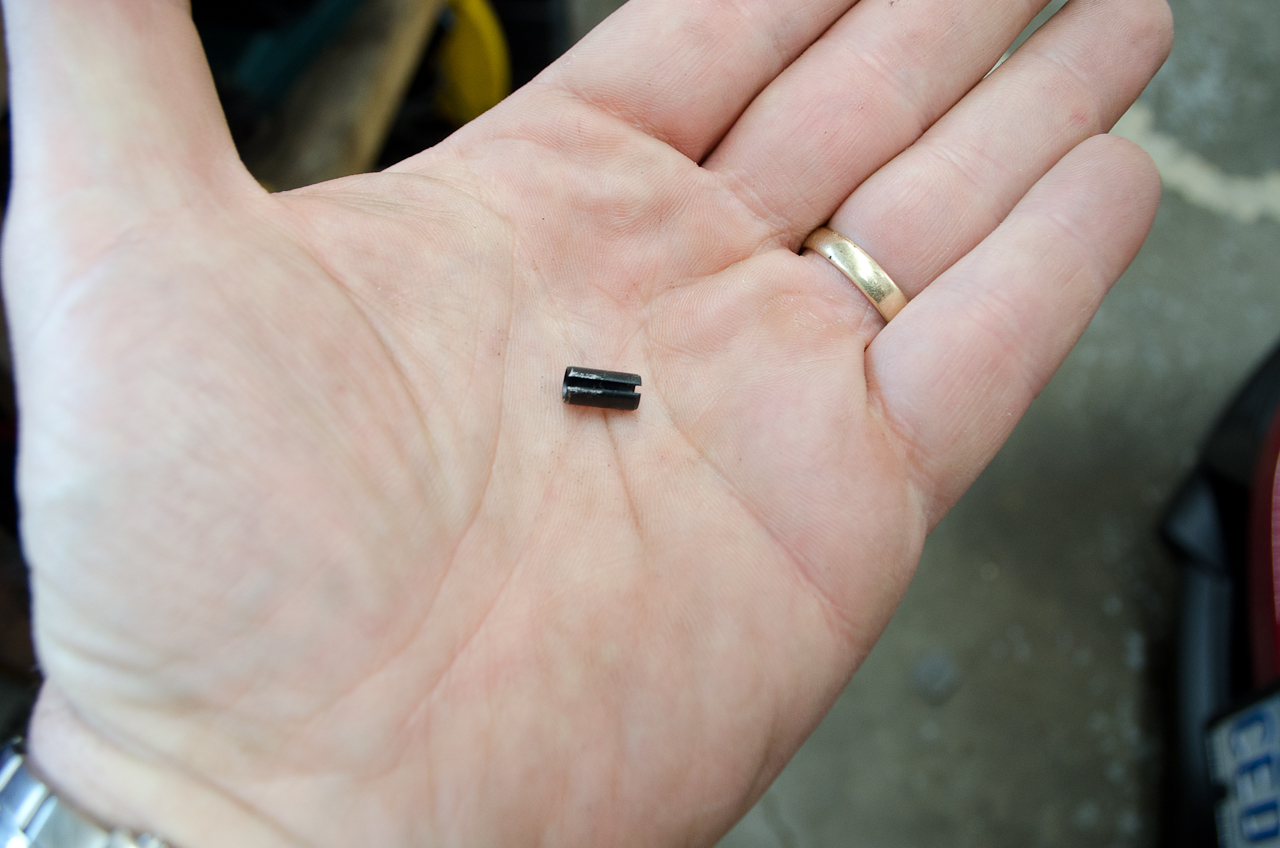 |
It's just a small split pin and can be discarded. |
 |
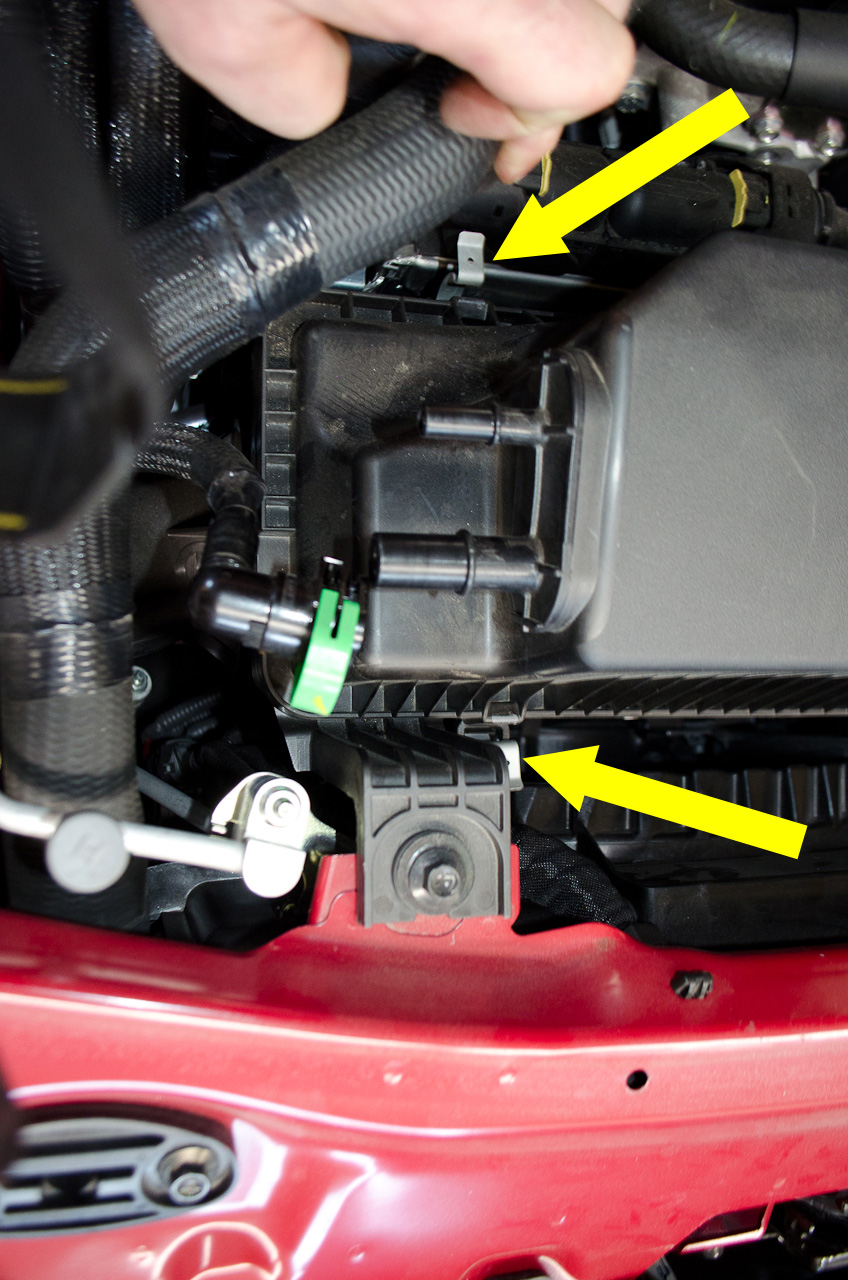
Now move to the right side of the airbox and, using a small flat-bladed screwdriver, gently lever open the blue clip. |
 |
Clip fully opened. |
 |
Then disconnect the Blue Vapour Recovery Hose from the airbox. |
 |
Open the green clip in the same fashion... |
 |
...and disconnect the Green Vapour Recovery Hose from the airbox. |
 |
Next, release the two small clips holding the airbox lid on... |
 |
...and remove the airbox lid. |
 |
You may have to push the coolant hose (yellow arrow) out of the way to get the lid out. |
 |
Part removed. |
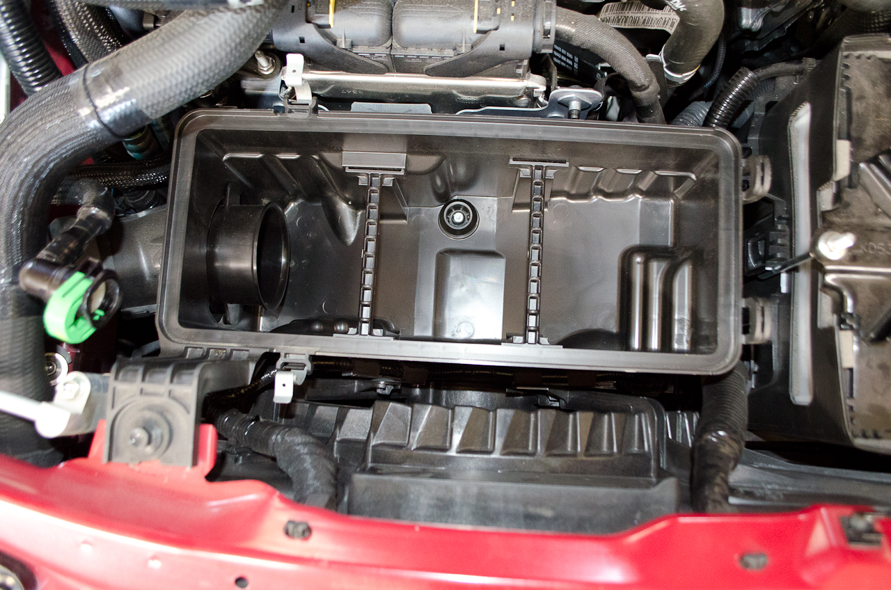 |
Looking down into the empty airbox. |
 |
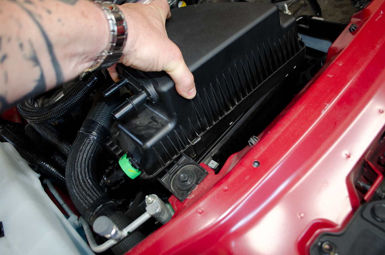
Using a 10mm socket, remove the airbox mounting bolt... |
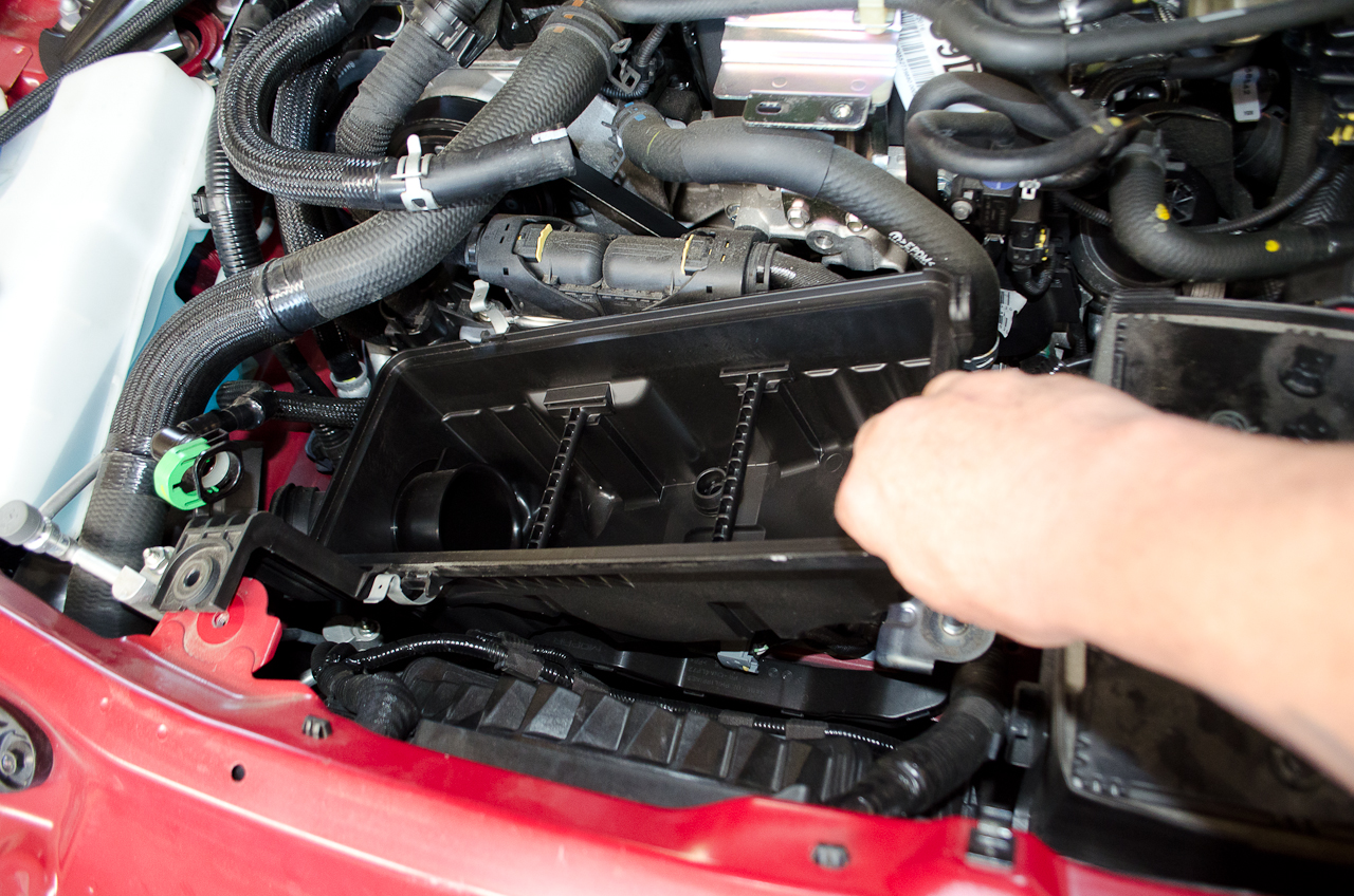 |
...and then remove the airbox. |
 |
Airbox removed. |
 |
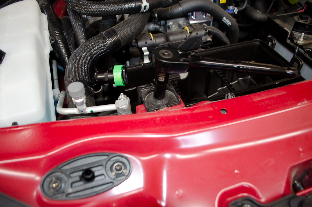
Note the RAM air intake. One end of the EC RAM Air Intake Piece will slip over this lip and be secured with a clamp. |
 |
Look into the engine bay with the airbox removed. |
 |
This is the orientation the RAM Air Intake Piece goes in the car. That is, with the "short" end (the end closest to the EC logo) going over the lip on the RAM air intake in the car. |
 |
Before fitting it to the car, slip a hose clamp over the piece. DO NOT do so in the orientation shown here - it will make it much harder to do up later! Put it on the other way around (shown next). I found it easiest to lube the first half inch or so of the RAM air intake piece before slipping it in place. I like to use Windex as it is plenty slippery and the alcohol makes it evaporate pretty quickly. |
 |
THIS shows the correct orientation for the hose clamp. |
 |
Next, using two more of the supplied large hose clamps, fit the filter into the RAM air intake piece... |
 |
...and then the Intake Piece on the filter. The smaller of the supplied hose clamps goes on the turbo end, and the EC intake Piece should fit flush up on the turbo intake. |
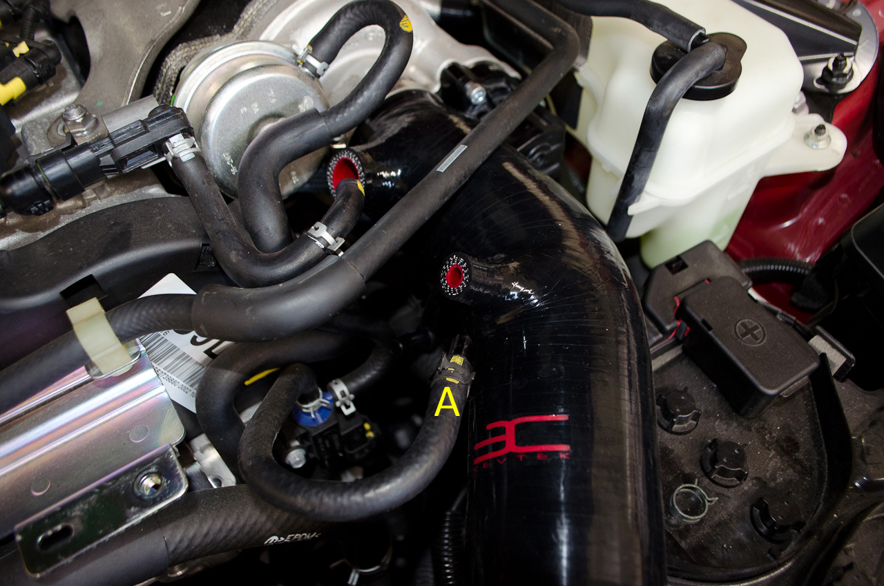 |
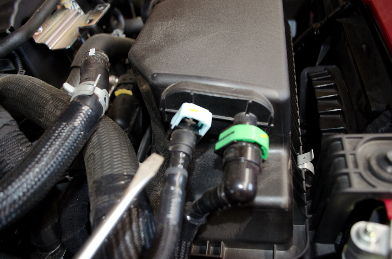
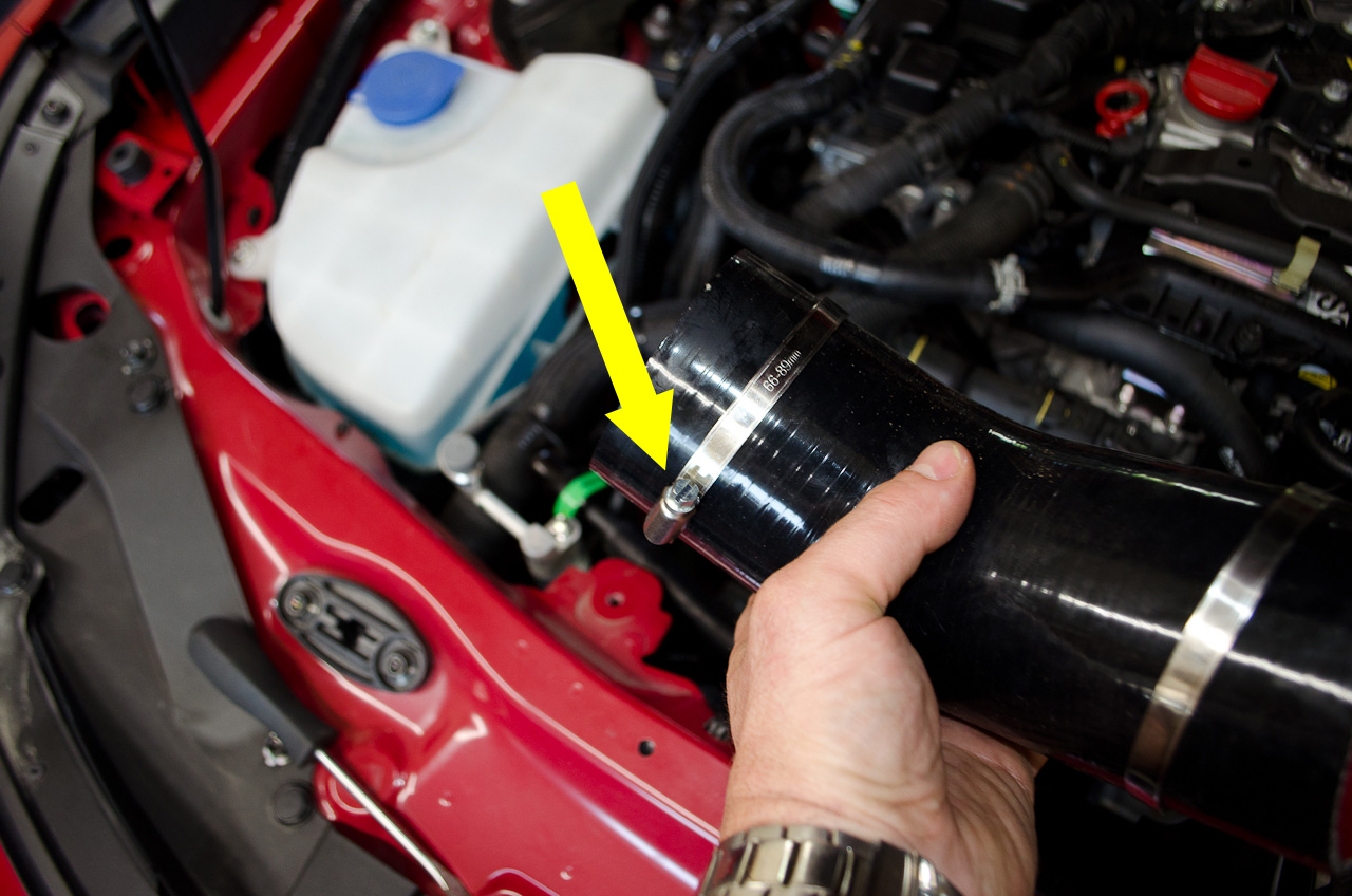
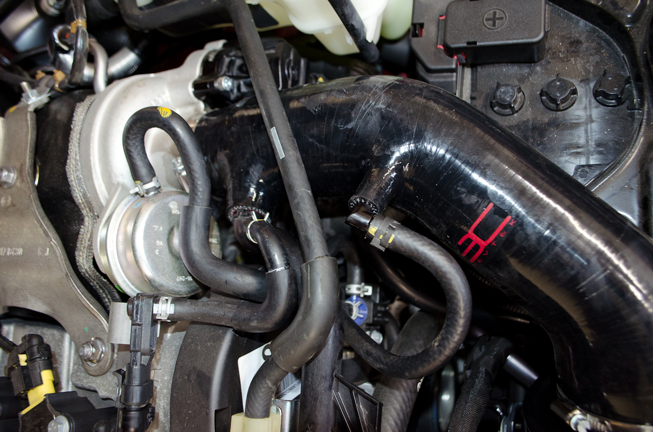
Now it's time to re-make the necessary connections. Fit the end of the Waste Gate Solenoid Valve Recirculation Pipe (A) into the smaller port on the EC Intake Piece... |
 |
...like this. |
 |
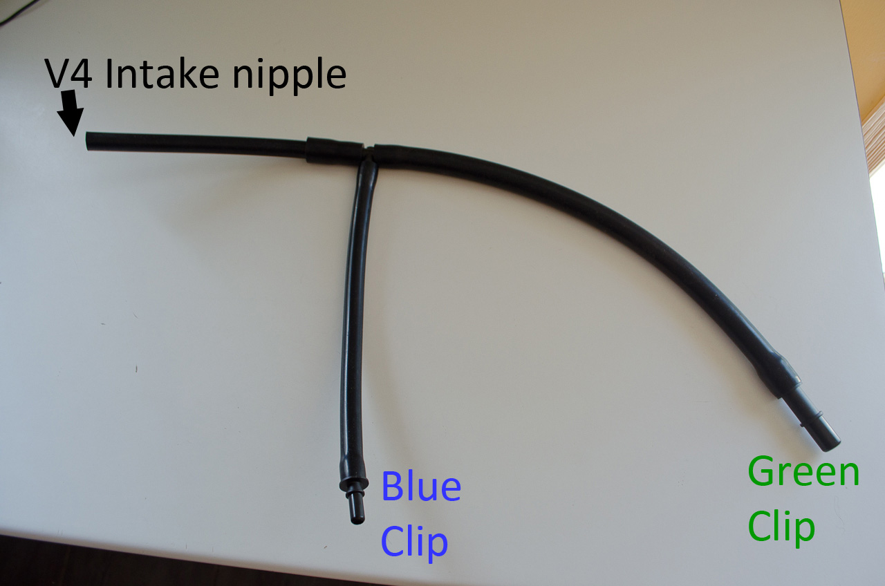
Now, take the supplied vacuum hose T piece and connect the open end to the EC Intake Piece... |
 |
...by slipping it over the little nipple. |
 |
Next, tuck the T piece neatly under the filter and... |
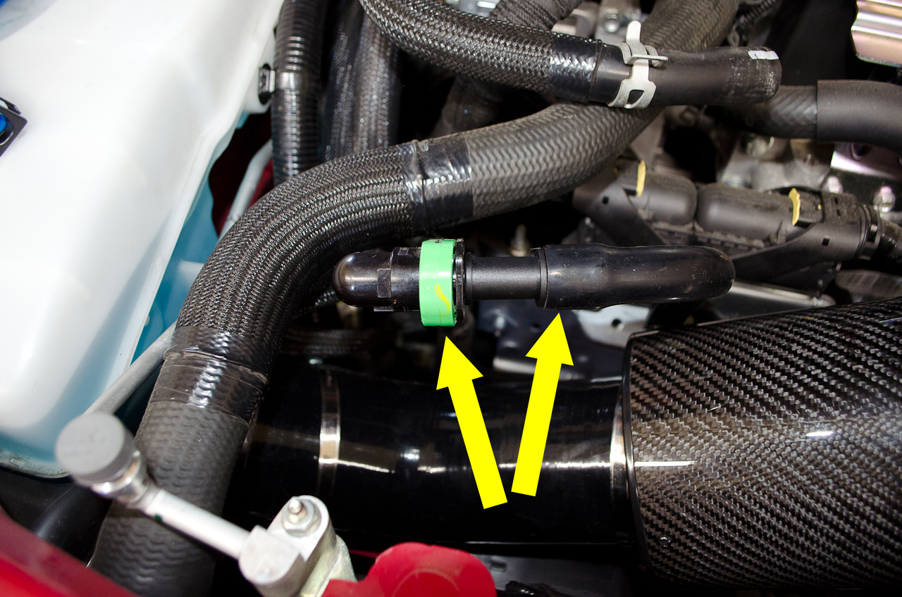 |
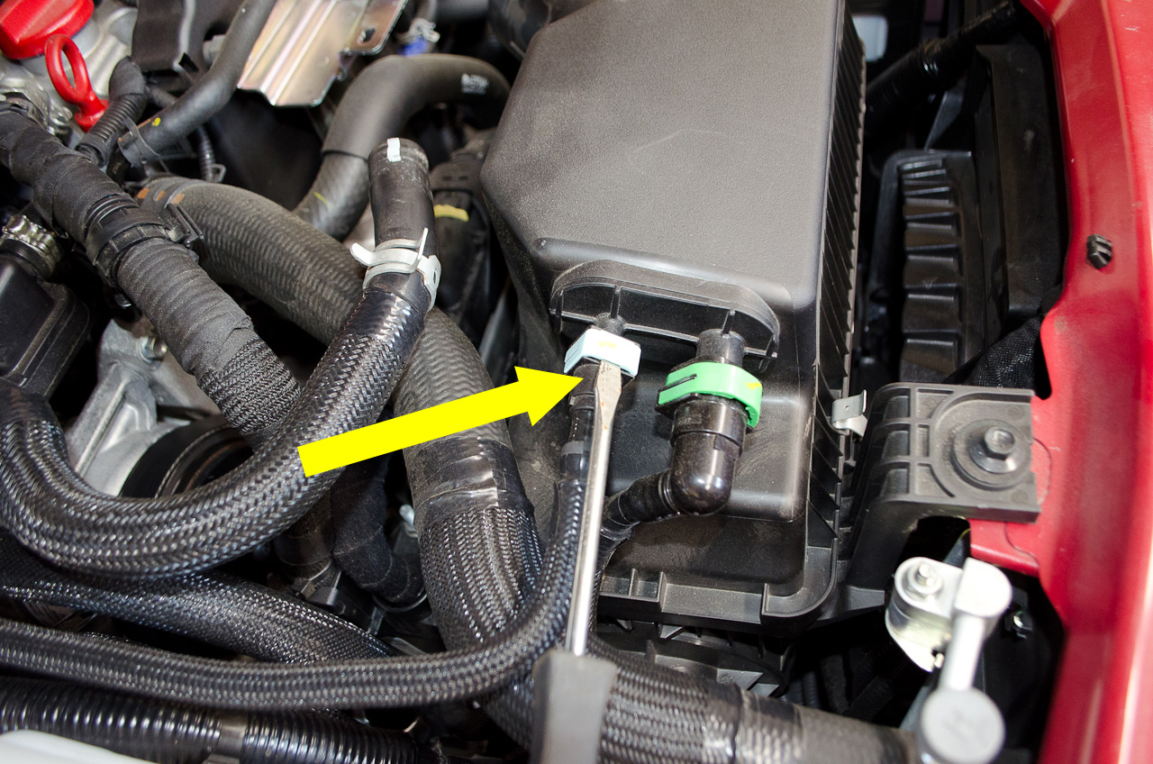
Connect the larger end to the Green clip and push hard to make sure the hose is completely seated, then close the clip. If the clip is hard to close, the hose may not be fully inserted. |
 |
Fully inserted and closed. |
 |
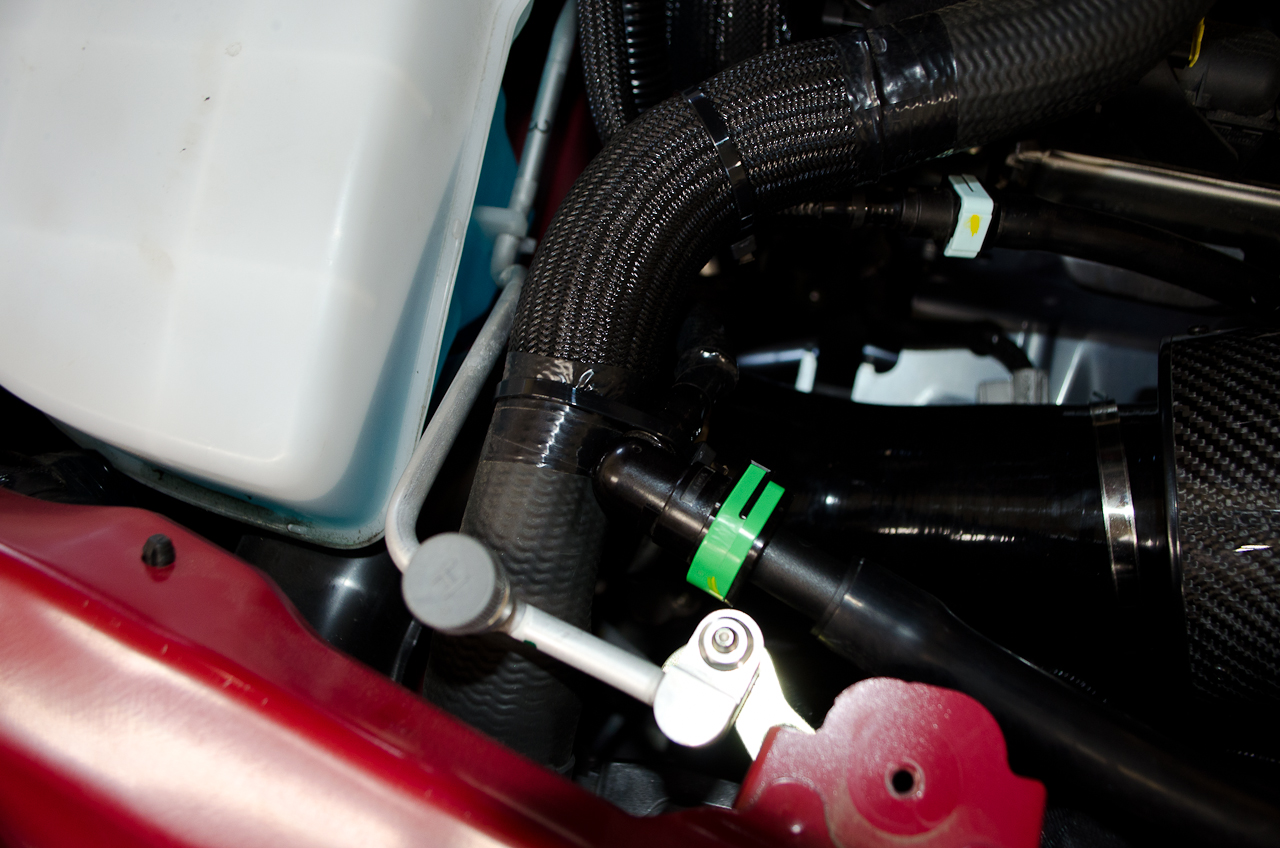
Next, do the same with the smaller end of the supplied T piece and the Blue Clip - making sure everything is fully seated and clips are closed. |
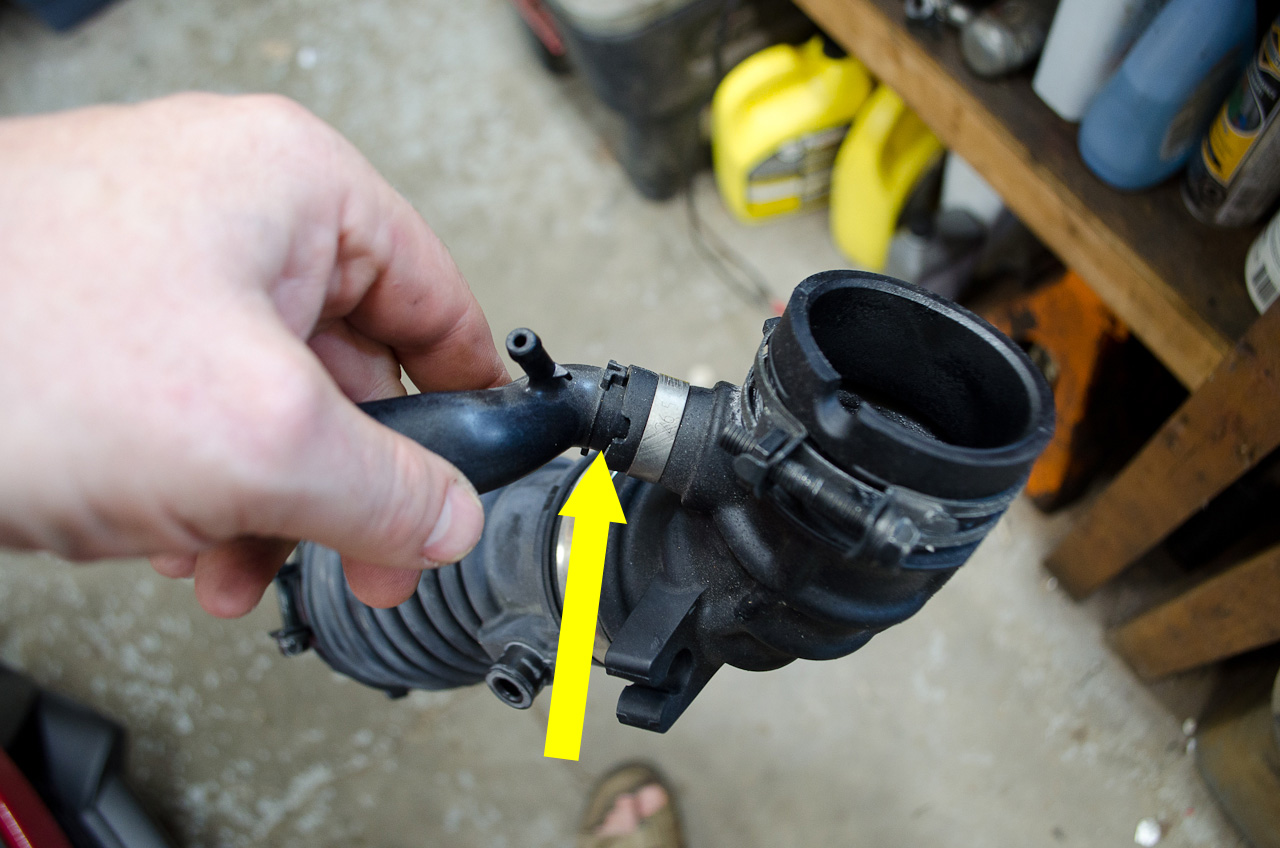 |
Now it's time to return our attention to the Rigid Oil Vapour Pipe. We need to remove it from the Turbo Air Inlet Pipe so we can re-use it. It is secured with a one-time use band instead of a clamp, but it can be removed by grasping both pieces firmly and working them apart with a twisting pulling motion. Use only that force which is necessary and it will come out just fine. |
 |
This is the removed end of the Rigid Oil Vapour Pipe. This will be inserted into the larger of the ports on the EC Intake Piece. |
 |
Here, like this. |
 |
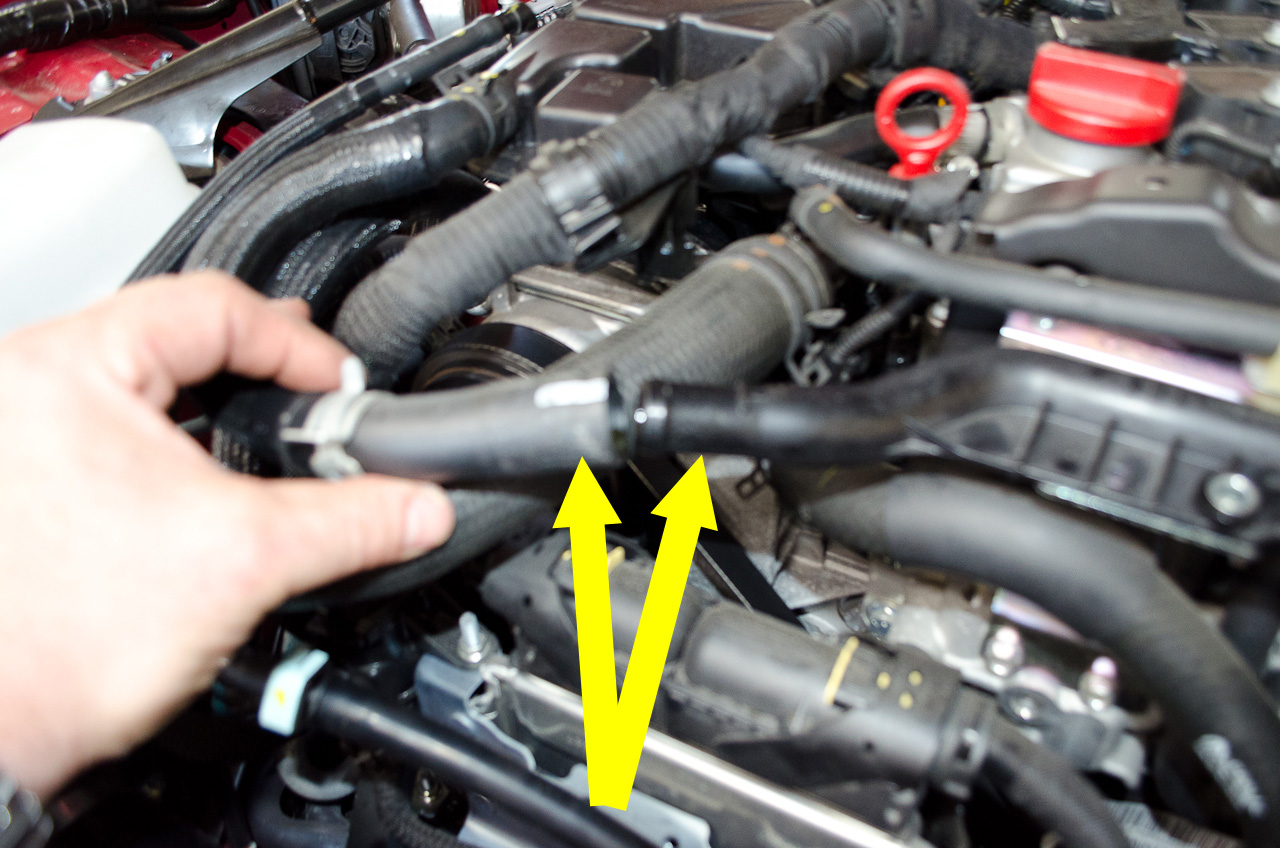
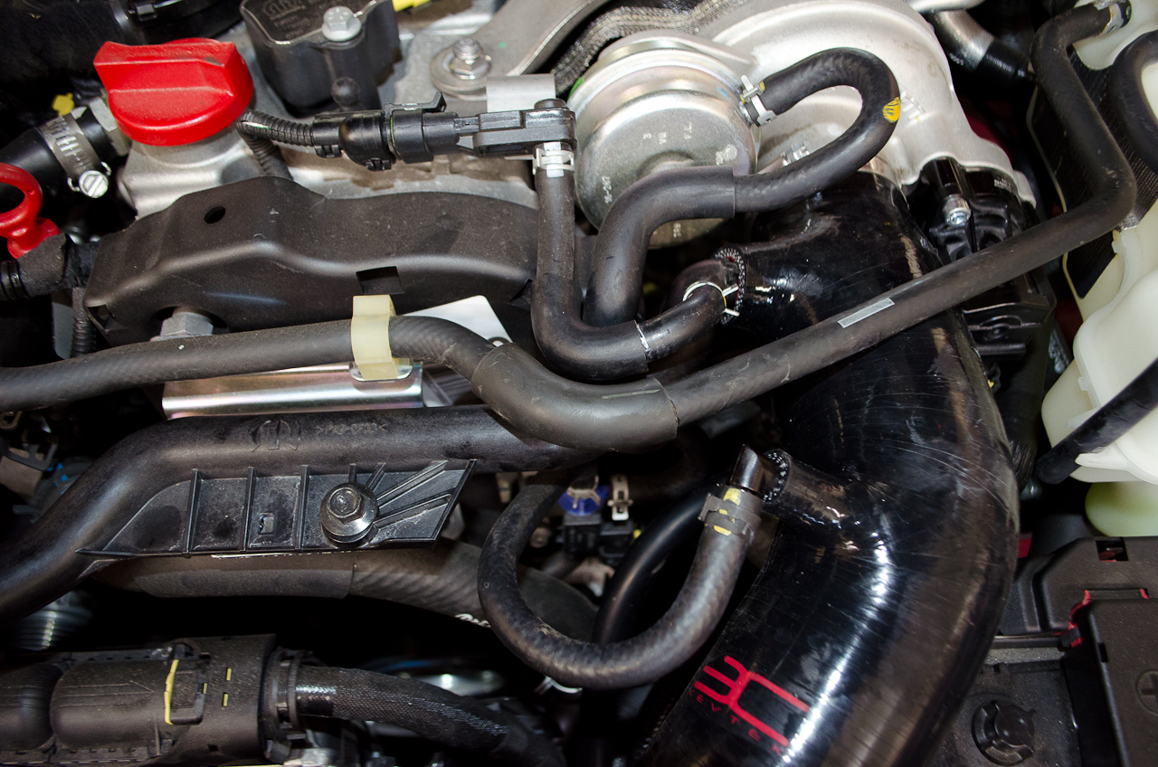
First, tuck it UNDER the coolant hose (yellow arrow) and then insert the end into the Intake Piece firmly and fully. |
 |
Then centre the bolt hole over the threaded hole in its bracket - there is a little locating tab to the left of the bolt hole that will engage when it's in the correct position. |
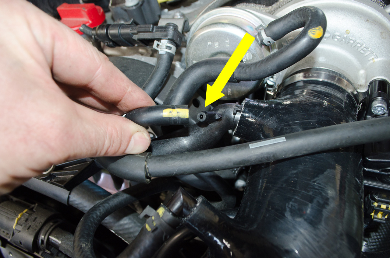 |
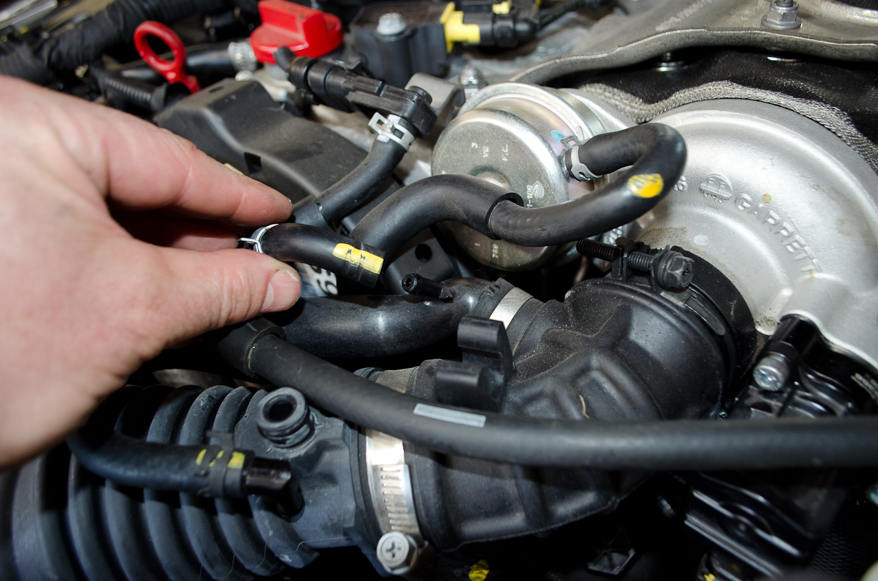
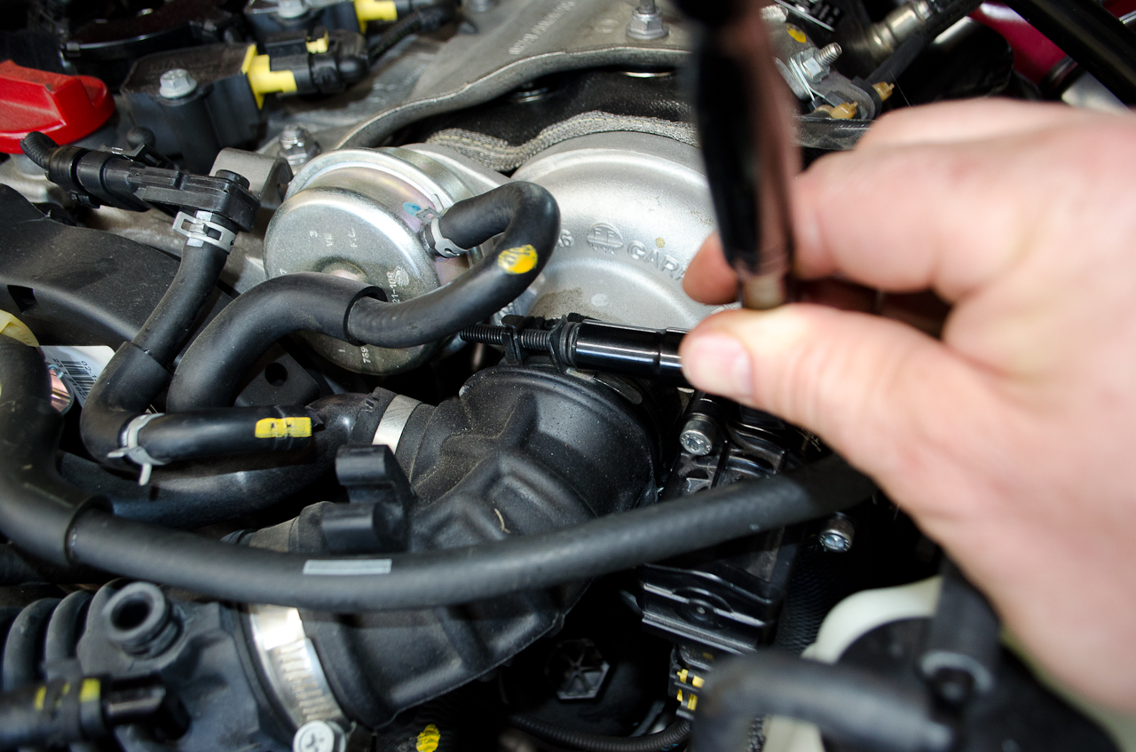
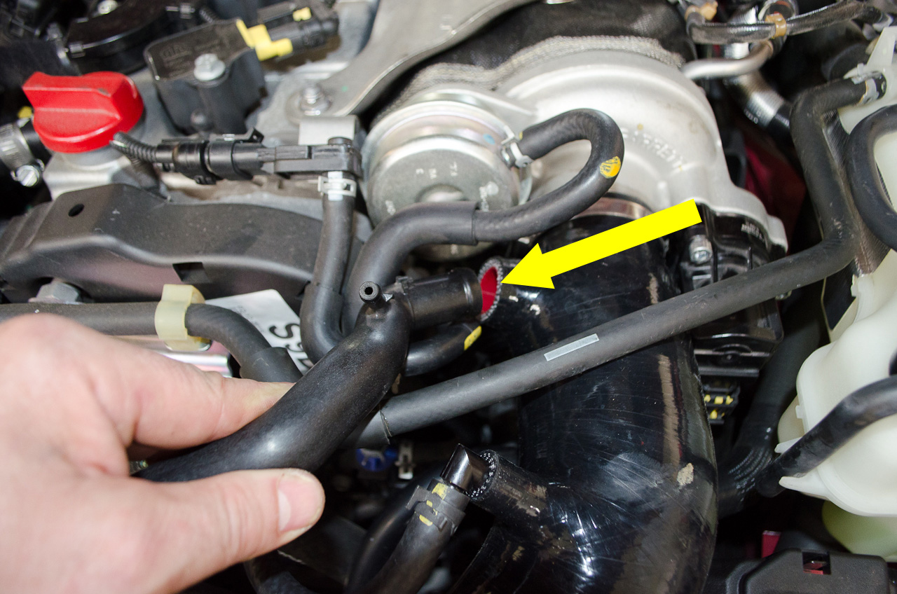
Then connect the Oil Vapour Pressure Sensor Pipe back onto the little nipple on the Rigid Oil Vapour Pipe, like this. |
 |
Next, reconnect the Oil Vapour Pipe to the Rigid Oil Vapour Pipe and reinstall the clamp. |
 |
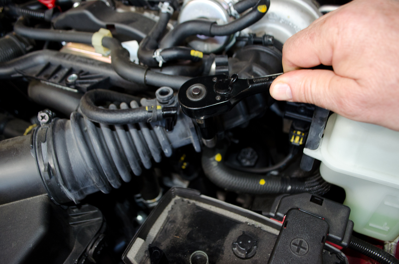
Reinstall and tighten the bolt holding down the Rigid Oil Vapour Pipe. |
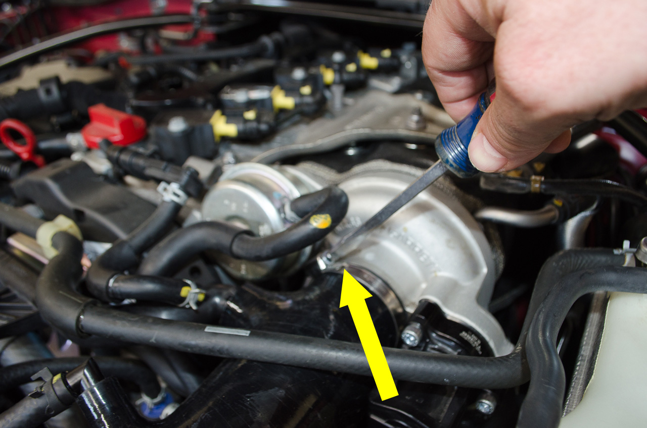 |
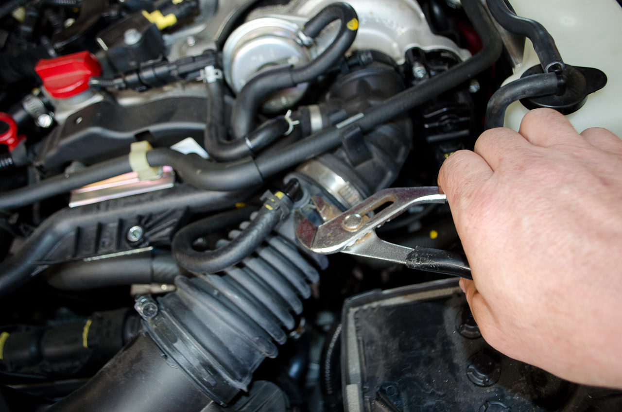
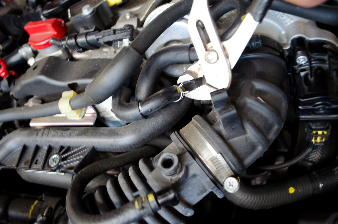
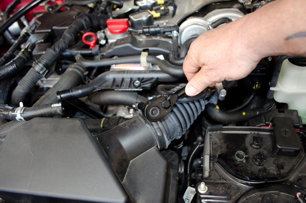
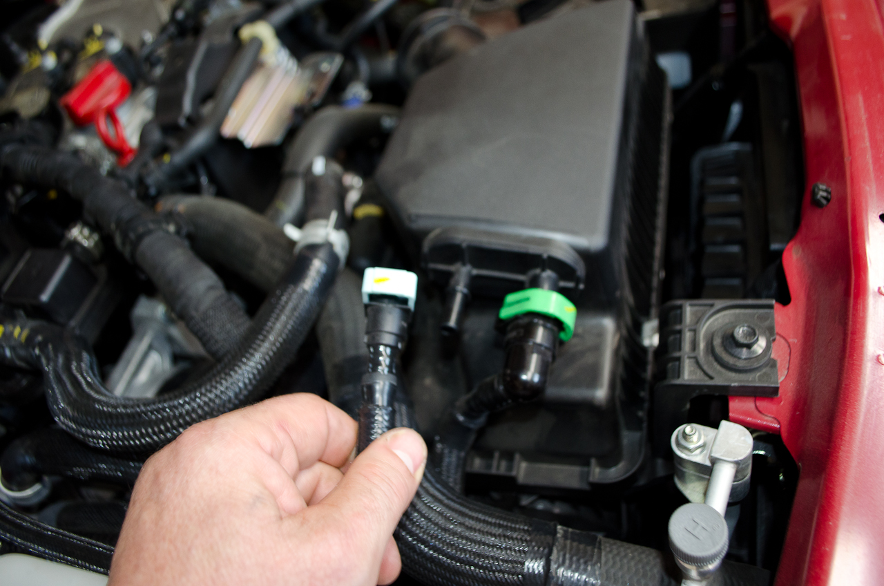
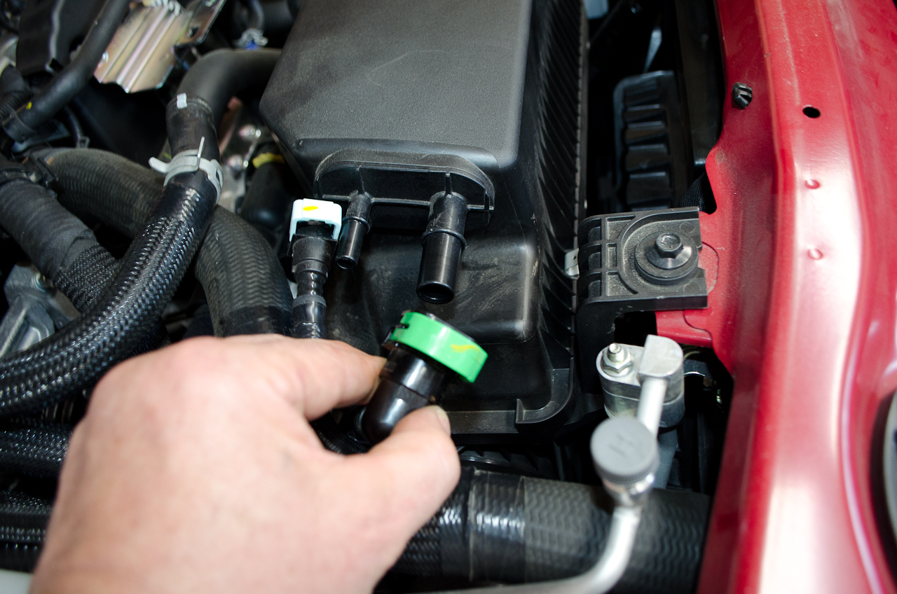
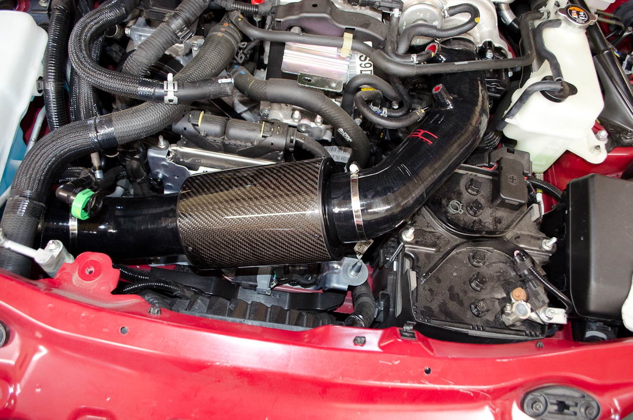
With everything installed and connected, it's time to check all the connections and tighten the hose clamps. Start at the turbo and work backwards. Tighten the turbo clamp |
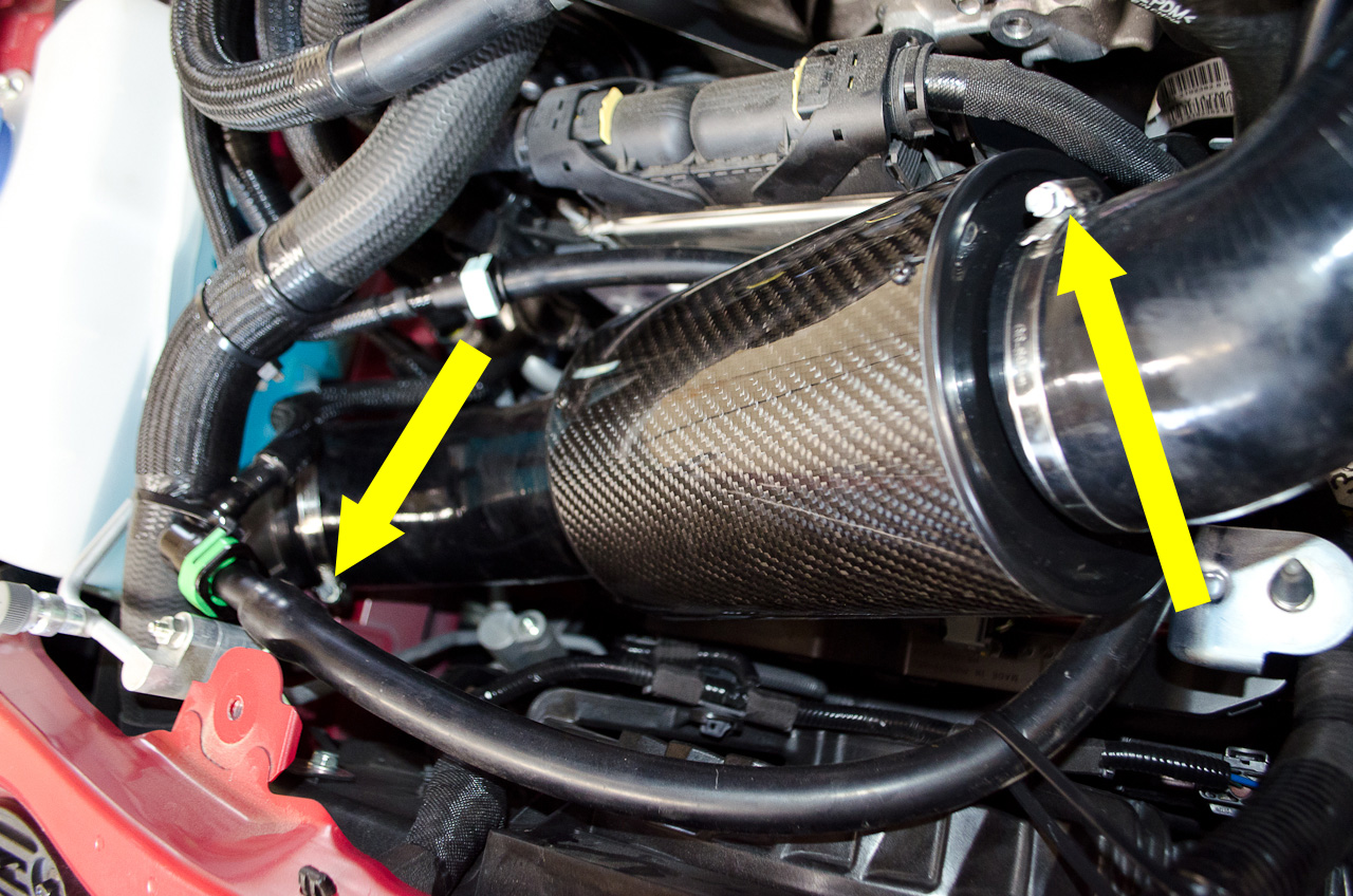 |
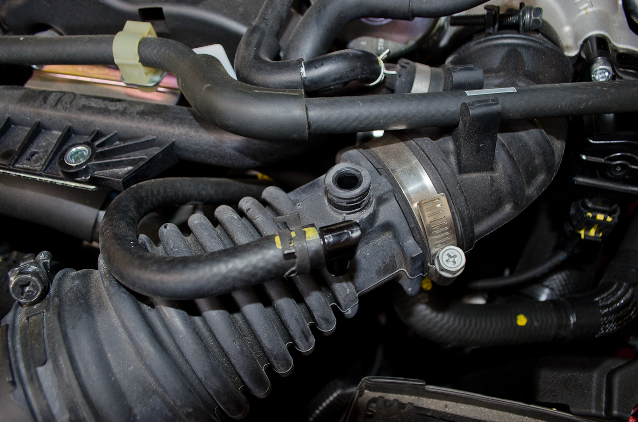
The clamp at each end of the filter cannister (pic only shows one of the filter clamps - sorry) |
 |
And the clamp at the RAM air intake end. |
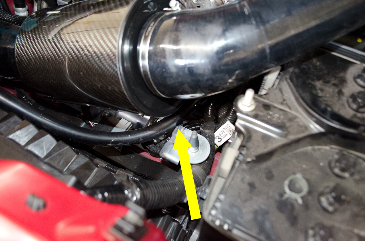 |
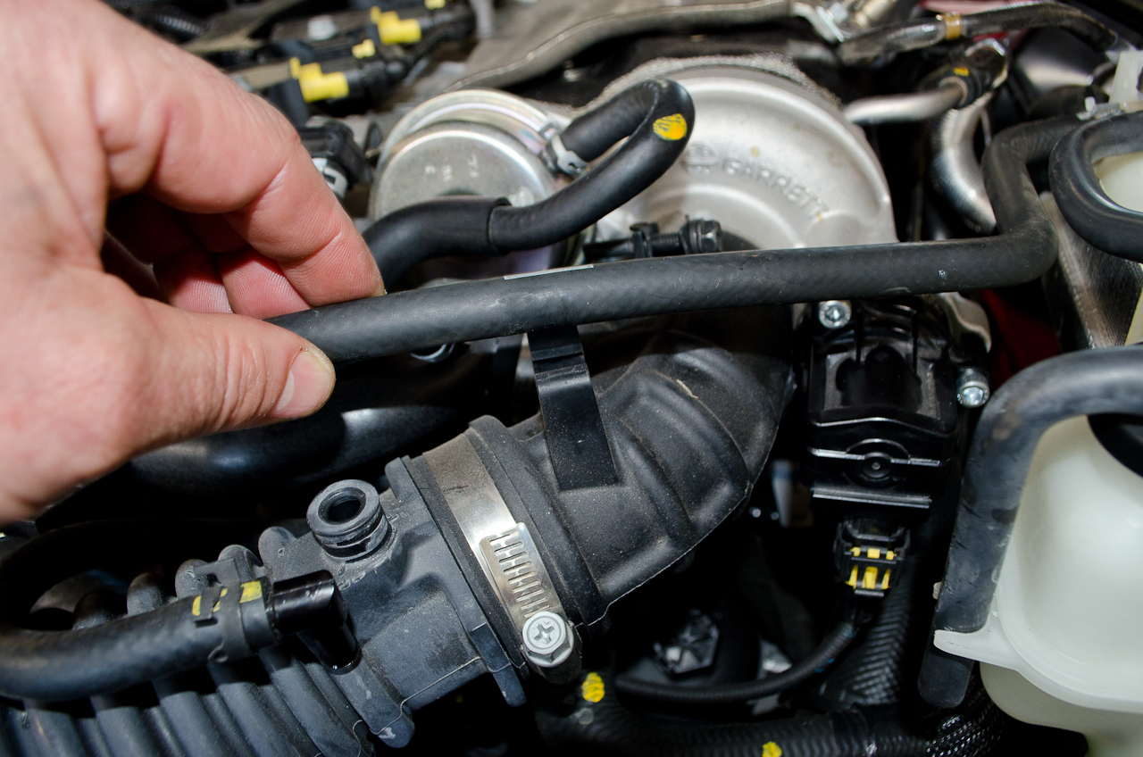
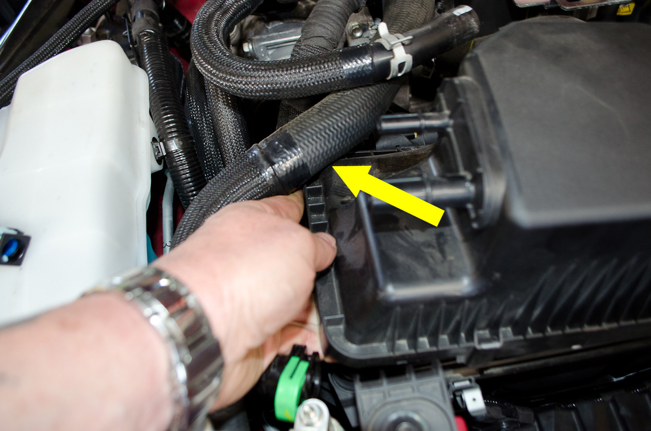
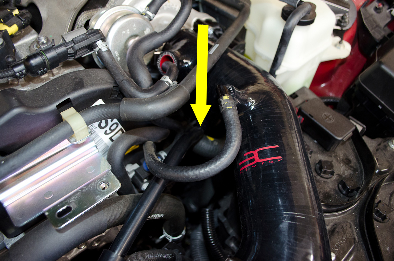
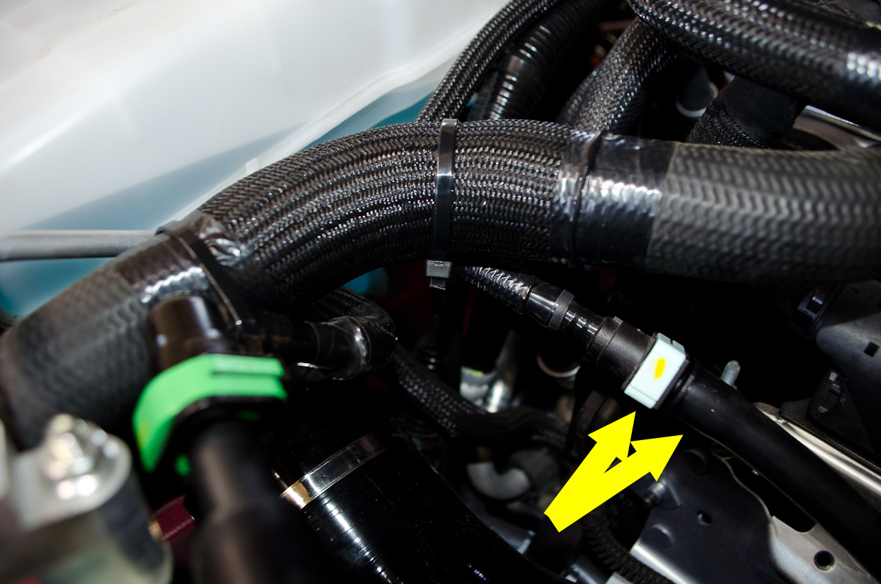
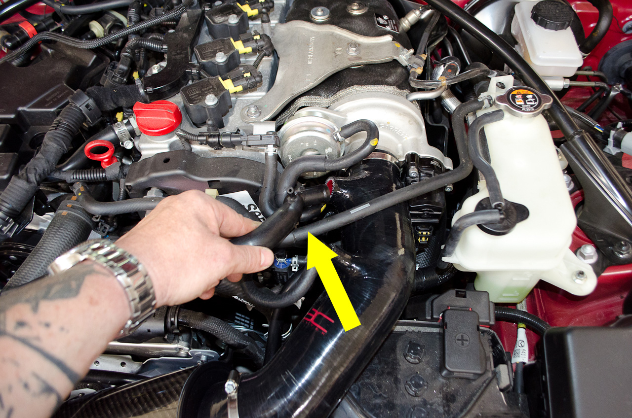
Now do a final check for clearances and routing. I found that the way I had routed the supplied T piece vac hose left it at risk of rubbing against this metal bracket... |
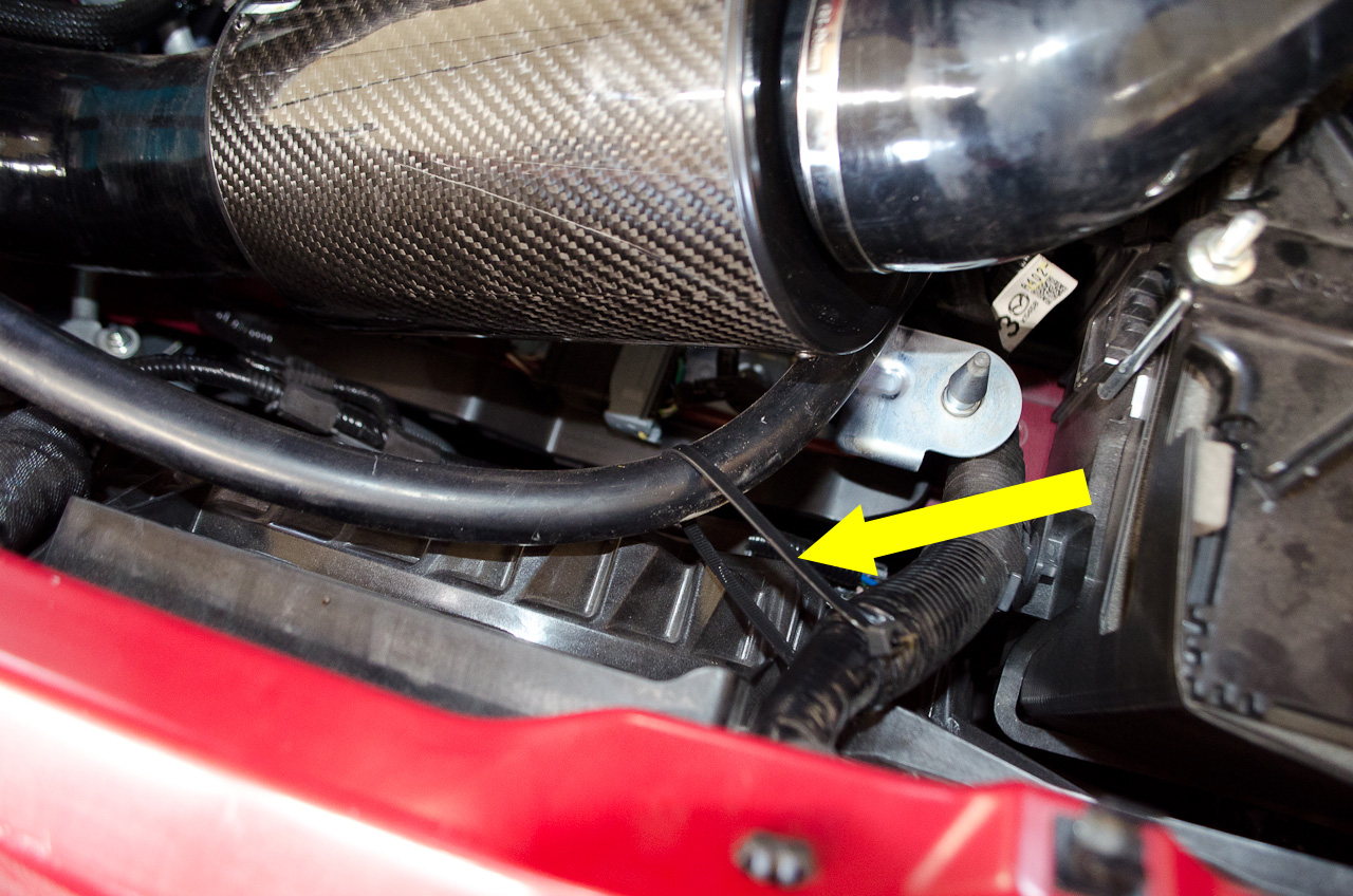 |
...so I secured it with a zip-tie... |
 |
...and solved the problem. |
.jpg) |
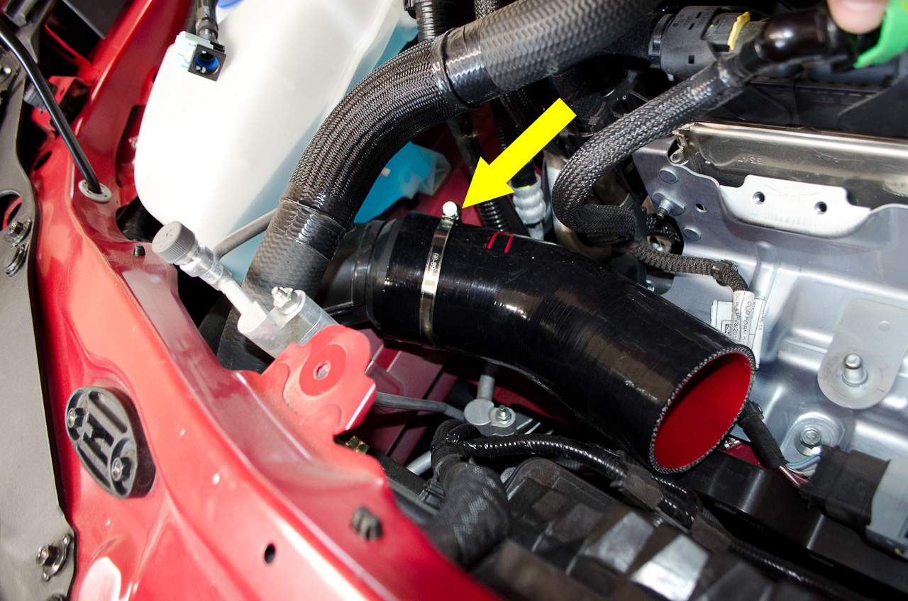
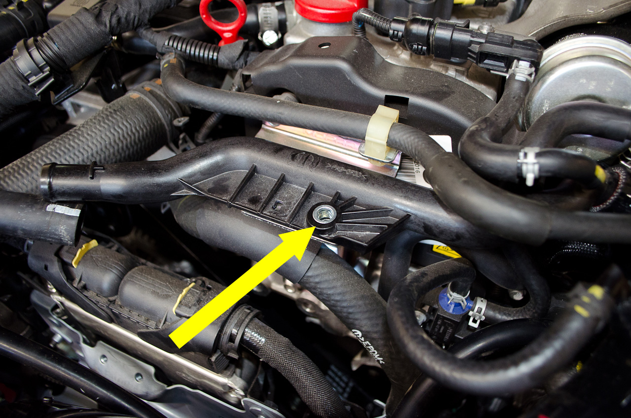
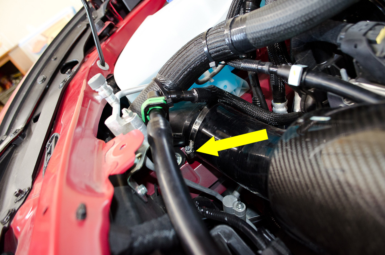
Finally, take the supplied small piece of split hose and slip it over the edge of the battery surround (yellow arrow) to prevent the intake piece from rubbing directly on the surround. |
 |
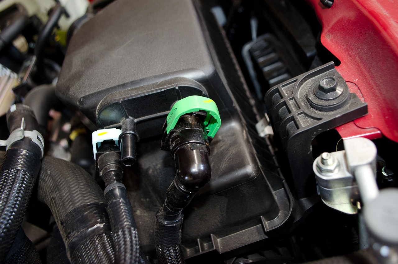
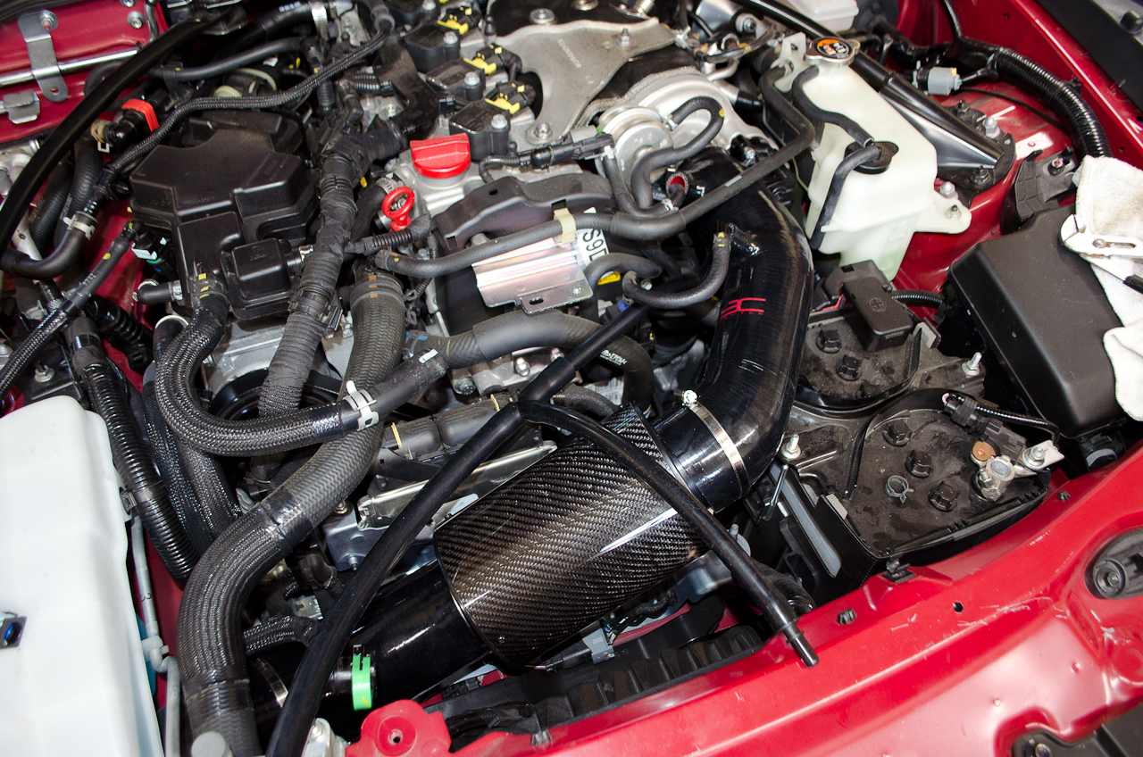
Take one last look to make sure all your connections are correct. |
 |
Everything is where it should be, nothing loose or disconnected... |
 |
Looks good! |
|
Congratulations - you did it! Now go for a drive! |
Additional Information: |
|
|