 |
Fox Air Bumps
By Bill "BillaVista" Ansell |
IntroductionOnce seen only on desert race trucks, air bumps have become extremely popular and are now showing up on all kinds of rigs from rock crawlers to Ultra-4 racers. Here's a look at what's inside an air bump and how to modify their travel to get what you need. |
 |
Basics |
|
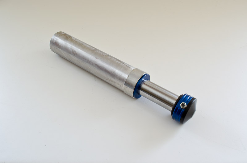 |
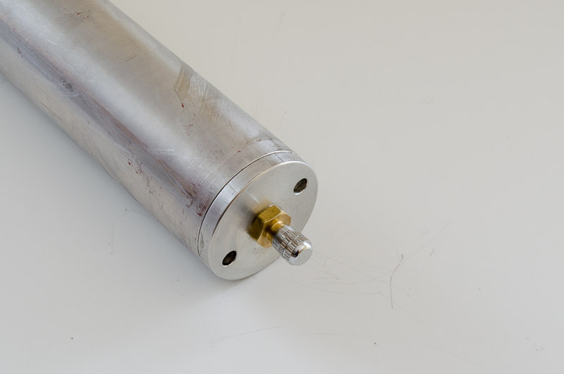
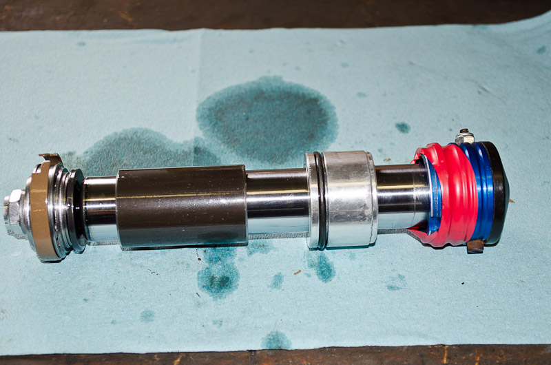
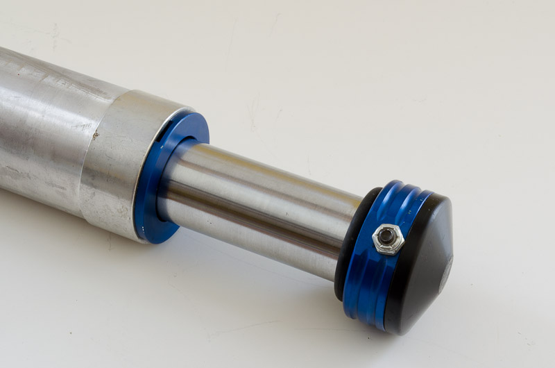
This is a "2.0 series" Fox air bump (meaning the OD of the body is 2.0" ).
|
||||||||||||||
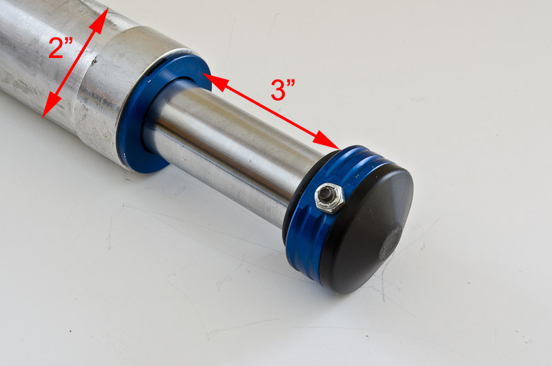 |
This particular one is a 3-inch bump, meaning the travel from fully extended to fully compressed is approximately 3 inches. | ||||||||||||||
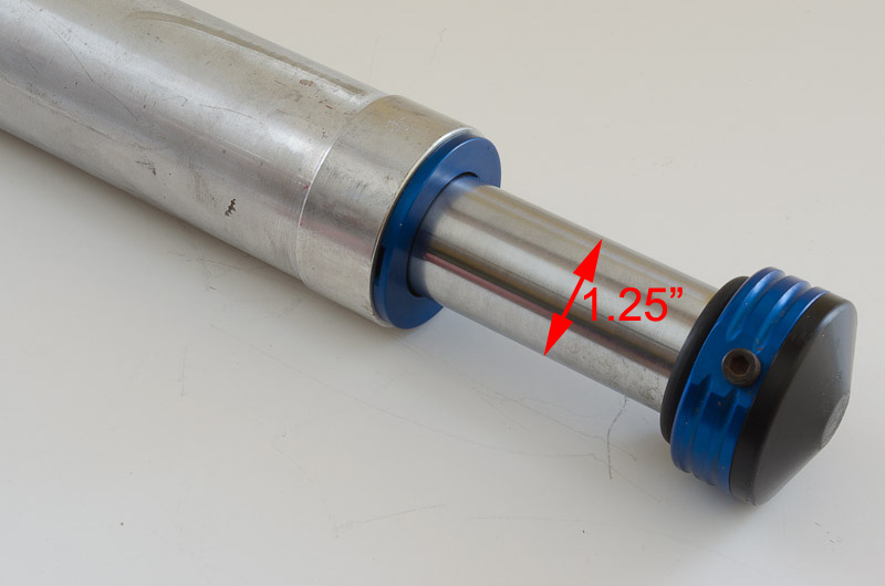 |
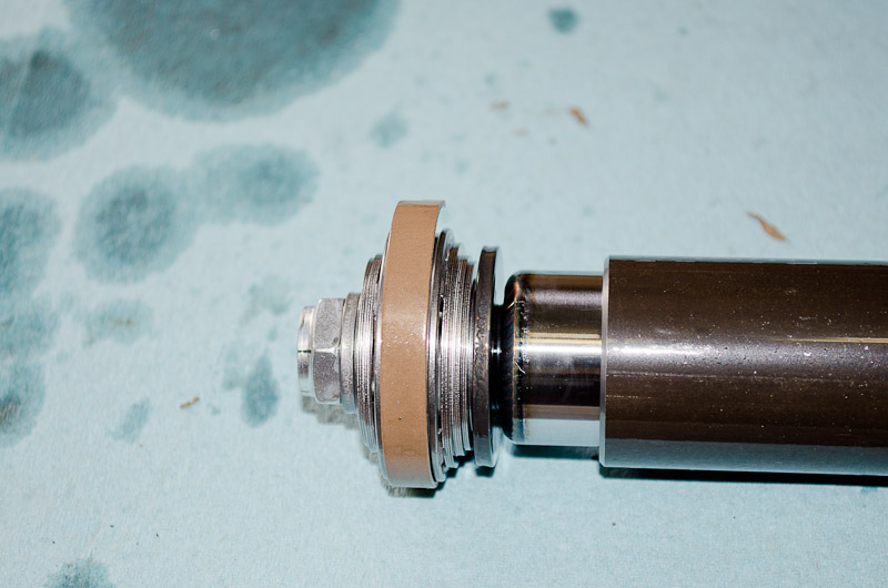
The head of the bumpstop features a replaceable black plastic contact pad secured to the bump with a small Allen head cap screw. On the shaft is a rubber O-ring that serves as a small cushion on full compression. It is approx 7/32" thick and has an ID of 1-1/4", same as the OD of the shaft. |
||||||||||||||
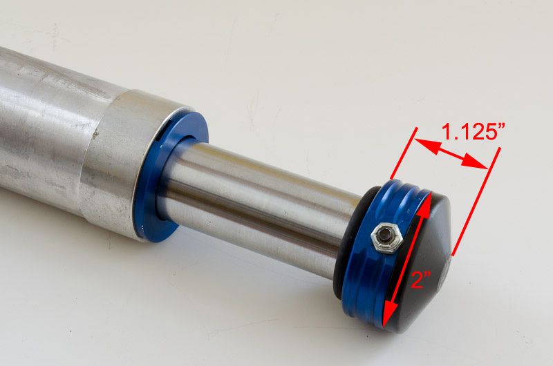 |
The length of the bump head and contact pad is approx. 1-1/8". The OD is 2", same as the body of the bumpstop. The small Allen head cap screw is secured with a locking nut. |
||||||||||||||
 |
Inside, an air bump looks and function very much like an air shock except instead of bolting one end to the chassis and one end to the axle (as with a shock) the body is mounted solidly to the chassis and the shaft end is free to be contacted by the axle as it travels upwards. There is a piston and valving shims on the shaft, and this piston travels up and down through nitrogen-pressurized hydraulic oil contained in the body of the bumpstop. In this manner, the bumpstop damps the up-travel of the axle / wheels before it reaches its hard stop at full bump; and the amount and rate of damping can be tuned by adjusting the valving (like in a coilover shock) and the nitrogen pressure (like in an airshock). |
||||||||||||||
 |
At the other end of the bumpstop their is a Schrader valve which is used to charge the bumpstop with nitrogen, in the same way an air shock is charged. The nitrogen charge serves three purposes:
|
||||||||||||||
* For those interested in a little more detail on the issue of gas charging to minimize aeration and foaming of the hydraulic fluid, it works like this: When the bumpstop cycles, the motion of the piston through the oil creates an area of high pressure ahead of the piston and an area of low pressure behind it. If the pressure of a fluid is reduced below its vapour pressure, the fluid will spontaneously change state from a liquid to a gas. This means that tiny air bubbles can form in the low-pressure area directly behind the piston. This process is called cavitation. Left unchecked, the tiny air bubbles that form will mix with the oil - a process called aeration. The resultant mixture of oil and air inhibits the functioning of the bumpstop because the piston and valving are designed to produce the required damping by operating in a column of incompressible oil, not in a column of frothy air and oil. Once the oil is mixed with air, or aerated, it is no longer incompressible. The faster the piston pumps up and down, the more rapidly cavitation aerates the oil on both sides of the piston, and eventually the oil will be churned into foam. The resulting foam offers little resistance and causes extreme fade of the bumpstop’s damping ability. The addition of pressurized nitrogen gas to the shock helps to prevent the low-pressure zone behind the moving piston from falling below the vapour pressure of the oil, reducing the chance of cavitation, aeration, foaming, and eventual fade. |
|||||||||||||||
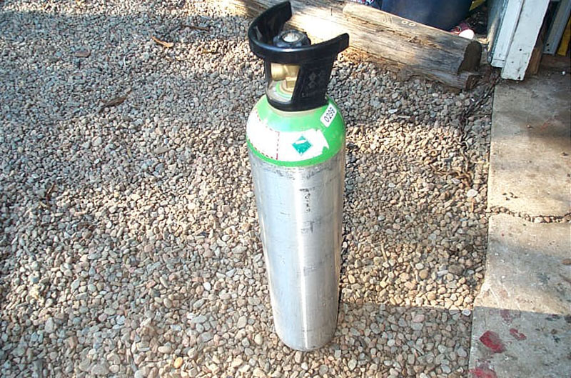 |
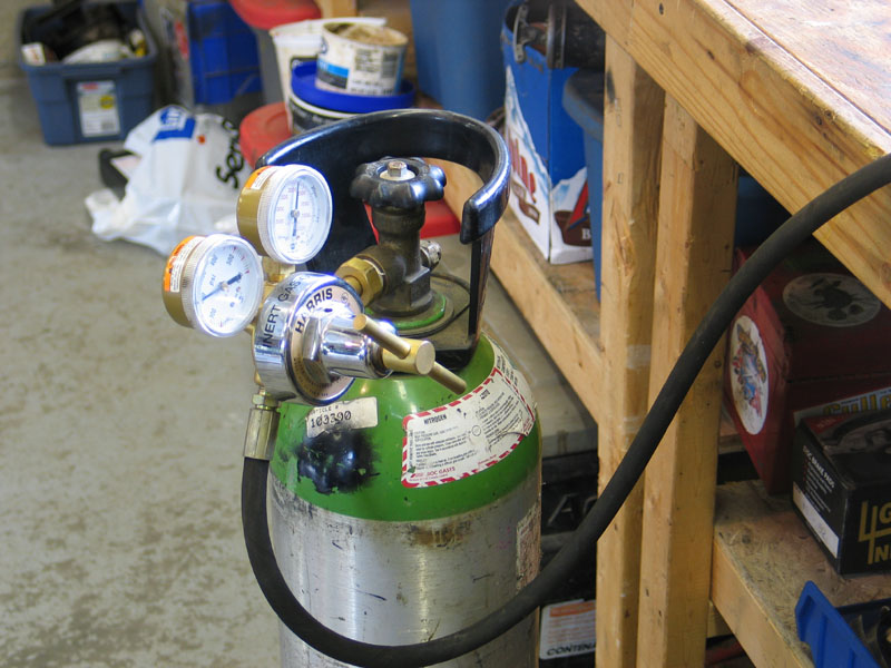
To charge an air bump (why don't we call them nitrogen bumps?) you will need a nitrogen tank, like the one pictured at left. They are available from welding gas suppliers.
DO NOT use air or CO2 or any other gas. Nitrogen is specifically used due to its thermal stability and the fact that its non-hygroscopic. That means it doesn't contain moisture (water vapour) like air does and it doesn't expand and contract with temperature as much as other gasses. This is important because moisture inside the bumpstop can cause corrosion. Also, excessive expansion of the gas will change the pressure of the gas and therefore alter the bumpstop's performance as it heats up and cools down. |
||||||||||||||
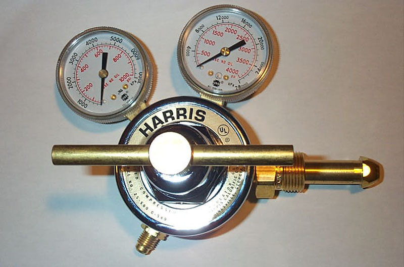 |
You will also need a nitrogen specific regulator, like this one... | ||||||||||||||
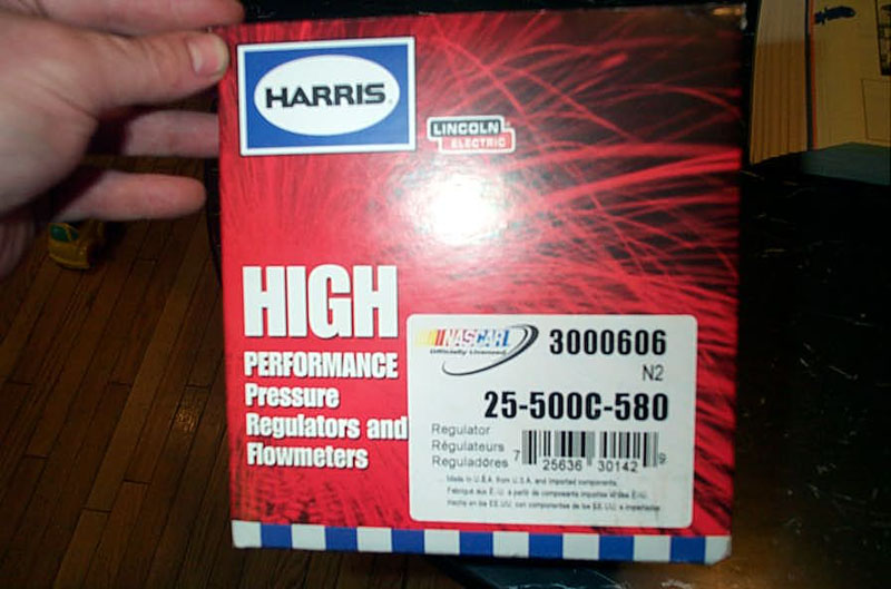 |
...that came in this box. | ||||||||||||||
 |
If you're assembling your own nitrogen charging setup, be sure to also use a high-pressure hose and not some flimsy plastic hose, as the pressure in the tank can be upwards of 2000 psi. I used a 2-wire hydraulic hose. Of course, you will use the regulator to adjust the working pressure down way below the tank's 2000psi. |
||||||||||||||
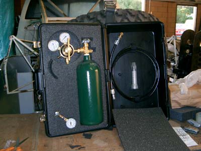 |
If it's a pain for you to assemble your own nitrogen charging system (the regulator's, particularly, can be hard to find and expensive), pre-made kits are available. This kit from Poly Performance is a complete shock servicing kit that includes all the nitrogen equipment, plus a plastic oil syringe, all in a handy foam-lined case. |
||||||||||||||
Customizing TravelOne of the things you may or will want to do when installing air bumps is to adjust the travel. The 2.0 series are sold in 3" or 4" travel versions, but as we shall see shortly - they are exactly the same except for one internal component - the internal spacer on the shaft. Also, depending on your rig, type of driving, suspension setup, etc., it's possible that 3" may be too long or 4" too short. The nice thing is, you can simply and easily convert either of them to anything from 0 - 5-3/8" travel. But, in order to do that, first we have to take it apart. |
|||||||||||||||
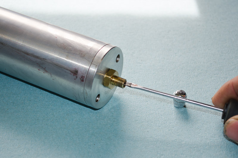 |
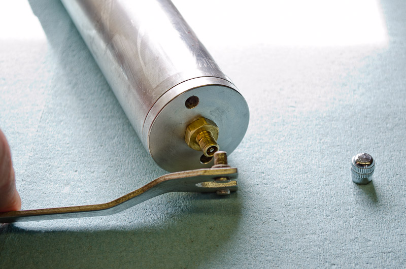
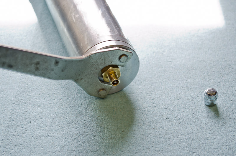
Start by using a small screwdriver or pick to release the pressure via the Schrader valve. Then, using a valve-core removal tool, remove the valve core from Schrader valve (hold the valve up when you do this). |
||||||||||||||
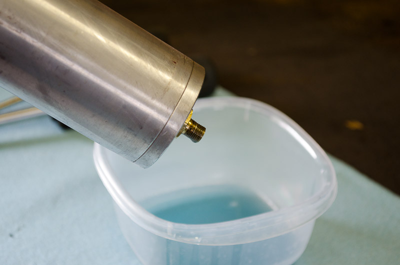 |
With the core removed, carefully pump the bumpstop over a clean container to empty the shock oil. The capacity of the 3" bumpstop is about 105cc. (105ml). If you are careful and keep things clean, you should be able to re-use the oil without having to purchase more. However, if you do need more, it is 5wt shock oil. |
||||||||||||||
 |
With the fluid removed, use a small screwdriver to pry off the dust cap... | ||||||||||||||
 |
...like this. | ||||||||||||||
 |
I used a piece of red electrical tape to hold the dust cap to the head, out of the way. | ||||||||||||||
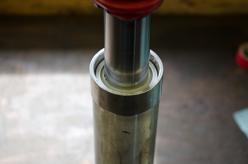 |
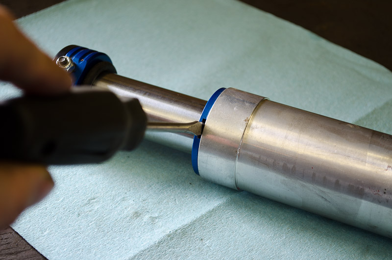
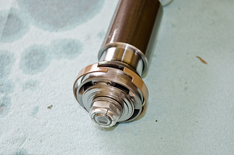
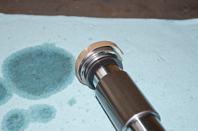
With the dust cap removed you can see the bearing (shaft guide) and shaft seal inside the body of the bumpstop. Using a soft wooden or plastic tool, tap the bearing down to expose the snap ring (it can take quite a bit of force)... |
||||||||||||||
 |
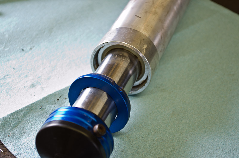
...shown here. Next, using a pick or screwdriver, carefully remove the snap ring, being careful not to scratch the shaft. | ||||||||||||||
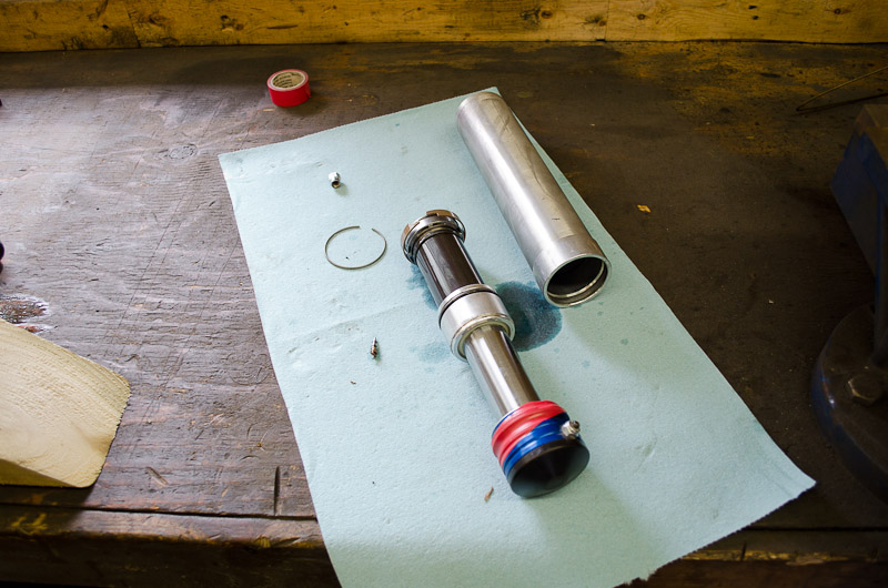 |
With the snap ring removed, you can remove the shaft and internals from the body of the bumpstop Grasp the head and gently rock the shaft back and forth while drawing it out of the body. When it comes out, lay the components out on a clean surface. Note the similarities between the bumpstop and an airshock or even a coilover shock. |
||||||||||||||
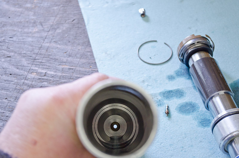 |
The inside of the body, looking down at the inside of the end-cap. | ||||||||||||||
 |
There's really no reason to ever remove this cap, but if you have to... | ||||||||||||||
 |
...I discovered that a wrench for a standard 4.5" angle grinder fits perfectly. | ||||||||||||||
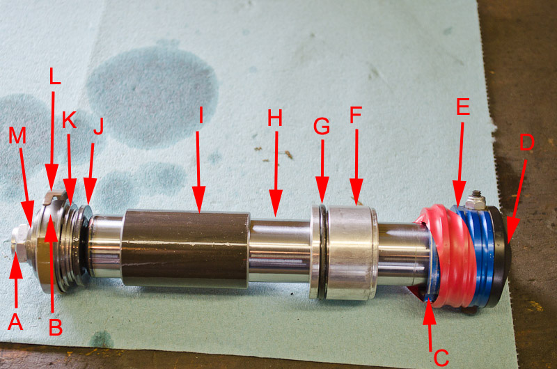 |
The shaft and internal components:
|
||||||||||||||
|
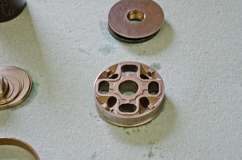
Close-up view of the piston and shims. | ||||||||||||||
 |
Good view of the rebound shims. Of course, these Fox Air Bumps can be tuned for compression and rebound damping by altering the shim stacks, just the same way an airshock or coilover shock can - but that's beyond the scope of this article. Now that we have everything apart we can get back to the topic of how to custom-tune the length or travel of the bumpstops. |
||||||||||||||
 |
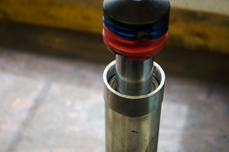
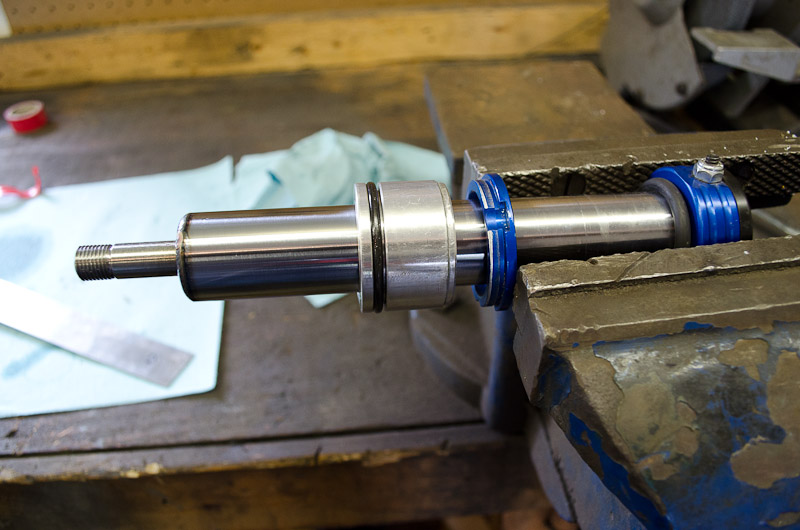
It should be obvious, by looking at the picture, that the length of the internal shaft spacer determines how much the bumpstop extends (i.e. how much shaft is visible when the bumpstop is at rest and not being compressed). As the shaft extends from the bumpstop (caused by the nitrogen pressure acting on the tip of the shaft, the nut, and to some extent the rebound shims and piston) it stops when the spacer occupies all the space between the extension washer and the bearing... |
||||||||||||||
 |
...as shown here. Recall, the bearing is held in a fixed position in the body of the bumpstop. So, obviously, when the shaft has extended to the point that the spacer takes up all the space between the extension washer and the bearing, the shaft can extend no further. |
||||||||||||||
 |
It stands to reason then, that if we make the spacer longer, the shaft can extend less, and we have, in effect, made a "shorter travel" bumpstop. That is, we could lengthen the internal spacer and turn a 4" bump into a 3" bump, or a 3" into a 2", etc. Also, then, if we were to make the internal spacer shorter, the shaft could extend further, and we would have, in effect, made a "longer travel" bumpstop. So we could turn a 4" bump into a 5" bump, or a 3" bump into a 4 or 4.5 or 5" bump, etc. Pic shows the internal spacer on the shaft and the underside of the extension washer that bears against it. So, by varying the length of the internal spacer, you take and 2.0 series bumpstop and make it anything from a 0" up to about a 5-3/8" bumpstop. |
||||||||||||||
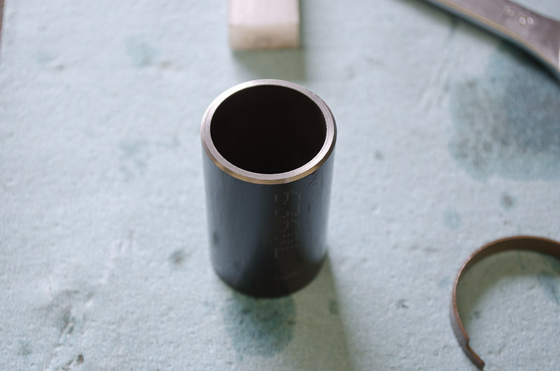 |
This is the internal spacer removed. The cool thing is, it is nothing more than a piece of 1.5" OD, 0.120" wall DOM tubing with the inside machined out to about 1-9/32" to ensure it slides smoothly on the 1-1/4" shaft. So, it is therefore very easy to make, or have made, any length internal spacer you desire. You can even stack multiple spacers of various lengths together to get the total length you need. The stock spacer in a 3" bump is 2-3/8" long. In a 4" bump it is, obviously, 1-3/8" long. In fact, that is the only difference between a 3" and a 4" bump! (that's why 2.5", 3" and 4" bumps all cost the same). If you can't or don't want to make your own, they are available from Fox and good retailers such as Polyperformance in standard lengths (usually in one-inch increments). |
||||||||||||||
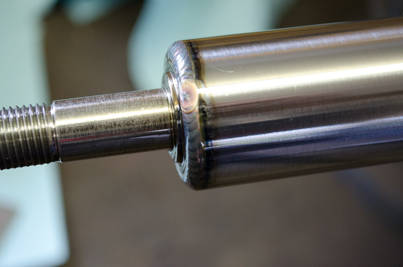 |
Don't know what this was supposed to show - I may have been impressed / distracted by the fancy TIG weld! | ||||||||||||||
 |
To change the internal spacer, you first have to remove the locknut, valving shims, and piston; them slide the spacer off the shaft. Make sure you keep the shims together, in the proper order, and lay them out so you reinstall them facing the correct way. |
||||||||||||||
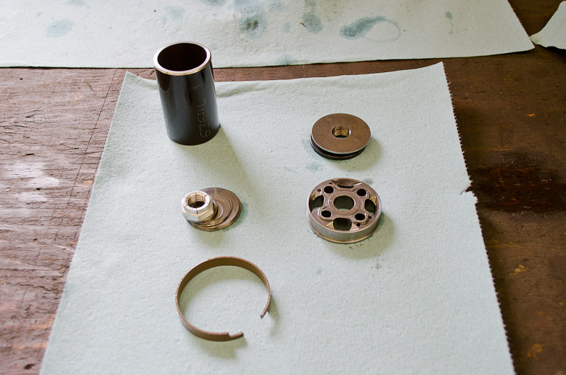 |
Removed components. Clock wise from top, left we have:
|
||||||||||||||
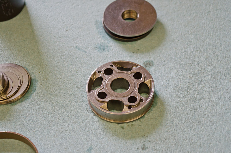 |
Piston, compression-side up. I didn't do a precise inventory, but one thing that struck me was the large number of valving shims compared to a coilover shock (meaning the bumpstop is valved much stiffer). Also, the piston design is quite different compared to a coilover shock. |
||||||||||||||
 |
Piston, rebound-side up. | ||||||||||||||
|
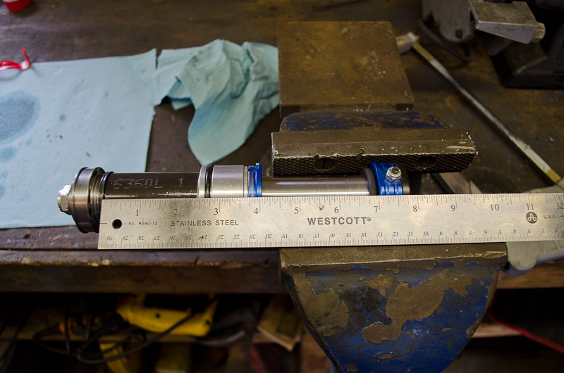
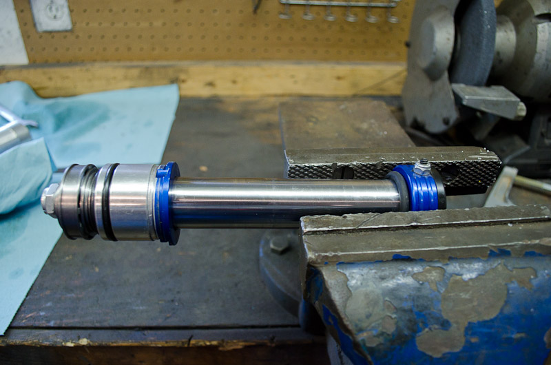
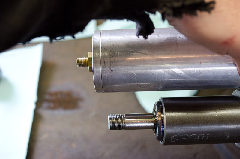
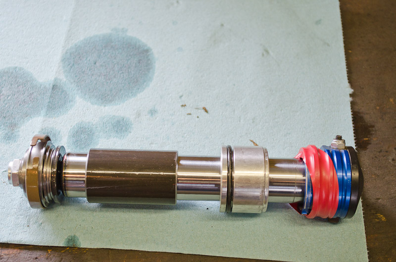
This picture shows what the arrangement would be of a stock 3" bumpstop at full extension. It's hard to hold the ruler with one hand and camera with the other and get an accurate perspective without distortion, but the ruler helps show a good approximation of the lengths (or thicknesses if you prefer) of the different parts. Note the 2-3/8" length spacer and the 3" of shaft available for up-travel. Some dimensions are: - Stock internal spacer: 2-3/8" long (3" bump) / 1-3/8" long (4" bump) |
||||||||||||||
 |
This picture shows what the arrangement would be of a Fox 2.0 series bumpstop with no internal spacer at full extension. The available travel here is about 5-3/8". | ||||||||||||||
What Length?OK, so now we know how to customize a bumpstop, and how it works, the question is - how long should it be (i.e. - how much travel should I shoot for?). Well - the easy answer (easy for me to explain, that is) is to try by trial and error. By having a few different length internal spacers on hand you can easily try 2", 3" and 4" and see what the difference is. The problem is - that's an awful lot of work to pull out, disassemble, modify, reassemble, re-charge, and re-install up to 4 bumpstops every time. And on top of that - yo get the most valid results from this method of "test and tune" you have to run the rig over the same terrain/course at the same speed under the same conditions (like load/weight) every time - otherwise you don't know what the cause of any difference noticed is. Most of us just don't have the time or patience for this - although it works well if you do. Instead, it's nice to have some guidelines or rules of thumb to start with. ASSUMING your suspension is reasonably well tuned beforehand (e.g. assuming it's not to soft and you are trying to use the bumpstop to add some stiffness or roll resistance) and assuming you have a "normal" amount of up-travel or (say up to about 8" or so), then 2-3" of air bump travel seems to be a good range to shoot for. In my experience, no more than about 25% of your shock's up-travel works well as a target. I run about 8" of up-travel front and rear, and initially tried 4" bump in front and a 3" in the rear and the results were TERRIBLE! After some tweaking, I settled on 2" bumpstop travel front and rear. Basically, the length or travel of the bumpstop relates to how soon in the up-travel, and for how long, you need to start slowing down the axle before it reaches the hard stop. Of course, the pressure you charge them too will have a fairly dramatic effect too, and generally the shorter the travel the higher the pressure. Stock pressure is in the 180-200 psi range. The Fox Airshox owner's manual has the following information: "air shocks can be filled with Nitrogen from a range of 10 to 500 psi. To calculate the spring rate, multiply the psi by 1.105 (example 200 psi x 1.105 = 221 lbs/in spring force)" And since the air bump is very much like a short airshock (albeit with different valving and piston, and one end left unattached) I assume that a similar range is possible. However, in practical terms, I would question the need to go less than 50psi or higher than about 400psi. One final note - if you are using coilover shocks with dual-rate springs, you almost certainly want the bumpstop length adjusted so that the bumpstop only comes in AFTER the coilovers have transitioned to the final rate (the rate of the main, or lower, spring). Remember - a bumpstop, even a fancy air bump, is just a bumpstop and is their to help achieve a controlled deceleration of the up-travel and eventual full stop of your suspension up-travel before other suspension or chassis components are damaged when the suspension bottoms out. That said - obviously an air bump is a very tunable device - valving, length, pressure, and theoretically even fluid volume and fluid viscosity - so if you can or want to experiment with all these adjustments to get what you want, more power to you, and don't let anyone tell you you're doing it wrong! ReassemblyReassembly is the reverse of the removal process, with the following notes:
MountingMounting air bumps is fairly easy and straightforward, especially if you use the handy air bump mounting cans sold by Polyperformance and other good vendors. However, there are a few things to keep in mind:
|
|||||||||||||||
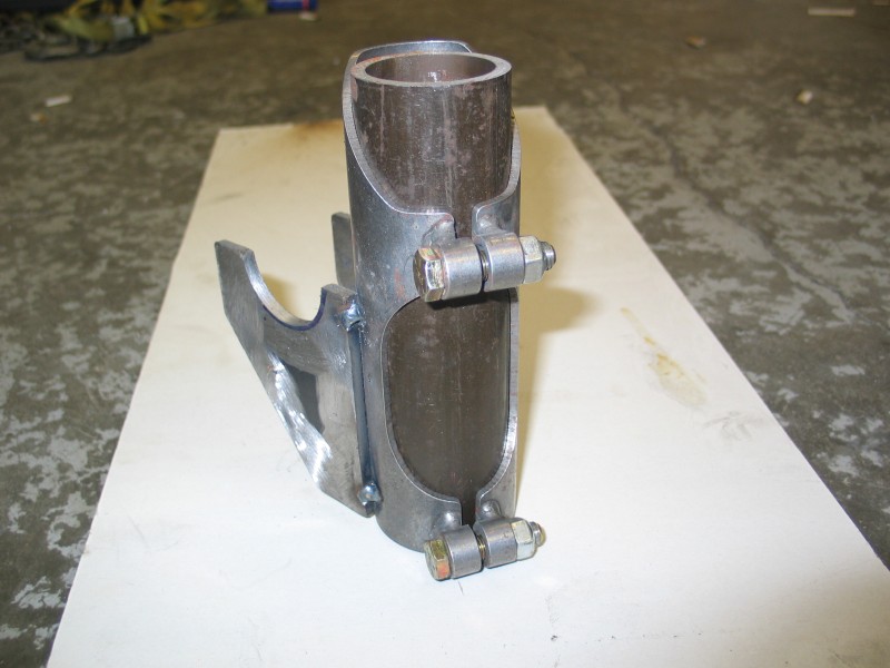 |
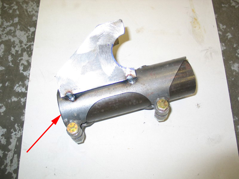
Air bump mounting can from Polyperformance (the tacked-on brackets were added by me) | ||||||||||||||
 |
When welding brackets to the bump mounting can, use a piece of 2" OD tubing in the can to prevent shrinking or warping it with the heat of welding. | ||||||||||||||
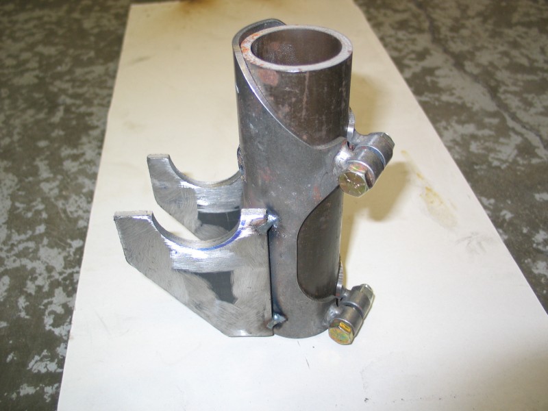 |
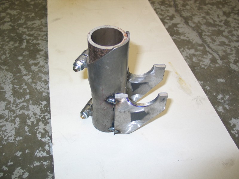
The brackets shown are just the beginning of my mounting - as shown they would probably be insufficient for s sturdy mounting. | ||||||||||||||
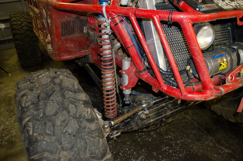 |
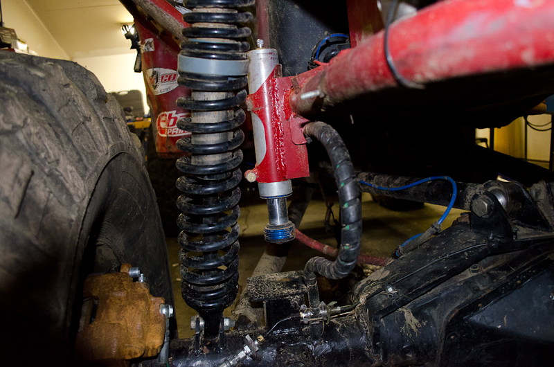
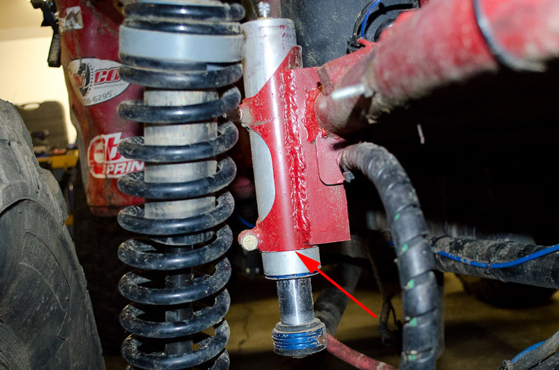
Here's the finished mounting on the front of my buggy. |
||||||||||||||
|
Front bumpstop. Note the travel reduced to 2". | ||||||||||||||
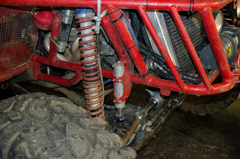 |
Front bumpstop. Note the tube support on top of the bumpstop mounting bracket to distribute force as the front end of the buggy is fairly heavy. | ||||||||||||||
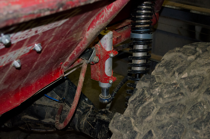 |
Rear bumpstop. Also 2" travel. | ||||||||||||||
 |
Rear bumpstop. Note the size of the contact pad on the axle. | ||||||||||||||
FunctionSo how do they actually function? Well, their purpose is two-fold - first they slow the motion of the axle as it travels upwards, and secondly they provide a "safe" hard-stop to serve as a limit to the uppermost position of the axle relative to the chassis. |
|||||||||||||||
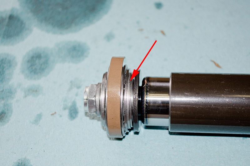 |
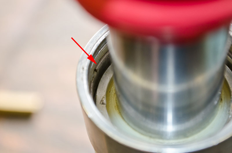
First, as the axle travels upwards and the axle contacts the contact pad the shaft begins to compress. When this happens the piston is forced up through the pressurized fluid, and the fluid is forced through the piston past the compression shims (red arrow at left). This is what slows the axle - technically the kinetic energy of the moving axle is converted to heat via friction as the fluid is forced through the piston and past the shims. In effect, the air bump is damping the axle travel in the same way as a shock does. | ||||||||||||||
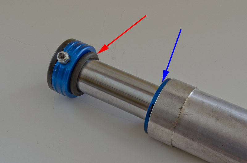 |
Next, when the bump nears the very limit of its travel, the O-ring bumper (red arrow) compresses against the dust cap (blue arrow) providing the last little bit of cushioning before the hard stop. |
||||||||||||||
 |
Incidentally, this shows what the position of the shaft would be inside the body at this point. Obviously there isn't a lot of clearance between the end of the shaft and the inside of the end of the body. |
||||||||||||||
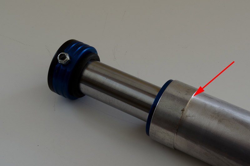 |
The final hard stop is achieved when the bumpstop shaft can travel no further (the head will be hard up against the dust cap with the O-ring bumper being compressed or squished to some degree) and the raised lip on the body (red arrow)... | ||||||||||||||
 |
...is hard up against the bottom edge of the bumpstop mounting can (red arrow)... |
||||||||||||||
 |
... like this. | ||||||||||||||
Advantages & DisadvantagesThere are both advantages and disadvantages to running air bumps, some of which are: Disadvantages:
Advantages
If you're racing (many hundreds or thousands of bumps in a single event), and / or needing to progressively damp and cushion the up-travel of long-travel suspension to a full stop then air bumps are almost a must. If, on the other hand, you spend all day slowly crawling around trails and rocks, then they probably won't do that much for you and simple rubber bumpstop may suffice. If your use falls somewhere in between (e/g/ you like to occasionally rip around over the rough stuff) then you will have to make your own decision based on needs and budget. |
|||||||||||||||
|
|||||||||||||||
|
Sources: PolyPerformance Fox racing Shox (800) FOX-SHOX
|
|