 |
The Coilover Bible - Part 2 By Bill "BillaVista" Ansell |
 |
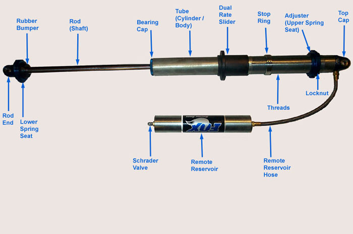
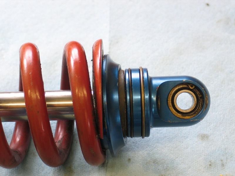
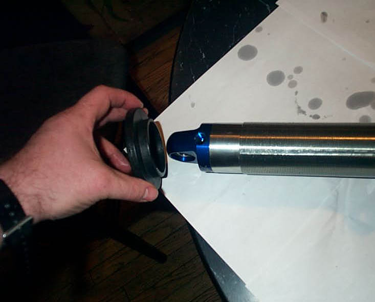
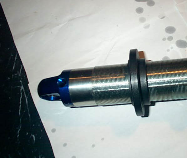
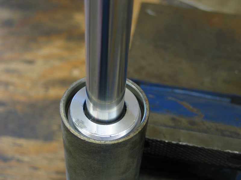
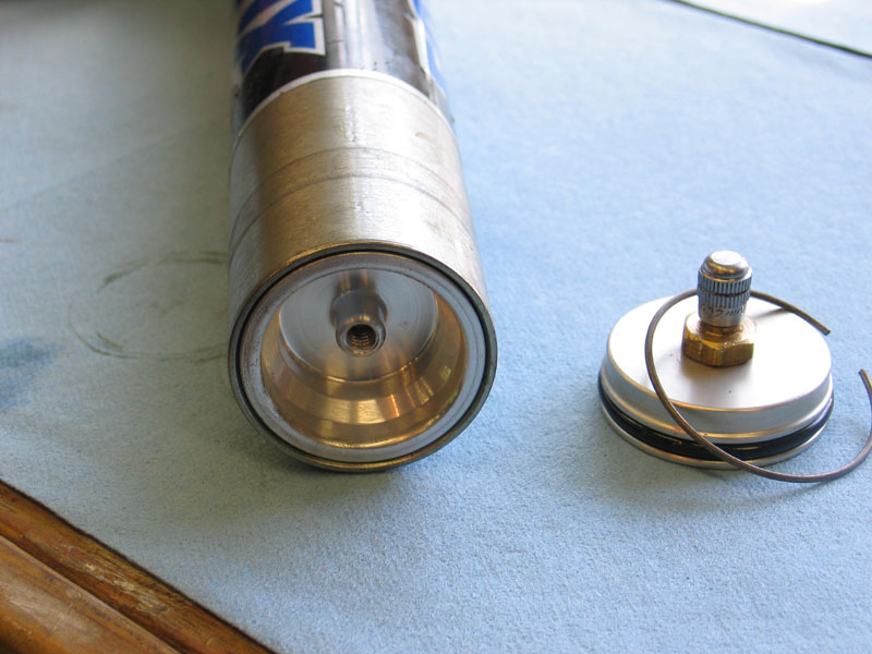
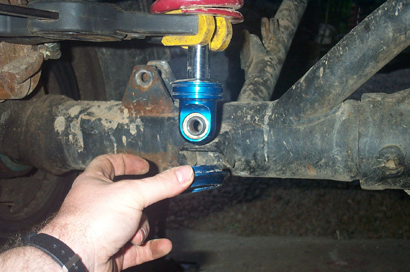
The lower spring seat is held in place with a snap ring. | ||||||||||
 |
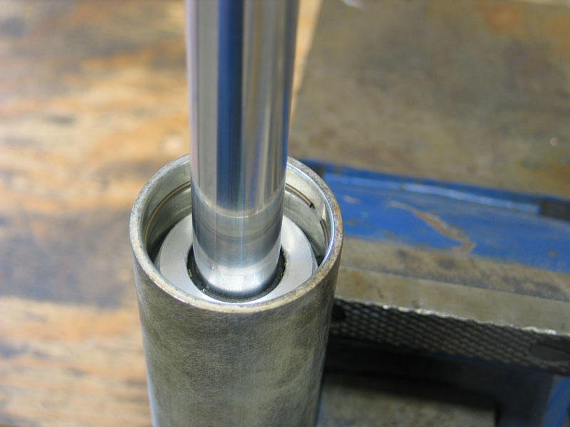
View of lower spring seat dislodged, showing snap ring and O-ring. | ||||||||||
 |
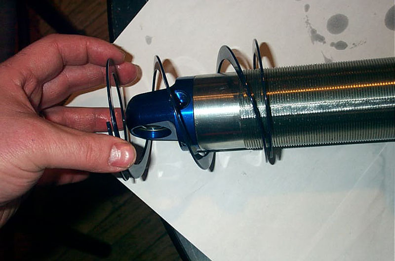
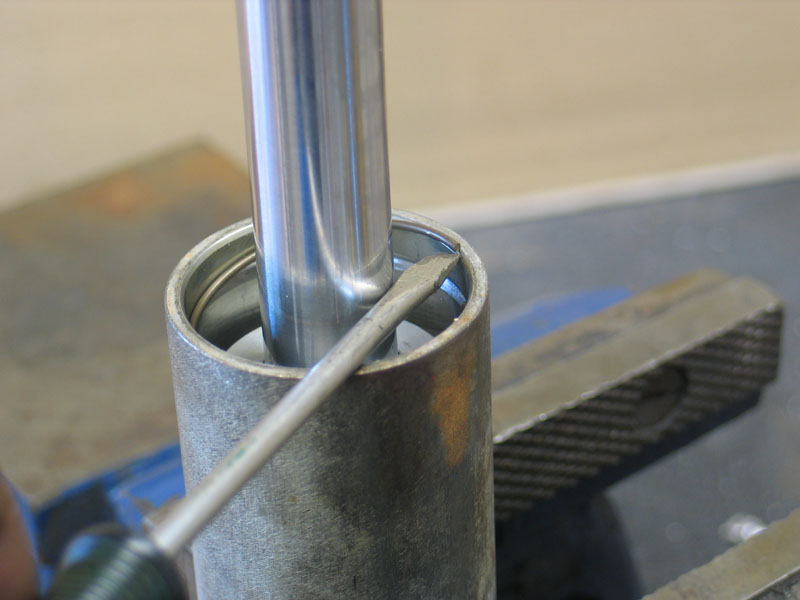
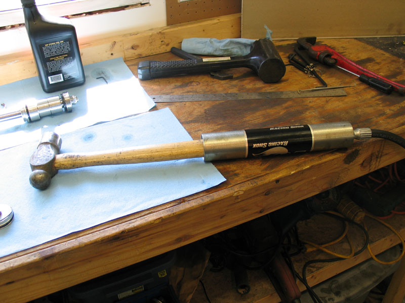
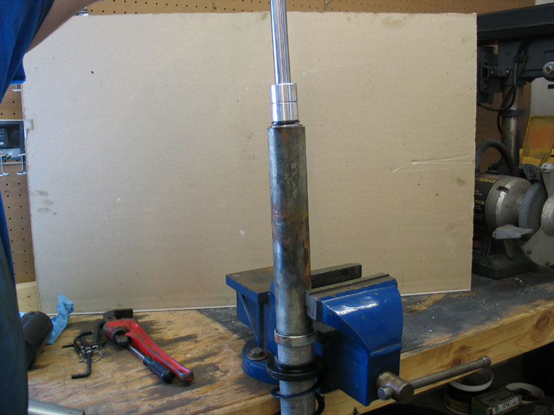
If you're removing springs, working with the shock removed from the vehicle (i.e. with no weight on the springs) before you begin you must relieve any force on the springs. In a triple-rate setup with helper coil you can just slide the springs away from the lower spring seat by hand to remove any pressure on the lower spring seat. In a dual-rate setup you will have to either compress the springs slightly with a coil compressor, or raise the position of the upper spring seat, so that the coils don't apply any pressure to the lower spring seat. Whether installing springs on the shock for the first time or removing springs, begin by tapping the lower spring seat towards the shock tube in order to dislodge it. It helps if the shock is pressurized (which it would normally be) so that the gas charge acting on the rod provides some resistance. |
||||||||||
 |
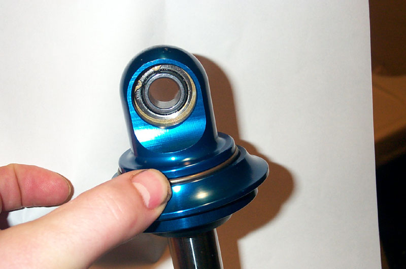
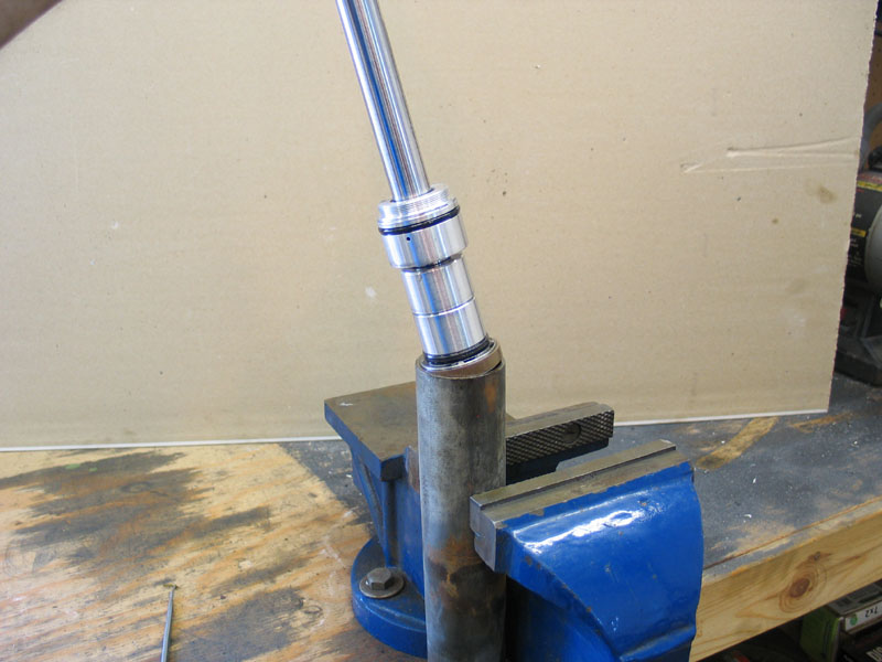
With the spring seat dislodged and moved slightly towards the shock tube, the snap ring and O-ring are accessible. | ||||||||||
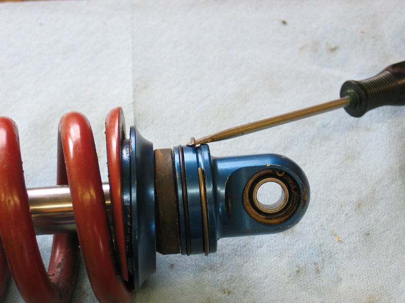 |
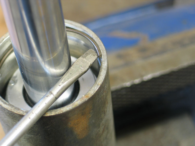
Using a small screwdriver, remove the snap ring and set it aside for re-use. | ||||||||||
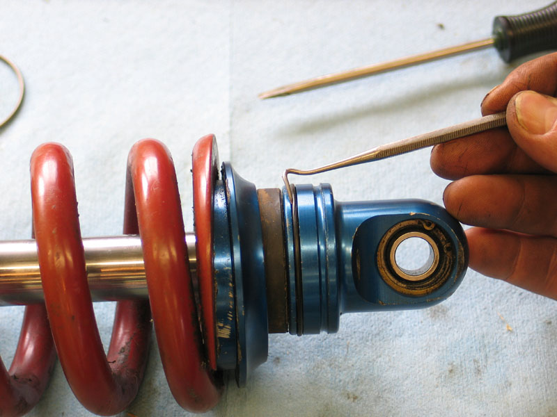 |
Using a pick, and extreme care so as to not nick or cut it, remove the O-ring and set it aside for re-use. | ||||||||||
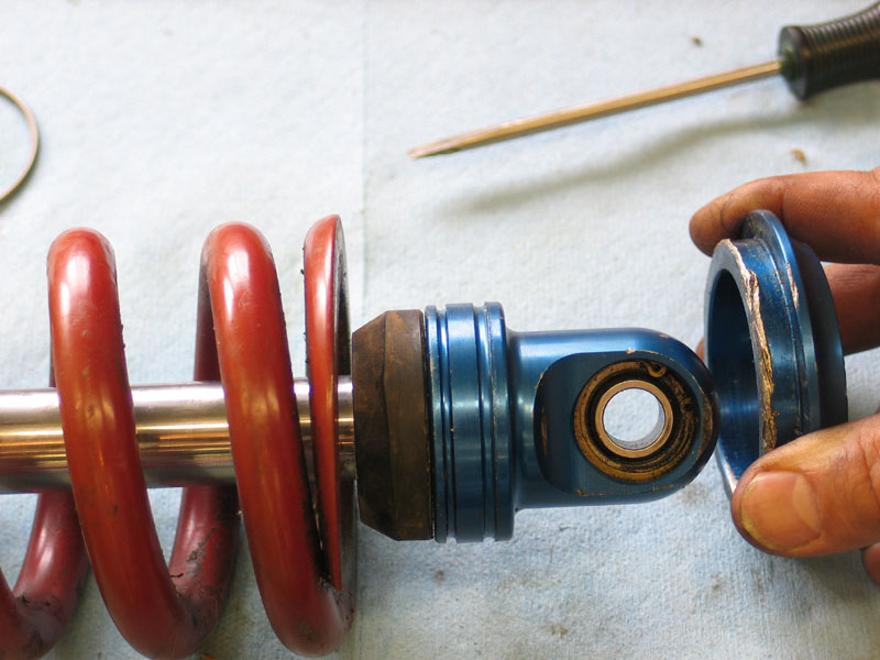 |
With the snap ring and O-ring removed, the lower spring seat can be removed from the shock. | ||||||||||
 |
If required, the springs can now be removed from the shock. | ||||||||||
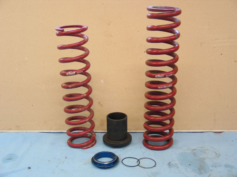 |
To install the springs, gather together:
|
||||||||||
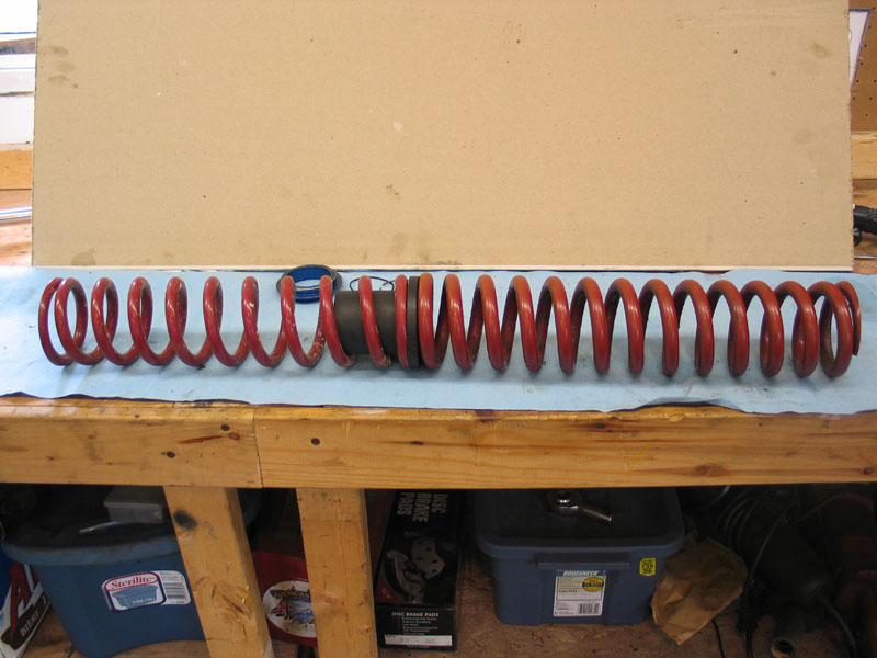 |
Assemble the tender coil, dual-rate slider, and main coil, as shown at left. Ensure the tender coil is on the top, followed by the dual-rate slider with the longer portion inside the tender spring, followed by the main spring on the bottom. The springs should be installed so that the labelling on the spring can be read - i.e. with letter and numbers right-side up. Align the bottom end of the tender coil and the top end of the main coil on the dual-rate slider such that the very ends of the springs are 180 degrees opposite oneanother. This helps the springs sit flat and helps to reduce the amount the dual-rate slider rubs the shock body during spring travel. |
||||||||||
|
Slide the springs and dual-rate slider onto the shock, ensuring the tender spring goes on first and the dual-rate slider is in the proper orientating (with the longer portion of its body inside the tender spring, pointing "up"). | ||||||||||
|
Slide the lower spring seat onto the shock. | ||||||||||
|
Carefully re-install the O-ring, ensuring it is properly seated in its groove and is not twisted or deformed. | ||||||||||
|
Reinstall the snap ring. | ||||||||||
|
Carefully reset the lower spring seat in place. You will feel some resistance at the O-ring. Make sure the spring seat is properly aligned and is square to the shaft, but don't worry if you can't fully seat it on the snap ring with hand pressure alone - it will fully seat once the weight is on the springs. | ||||||||||
 |
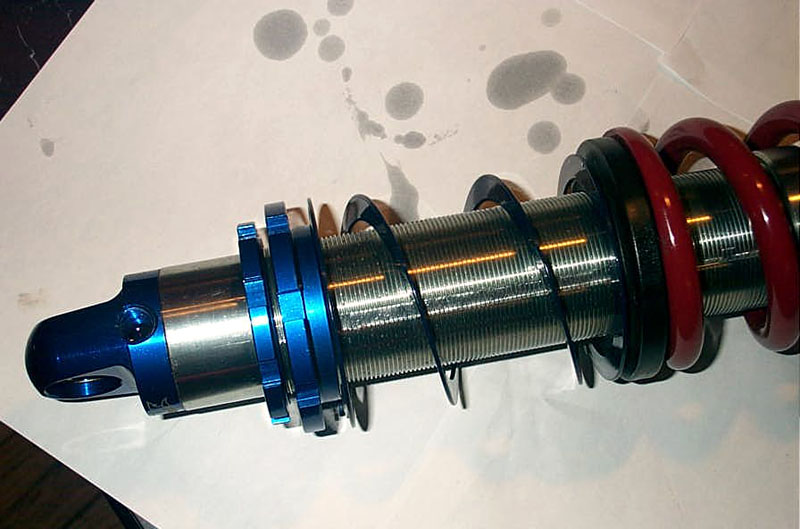
View of completed shock assembly with springs installed. | ||||||||||
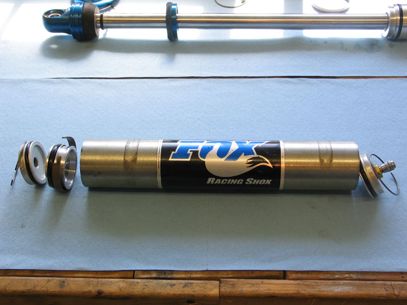
Installing Helper Coil on Fox ShocksInstalling a helper coil on some brands of shock, including Fox, is slightly more complicated. |
|||||||||||
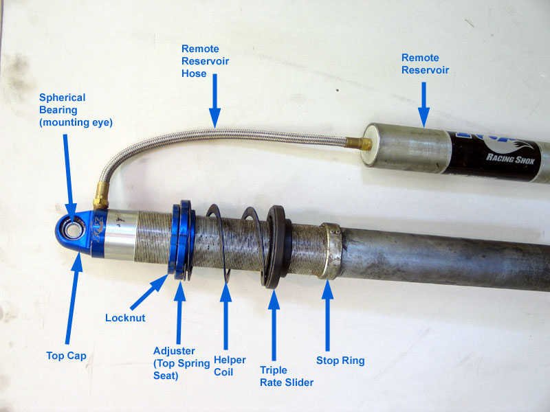 |
This is because the triple-rate slider that fits between the helper coil and the tender coil cannot slide over the stop ring, its inside diameter is too small to allow it to do so. In addition, the stop ring cannot be removed from the lower (rod-end) of the shock, because the threads on the cylinder do not extend all the way down, and the diameter of the cylinder is larger than the minor diameter of the threads. The result is, the triple-rate slider can neither be removed from, nor installed on, the shock from the lower end. It must me installed or removed from the top. This means the remote reservoir hose must be disconnected, and therefore the shock must be bled after the helper coil has been installed. |
||||||||||
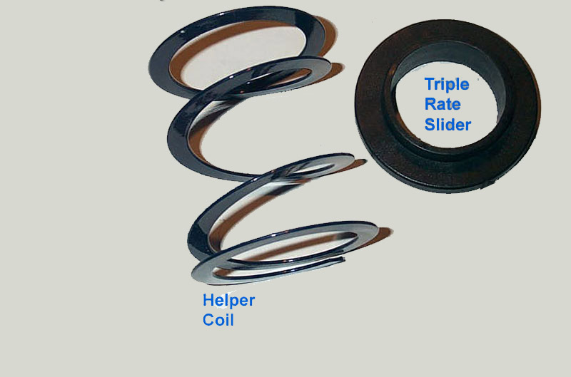 |
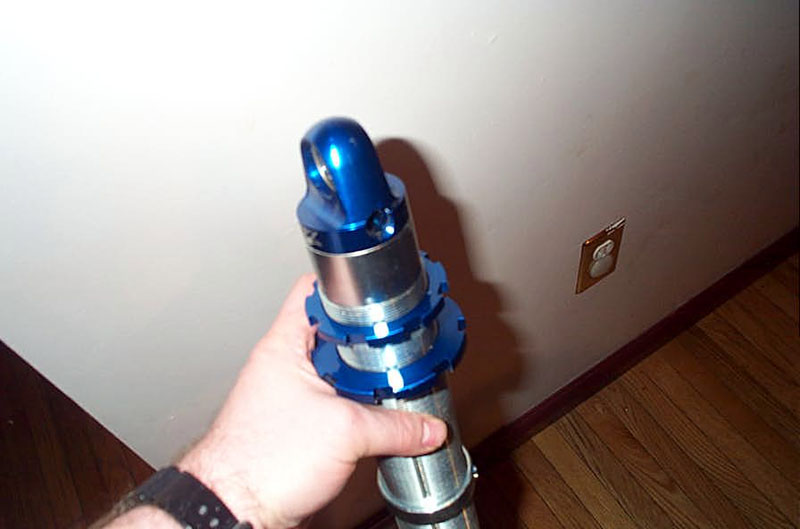
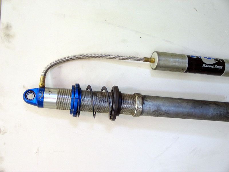
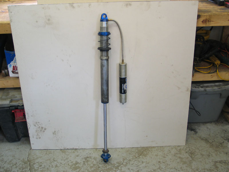
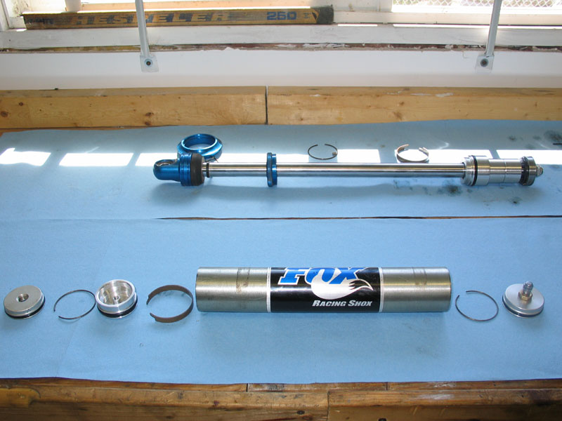
OK, so the object is to get this... | ||||||||||
 |
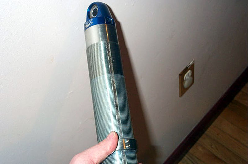
...onto here. | ||||||||||
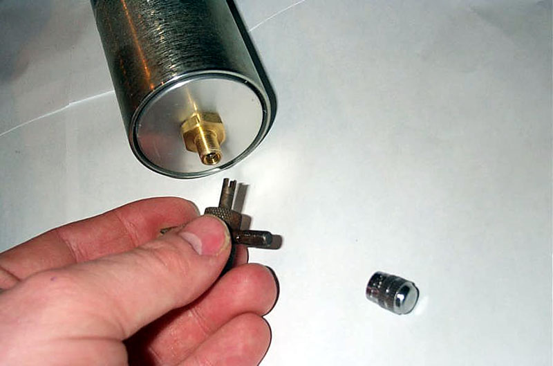 |
You must first completely depressurizing the shock by removing the valve core from the Schrader valve in the remote reservoir. | ||||||||||
 |
Next, carefully remove the remote reservoir hose from the top cap. Be careful not to spill any oil when you do so. | ||||||||||
 |
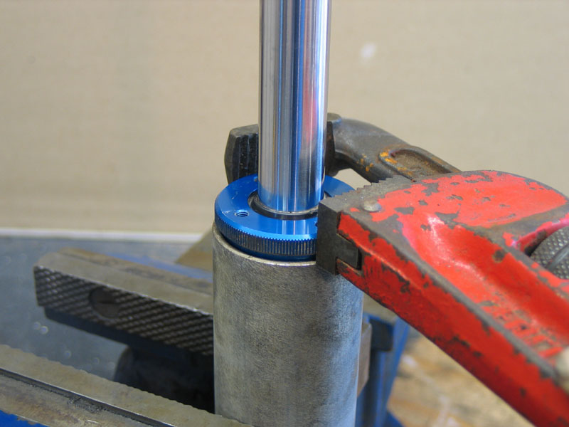
Unscrew the locknut and top spring seat from the cylinder... | ||||||||||
 |
...and remove them completely. | ||||||||||
 |
Install the triple-rate slider over the cylinder with the longer part facing down to go inside the tender coil. | ||||||||||
 |
Triple-rate slider on cylinder. | ||||||||||
 |
Next, install the helper coil on the shock. | ||||||||||
 |
And then re-install the upper spring seat and the locknut. Make sure the spring seat is installed in the right orientation. | ||||||||||
|
Finally, reconnect the remote reservoir hydraulic hose. | ||||||||||
 |
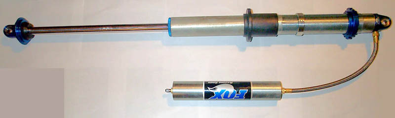
The final assembly should look like this. Before the main and tender coils can be installed and the shock used, however, it must be bled to remove any air that entered when the remote reservoir hose was disconnected. The bleeding procedure is outlined below. |
||||||||||
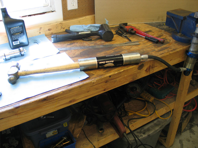
Teardown, Bleeding, & ChargingThis section covers basic disassembly of the shock and remote reservoir. I will structure it as if the intention was merely to bleed the shock of air, and make appropriate notations where required. You can use this same basic procedure to replace a damaged component or even to modify the valving, although I won't be explicitly detailing those steps here. In fact, a detailed look at revalving will be the subject of a later part in the series. Recall from Part 1 of the series that we learned that a shock is really a hydraulic device. Since we will be disassembling this hydraulic device, it is appropriate to remind ourselves of the three cardinal rules regarding servicing hydraulic equipment:
When working on a shock , both the shock itself and the immediate surroundings must be clean. The workshop, work station, tools and clothing must also be as clean as possible. All open parts, hoses, etc. should be plugged or blanked off with, for example, plastic bags, so that dirt and dust cannot enter the system. Despite these precautions, components are never completely clean after being worked on and must therefore always be cleaned immediately prior to installation or reassembly. Brake cleaner is useful for this purpose as it cleans well and evaporates quickly without leaving any residue. So, to disassemble, bleed, and reassemble the shock, proceed as follows: |
|||||||||||
|
Begin by completely depressurizing the shock by removing the valve core from the Schrader valve in the remote reservoir. | ||||||||||
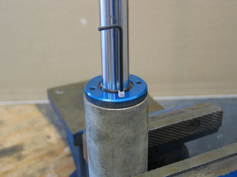 |
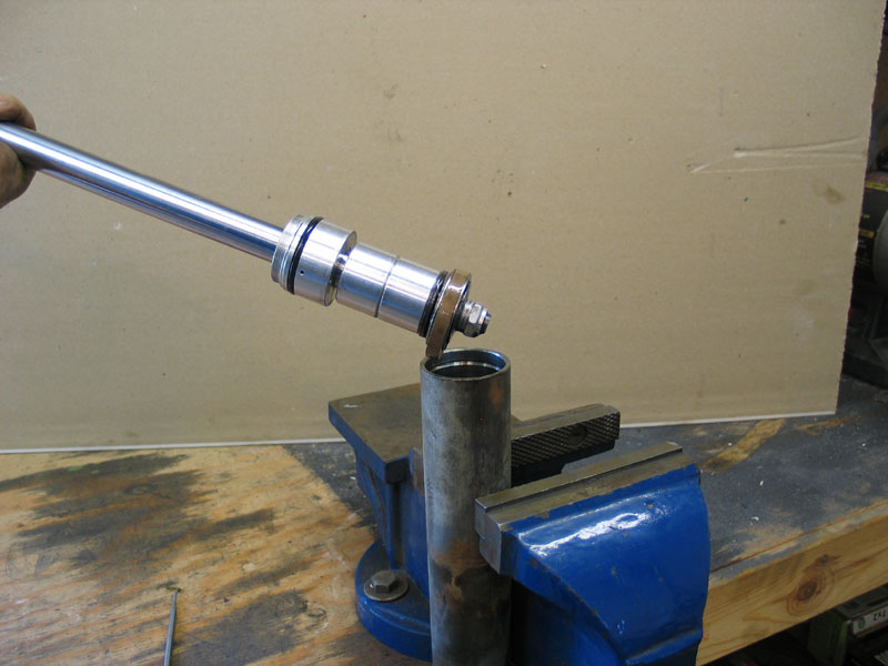
Thoroughly clean the entire shock so that no debris falls inside during the process. Clamp the shock in a vice with the rod-end facing up. It is best to use a vice with soft jaws made from plastic or aluminum or the like. Alternatively, you can place a rag or even a piece of cardboard between the jaws of the vice and the shock body. Remove the Allen-head set-screw from the bearing cap and set it aside. |
||||||||||
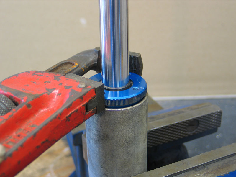 |
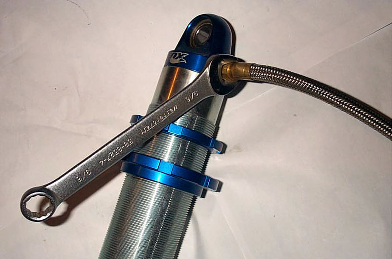
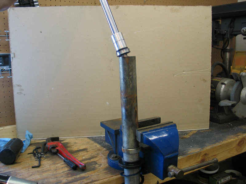
Using an appropriate tool, loosen the bearing cap. Note: This is NOT an appropriate tool - but it was lying around handy! In all seriousness, many of the parts are aluminum and care should be taken not to damage them. |
||||||||||
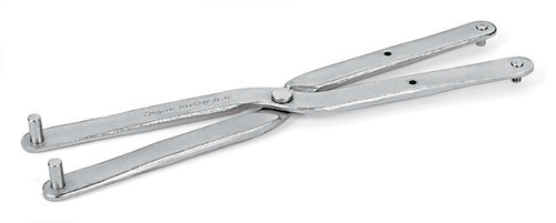 |
The proper tool would be an adjustable spanner wrench whose pins engage the two holes in the bearing cap. The holes are clearly visible in the next pic. | ||||||||||
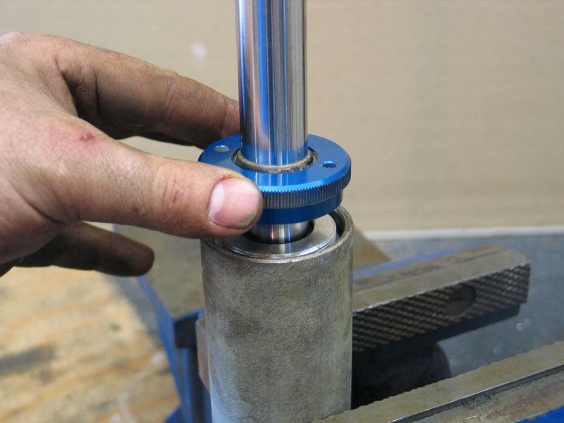 |
Unscrew the bearing cap from the bearing assembly and slide it up the rod. The wiper seal will hold it in place out of the way. The bearing cap is sometimes also known as the "dust cap" or "cylinder end cap". |
||||||||||
 |
With the bearing cap removed, the bearing assembly is accessible. The bearing assembly's purpose is to support the rod and keep the rod and piston aligned with the cylinder. It also contains the primary pressure seal in the form of an O-ring that seals the cylinder. | ||||||||||
 |
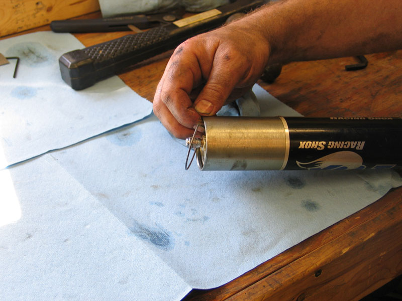
Bring the rod almost to full extension to minimize the chance of oil spillage when you remove it. Push down on the bearing assembly to expose the snap ring. |
||||||||||
 |
Carefully remove the snap ring with a pic or small screwdriver. Use caution not to scratch the cylinder wall. | ||||||||||
 |
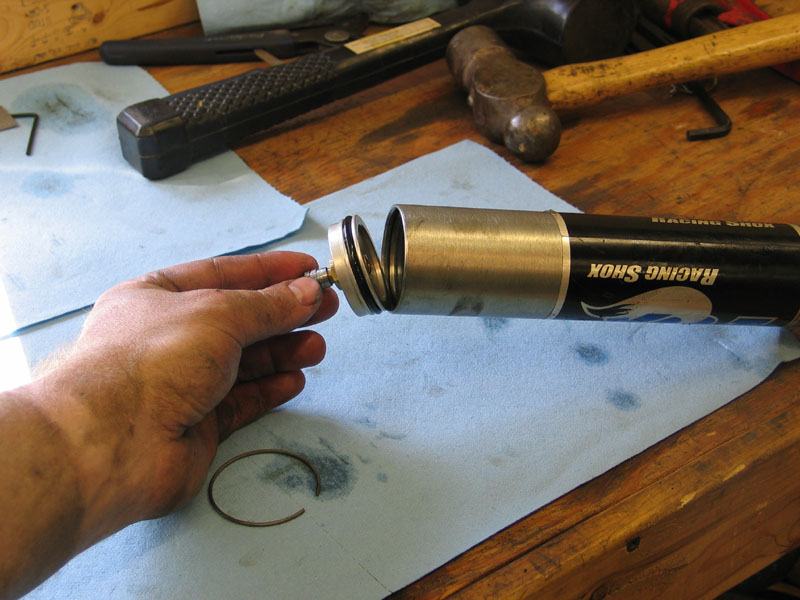
Remove the rod and piston from the cylinder by pulling up on the rod while gently rocking it back and forth and/or rotating it. | ||||||||||
 |
When removing the rod and piston assembly from the cyclinder, exercise caution so as not to dislodge the teflon wear band on the piston such that it falls off into a pile of metal shavings on the floor that you should have swept up yesterday (don't ask!) | ||||||||||
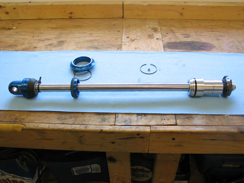 |
Set the rod and piston assembly aside in a clean place. | ||||||||||
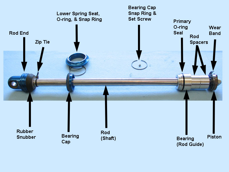 |
Nomenclature of the parts of the rod and piston assembly. The bearing assembly is also sometimes known as the "rod guide", "seal carrier", or "seal head". | ||||||||||
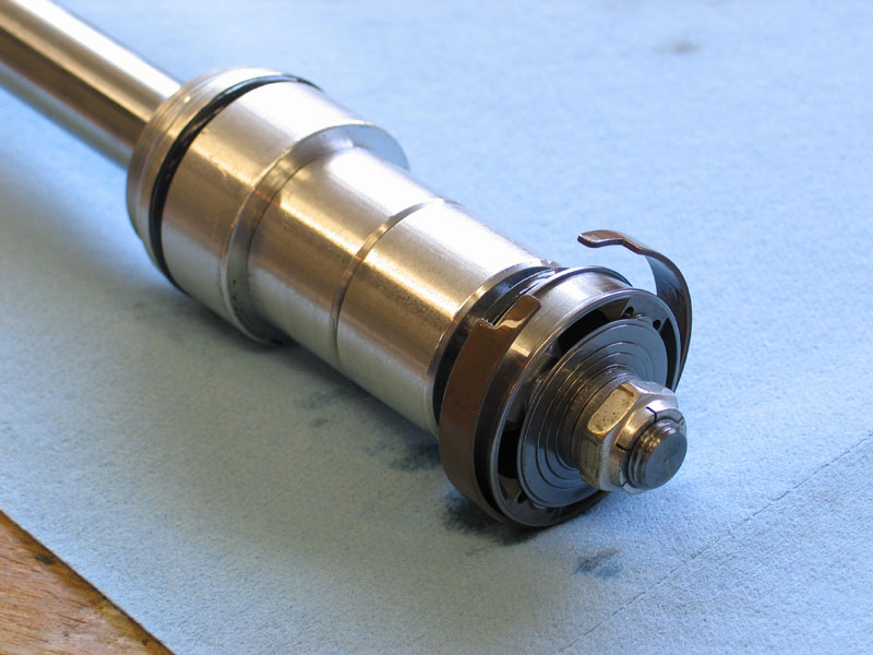 |
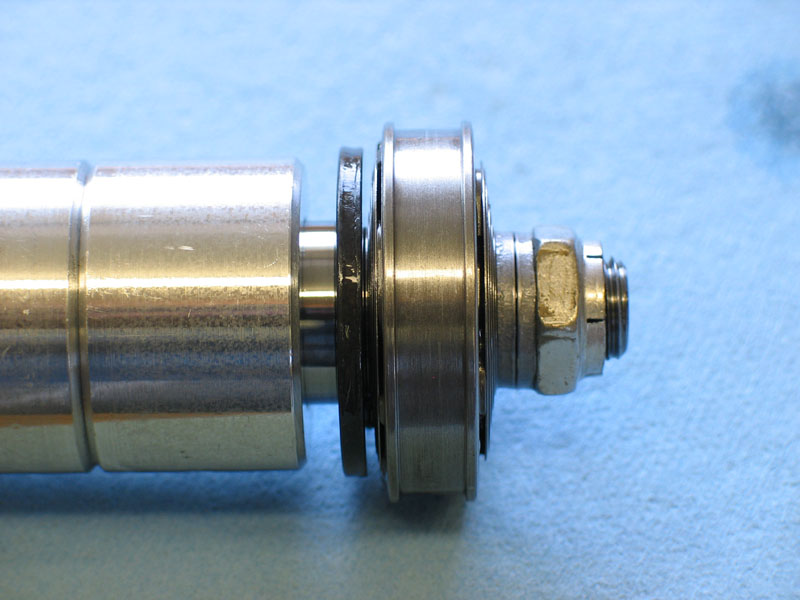
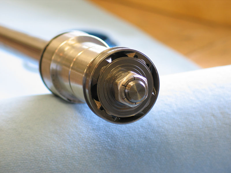
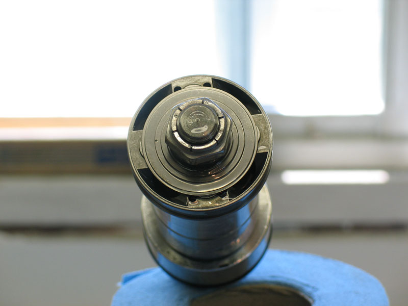
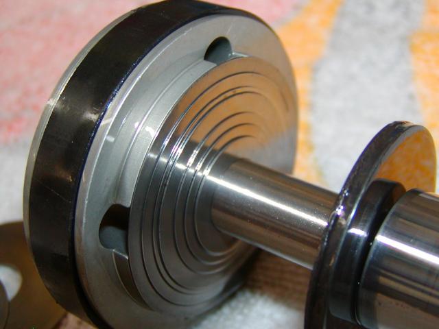
Close-up of the piston-end of the rod and piston assembly. | ||||||||||
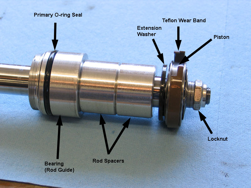 |
Nomenclature of the piston-end of the rod and piston assembly. The rod spacers (aka shaft spacers) serve to limit the extension of the rod which in turn limits the side force on the piston when the shock is at full extension. By preventing the rod from completely extending, they ensure the rod is supported between the bearing assembly and the piston. Without them, the extended shock could easily apply an excessive amount of leverage against the piston, causing damage to the piston from the resulting side load. Do not try to create a longer travel shock by removing the rod spacers - buy a longer shock if required. The black extension-washer located between the piston and rod spacers is also sometimes known as the "extension-stop" or "stop-washer". It is designed to prevent contact between the compression valve stack or piston and the rod spacers. Its purpose is to prevent damage to the valve discs or piston when the shock reaches full extension. |
||||||||||
 |
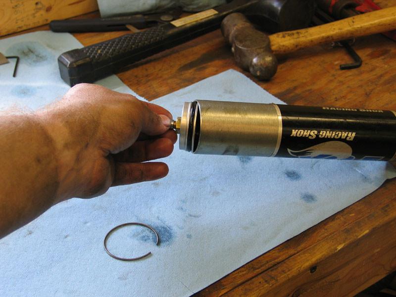
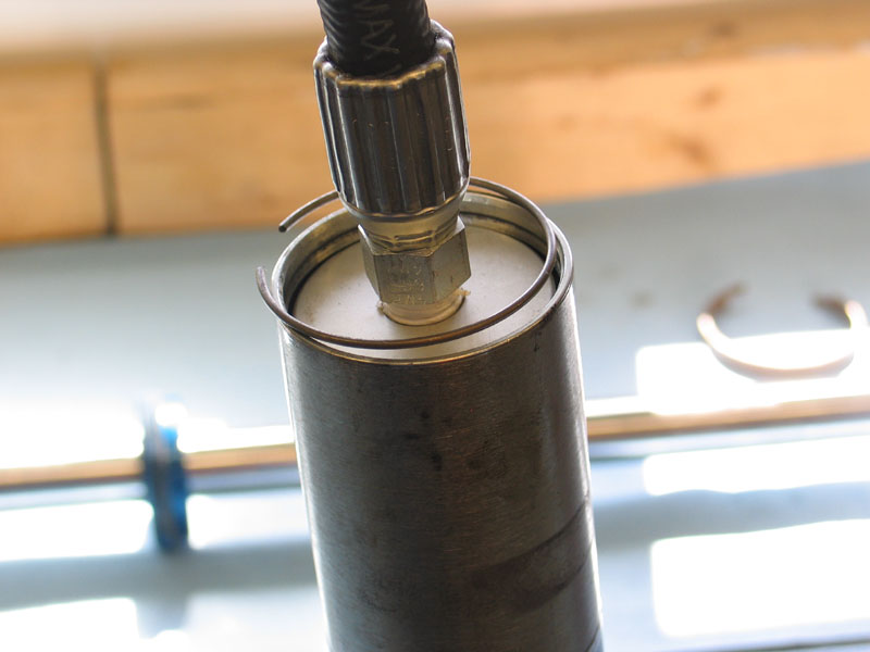
Press down on the remote reservoir end cap, the one with the Schrader valve, until the snap ring is exposed. Remove the snap ring. |
||||||||||
 |
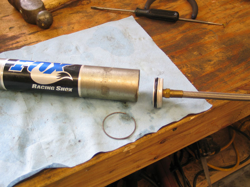
Remove the end cap. | ||||||||||
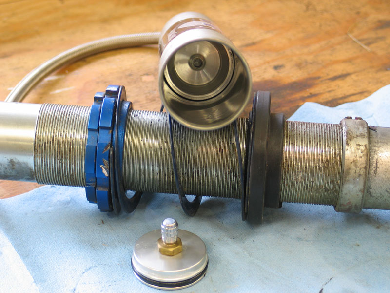 |
You will now be able to see the internal floating piston (IFP) or "divider" in the remote reservoir. There should be no oil visible in the reservoir on this side of the IFP, as this is the gas side that holds the nitrogen charge. If oil is present, you will need to replace the seal on the IFP. |
||||||||||
 |
To begin the bleeding process, orient the shock and reservoir so that the reservoir is below the level of the oil in the shock tube. Using a soft tool (here I am using a hammer handle), set the depth of the IFP by pushing it into the reservoir. Each brand & model of shock will have its own precise specification for the appropriate depth of the IFP in the reservoir. Consult your shocks documentation of contact the manufacturer for the exact number. The exact spec is important as the position of the IFP determines both the amount of oil in the shock and the appropriate volume and pressure of the nitrogen charge. If there is too little oil in the shock the shock can overheat and the IFP and nitrogen charge will not be able to do their job properly, leaving the shock susceptible to cavitation, foaming, and fade. If there is too much oil in the shock, premature seal failure will occur when the oil heats and expands, and in some cases the shock can hydro lock (just like an engine with water in the cylinders), severely damaging the shock. |
||||||||||
 |
I simply marked the hammer handle so that I would know how far I had pushed in the IFP. On a Fox 2.0" series shock, push the IFP approximately 3/4 of the way into the reservoir (8" in for an 11" long reservoir, 6" in for an 8" reservoir). As the reservoir is (or should be) below the oil level in the shock tube, this will also force any air out of the reservoir. |
||||||||||
 |
If you push the IFP too far into the reservoir, you can usually retrieve it by reaching in with some long needle-nose pliers, grasping the centre piece, and pulling it back. Here it is shown having been fully retracted to show the centre piece that you can grab with the pliers. Be careful not to scratch the the reservoir walls with any tools. |
||||||||||
 |
With the IFP at the proper depth, top the shock off with the appropriate oil (in my case, Fox 5wt shock oil) to about 2" from the open end of the tube. Carefully re-insert the rod and piston, making sure the teflon wear band is in place and not lying in a pile of metal filings under the bench (don't ask!) |
||||||||||
 |
To bleed the shock, gently stroke the piston up and down in the tube until no more air bubbles are present. As you stroke, carefully rotate the rod to help dislodge any air bubbles from under the wear band. Proceed with care and patience, as hammering the piston up and down can create more bubbles than it removes. In addition, if you pump the piston too quickly you will force oil through the hose and into the remote reservoir, where, because the reservoir is uncharged, it will move the IFP out of position. If this happens, re-set the position of the IFP and begin again. |
||||||||||
|
Once no more bubbles are present, check and re-set as necessary the position of the IFP in the reservoir. Carefully top off the oil in the tube to within a 1/4" of the open end (don't pour it from a height and aerate the oil as you do so). |
||||||||||
|
Gently lower the bearing assembly into place in the tube. As you do so, any remaining air and a little oil will be forced through the bleed hole in the bearing assembly. You may loose half an ounce of oil or so as you insert the bearing assembly, this is ok. If you're working on a shock without a bleed-hole in the bearing assembly, you can bleed the final bit of air as follows:
Depress the bearing far enough into the tube so that the snap ring can be re-installed. |
||||||||||
 |
Re-install the snap ring, making sure it is fully seated in its groove. This is very important as this snap ring holds the whole shock together. You can easily install the snap ring using just your fingers, but I didn't snap a pic of that so I'm cheating and recycling the disassembly pic from above (Jeez, some of you guys have a sharp eye for details!) |
||||||||||
|
Screw the bearing cap onto the bearing assembly, by hand, until it is snug. | ||||||||||
 |
Lube the reservoir end-cap O-ring with a little oil. Re-install the reservoir end-cap and depress it into the reservoir far enough so that the snap ring can be re-installed. |
||||||||||
|
Re-install the snap ring. Fully compress the shock by pressing down on the rod-end until the piston reaches full travel. This will seat the remote reservoir end cap against its snap ring with a pop or snap sound. If you hear a crackle, it may be Rice Krispies - do not be fooled - check that the end-cap is seated! Before you pressurize the shock, cycle the shock a few times by hand to make sure you have bled all the air out. If there are any air pockets, you will feel them as a sudden drop in resistance as you compress the shock. Also check that the shock compresses fully - if not, it may by hydro locking, indicating that there is too much oil in the shock (i.e. IFP was not at proper depth when shock topped off). If this is the case you will have to disassemble the shock, remove some oil, and begin again. |
||||||||||
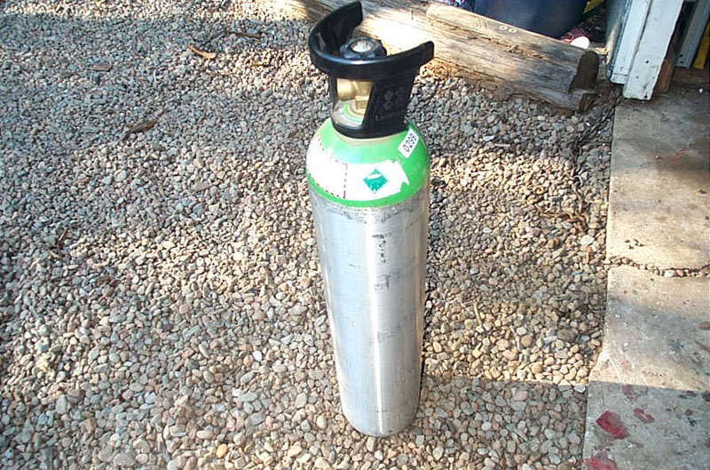 |
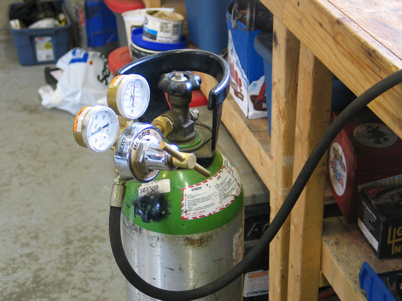
To compete the process, you need to re-charge the reservoir with nitrogen.
You will need a nitrogen tank, like the one pictured at left. They are available from welding gas suppliers. DO NOT use air or CO2 or any other gas. Nitrogen is specifically used due to its thermal stability and the fact that its non-hygroscopic. That means it doesn't contain moisture (water vapour) like air and it doesn't expand and contract with temperature as much as other gasses. This is important because moisture inside the shock can cause corrosion, and excessive expansion of the gas will change the pressure of the gas and therefore alter the shocks performance as it heats up and cools down - which we want to avoid. |
||||||||||
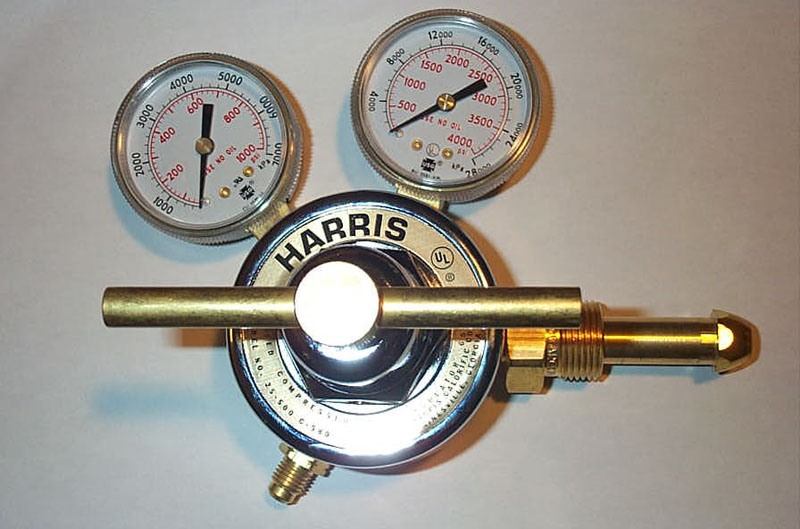 |
You will also need a nitrogen specific regulator, like this one... | ||||||||||
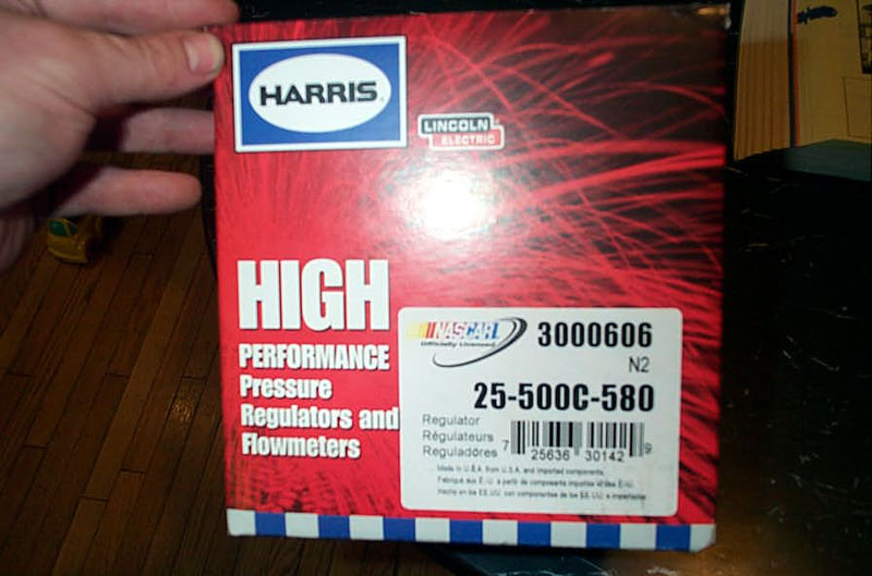 |
...that came in this box. | ||||||||||
 |
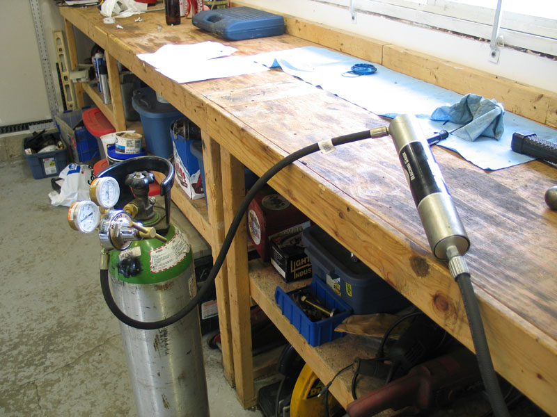
If you're assembling your own nitrogen charging setup, be sure to also use a high-pressure hose and not some flimsy plastic hose, as the pressure in the tank can be upwards of 2000 psi. I used a 2-wire hydraulic hose. Of course, you will use the regulator to adjust the working pressure down and not be blasting the shock, or anything else, with 2000psi nitrogen! |
||||||||||
 |
Charge the remote reservoir to 200 psi. You can vary this pressure + / - 50 psi later, during shock tuning, to make very small changes in effective spring rate, but it is wise to only try this after you have tuned in your spring rates and shock valving. If you do not have the means to charge your own shocks, many ofroad, motorcycle or snowmobile shops can do it for you. Take the shocks to them for this procedure, do not drive the vehicle with uncharged reservoirs. |
||||||||||
 |
Tighten the bearing cap. | ||||||||||
|
Re-install the set screw in the bearing cap and tighten. | ||||||||||
 |
Remove the shock from the vice and cycle the shock a few times to ensure correct and normal function before installing the springs or installing the unit on the vehicle. | ||||||||||
Miscellaneous Pictures of the Inner WorkingsBelow are a few miscellaneous pictures that might help if you are taking your tear-down further than is required for bleeding - for example, if you are changing a seal or O-ring or even modifying the valve stack. |
|||||||||||
 |
To completely disassemble the remote reservoir, the hose side end-cap is removed after the other end-cap, by pressing it down and removing the snap ring. | ||||||||||
 |
Reservoir hose side end-cap removed. | ||||||||||
|
Inside the remote reservoir, showing IFP displaced about 3/4 of the way into the reservoir. | ||||||||||
 |
Completely stripped remote reservoir, showing order of components. Note two snap rings, three O-rings, and the teflon wear-band on the IFP. | ||||||||||
 |
Stripped shock components laid out in order. | ||||||||||
 |
Piston. | ||||||||||
 |
View of the piston and rebound valving discs. | ||||||||||
 |
Another view of the piston and rebound valving discs. | ||||||||||
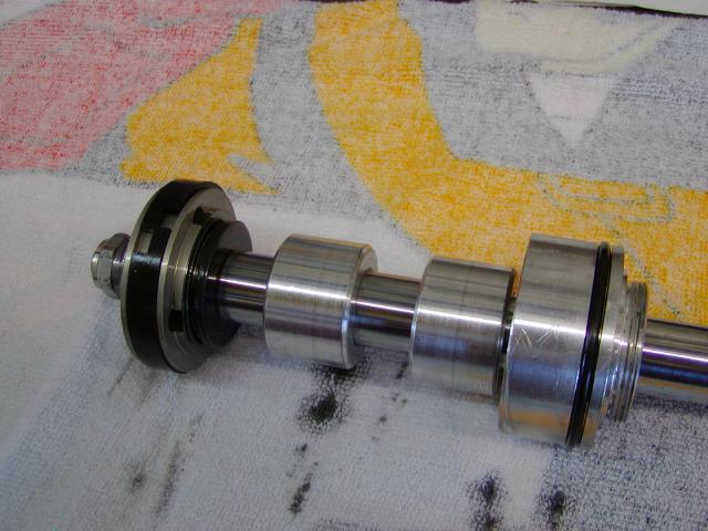 |
Note: The following six pictures, courtesy of Dan Dibble, show a 2.5" shock as opposed to the 2.0" shock illustrated in the rest of the article. From left to right: Locknut, piston & valve stacks, extension-washer, rod spacers, bearing assembly. (photo courtesy of Dan Dibble) |
||||||||||
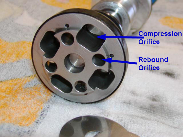 |
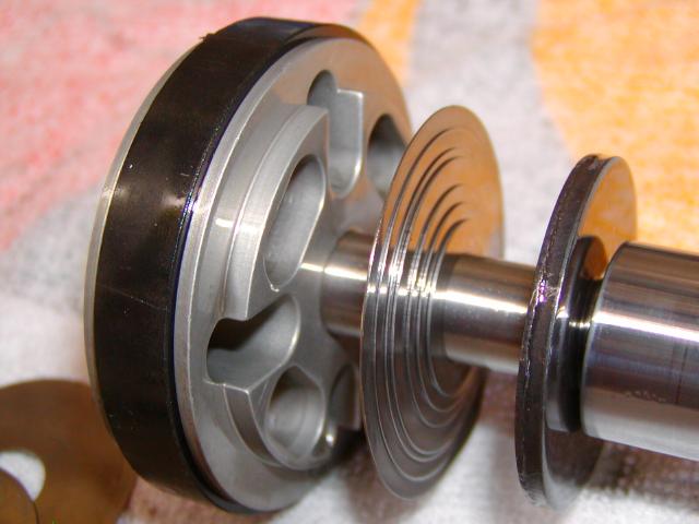
Piston with locknut and rebound valving discs removed, clearly showing the four compression orifices and the four rebound orifices. The larger rectangular-like orifices are for compression damping, the smaller circular orifices are for rebound damping. Typically the compression orifices are larger on most pistons as the compression stroke requires greater flow through the piston. This is because compression velocities can exceed 100 in/s while rebound velocities seldom exceed 25 in/s. If the orifices are too small for the velocity of the piston through the oil, the oil would not be able to flow through the piston fast enough and therefore the piston would experience a huge increase in resistance and provide excessive, unwanted damping. |
||||||||||
You can always distinguish one orifice from another by examining which valving discs completely cover the orifice. The valve discs completely cover their own orifices. This makes sense - if the discs completely covered the opposite orifices there would be no way for the oil to flow and open the valves. So, if you're looking at the free end of the piston (as in this pic) it's the end where the rebound valve discs go, and therefore the orifices that are completely covered by the discs on this end are the rebound orifices. If you're looking at the rod side of the piston, that's where the compression valve discs go and therefore the orifices that are completely covered by the discs on this end are the compression orifices. Another way to say this is: Free side of piston -> rebound discs -> "innermost" orifices are rebound orifices. Rod side of piston -> compression discs -> "innermost" orifices are compression orifices. (photo courtesy of Dan Dibble) |
|||||||||||
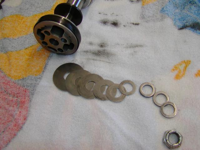 |
Piston with locknut and rebound valving discs removed. The discs, or washers, come in different diameters and thicknesses. A particular combination of discs is called a valve stack or shim stack. As the shock strokes through the oil, depending on the direction of travel, the oil passes throgh the appropriate orifices and then reaches the shim stack. The shim stack must then flex and "open" to allow the oil to pass out the other side of the orifices in the piston. By varying the number, diameter, and thickness of the discs in the shim stack, the pressure at which the stack flexes and opens to allow oil to pass is varied, and thus the shock damping is varied. (photo courtesy of Dan Dibble) |
||||||||||
 |
Compression valving discs in place against back-side of piston. Note the rebound orifices not covered by the compression shim stack. In a Fox shock, a particular shim stack is identified by a number that ranges from 30 to 120, depending on the diameter of the shock. The higher the number, the more damping force the shock will have. For a 2.0" Series Fox shock, both compression and rebound shim stacks are adjustable from 35 to 90 in increments of 5. (photo courtesy of Dan Dibble) |
||||||||||
 |
Compression valving discs and piston. Note the compression valving orifices now visible that are normally completely covered by the compression shim stack. Note: rod side of piston -> compression discs -> innermost orifices are compression orifices. For a 2.5" Series Fox shock, compression is adjustable from 30 to 120 in increments of 5, and rebound is adjustable from 30 to 105 in increments of 5. We shall examine re-valving in detail in a later episode. (photo courtesy of Dan Dibble) |
||||||||||
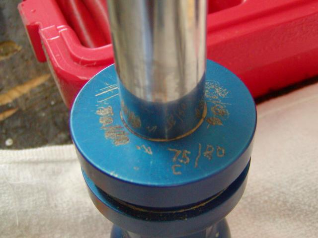 |
In a Fox shock, the damping number is engraved on the rod-end of the shock, just under the rubber snubber. The first number identifies the compression shim stack, the second number the rebound shim stack. Thus 75 / 80 shown in the pic at left, signifies that this shock is currently valved at 75 compression, 80 rebound. The number is a relative number and not a particular unit. Here we can also see that Dan has been busy tuning his shocks and experimenting with different valving, and each time he makes a change he engraves it on the shock. If you have a Fox 2.0 coilover shock and there is nothing engraved on it, the shock has been built with the "standard" 40 / 60 valving. (photo courtesy of Dan Dibble) |
||||||||||
 |
If Fox 5wt oil is not available locally, a quality synthetic shock oil in the appropriate weight can be substituted. These are commonly available from motorcycle shops. Different brands should not be mixed. Mixing and/or substituting different weights is also probably best avoided by all but experienced shock tuners. | ||||||||||
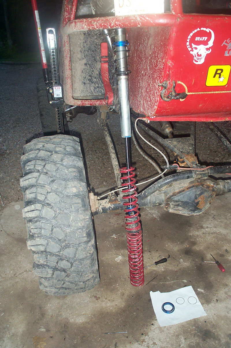
Changing Springs with Shocks Mounted on RigDuring suspension testing and evaluation it is entirely likely that you will, at some point, need to swap springs on the shock. Fortunately the coilover design makes this a simple procedure which can be performed without having to completely remove the shock and remote reservoir from the rig. Here's how: |
|||||||||||
 |
Begin by using a jack to take the sprung weight off the shock. | ||||||||||
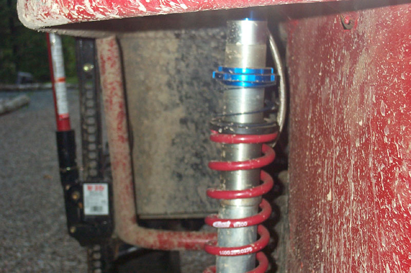 |
You only need to jack the rig up until the tender spring falls away from the top spring seat or the helper coil starts to expand. | ||||||||||
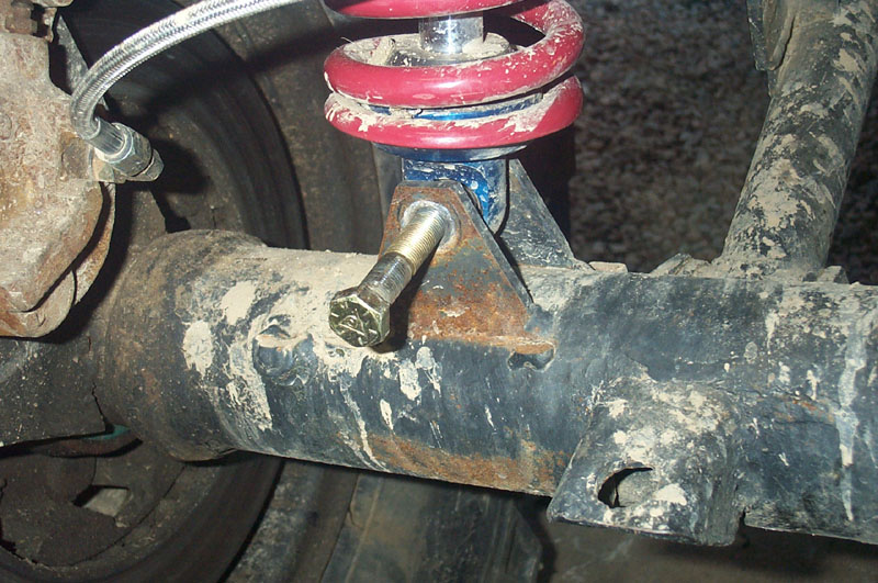 |
With the weight removed, loosen and remove the lower shock mounting bolt. | ||||||||||
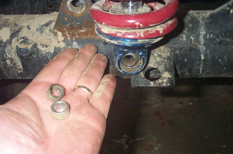 |
Remove the rod-end of the shock from the mounting tabs, being careful to catch and retain the misalignment spacers that fit between the shock's spherical bearing and the mounting tabs. | ||||||||||
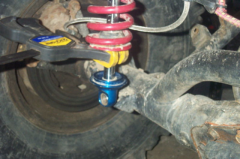 |
To give yourself some room to work, slide the springs towards the top of the shock a little and temporarily retain them there. I found a soft-jawed clamp works well. Do not use any kind of metal clamp on the shock shaft. Alternatively you could tie the springs up. |
||||||||||
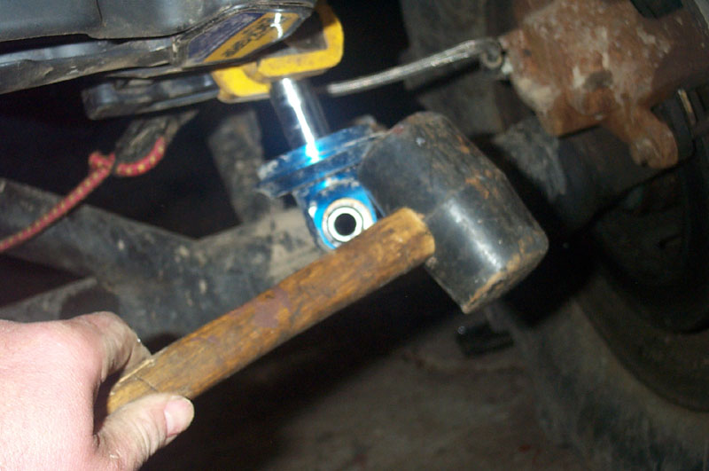 |
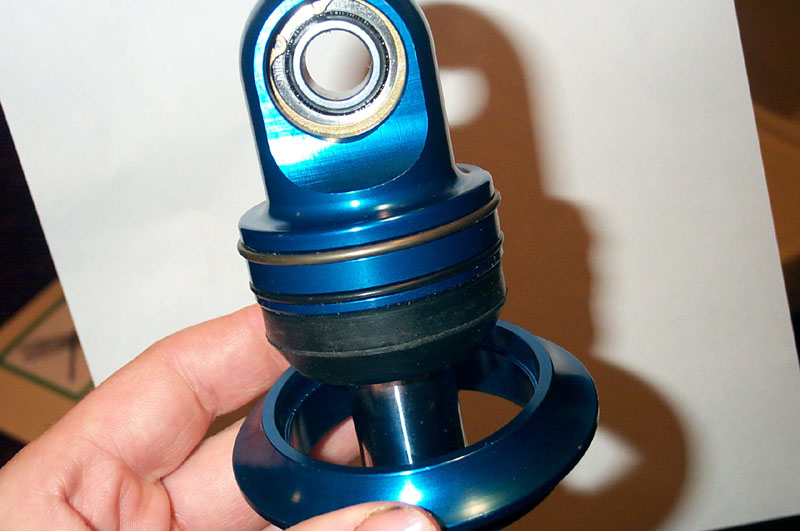
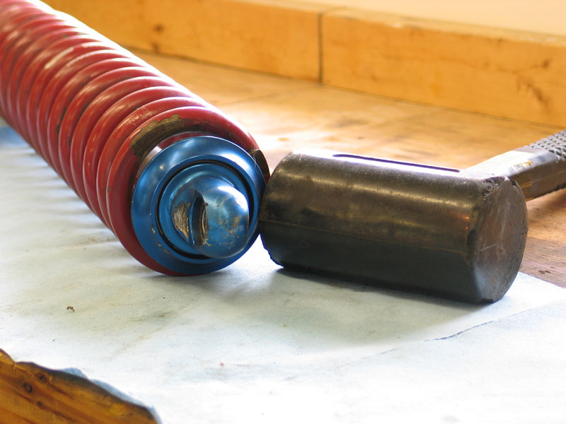
Strike the lower spring seat sharply from below with a soft-faced mallet to dislodge it. Do not hammer the aluminum spring seat with a metal hammer (don't ask!) | ||||||||||
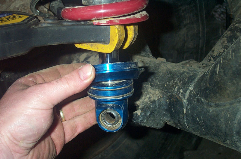 |
Move the lower spring seat up the shaft so that the snap ring can be accessed. | ||||||||||
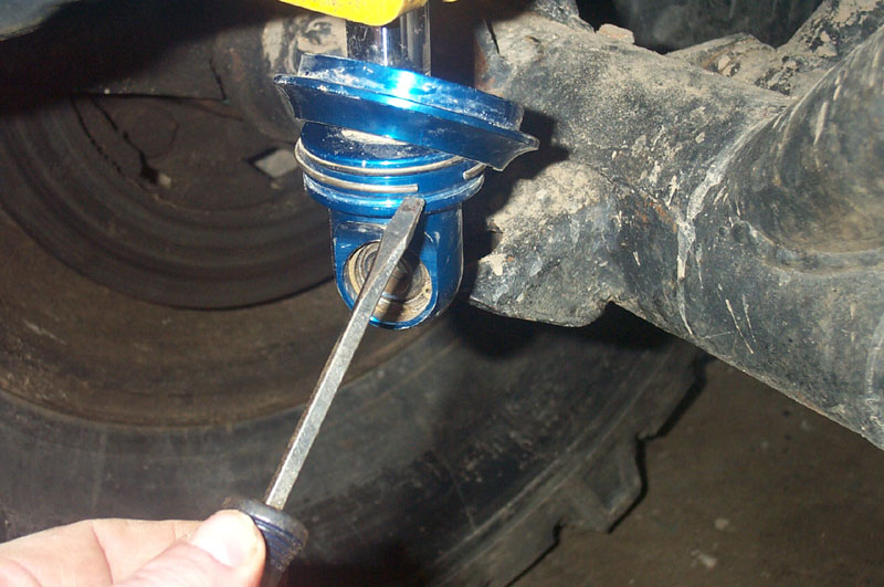 |
Remove the snap ring. | ||||||||||
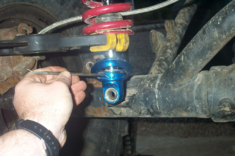 |
Carefully remove the O-ring without cutting or nicking it. | ||||||||||
 |
Slide the lower spring seat off the shock. | ||||||||||
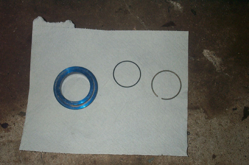 |
Set the spring seat, O-ring, and snap rings aside for reinstallation. | ||||||||||
 |
Carefully remove the clamp, and slide the springs off the shock. | ||||||||||
 |
You may have to angle the shock a bit or compress it to get the springs off. | ||||||||||
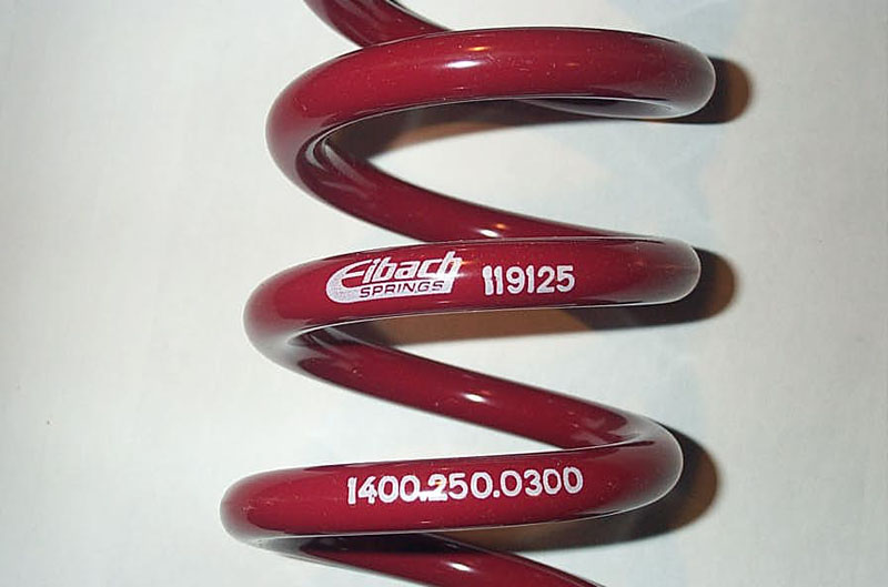 |
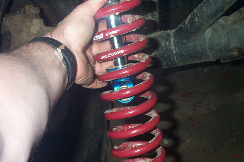
I've used Eibach springs for many years with great success and have always been very impressed with them. In fact, in terms of value and quality I don't think you can buy a better coilover spring. They are also available in a huge variety of rates, diameters, and lengths - as far as I know more than any other brand. All of which are listed, along with all the other necessary specs, in the excellent Eibach Racing Springs Catalogue. They have a simple and very useful 11 digit part-numbering scheme that is clearly marked on the spring. |
||||||||||
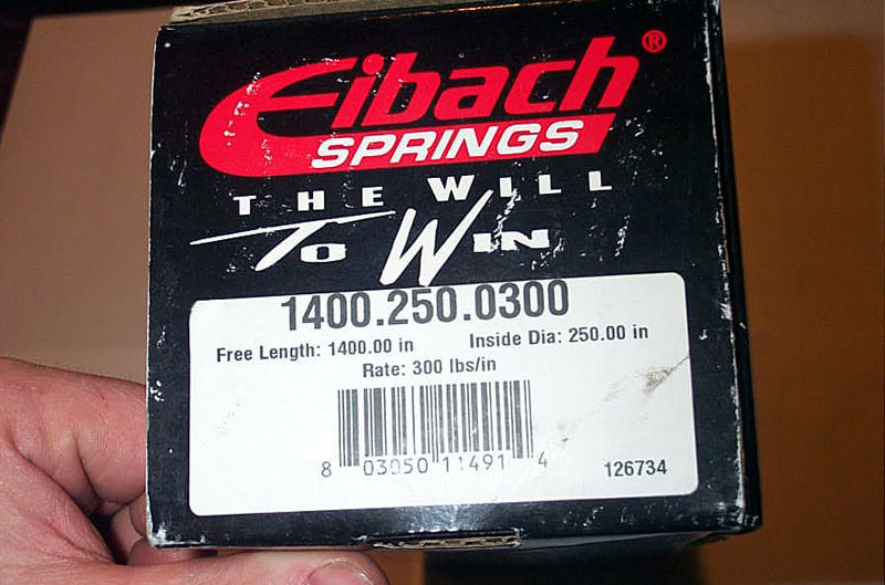 |
The part number is also marked on the box in which each spring comes. The decode is as follows:
This spring in this box is a 14" long, 2.5" ID, 300 lbs/in coilover coil spring. (if you enlarge the photo at left, you will see there's a typo on the box where the fine print actually states that the spring is 1400.00 inches long - but that's silly - it's almost 39 yards - it wouldn't fit in the box!) |
||||||||||
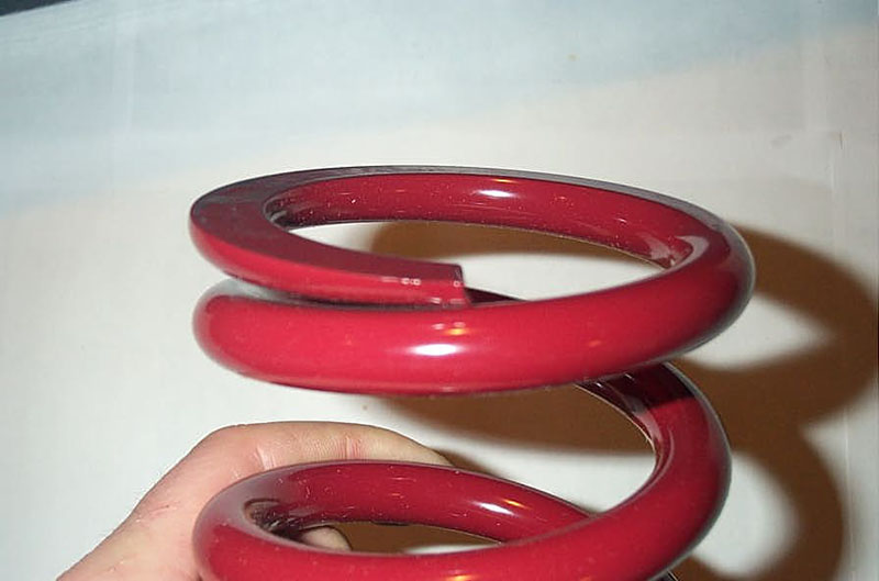 |
Both ends of the coil are flat, to properly seat against the spring seats and dual-rate slider. | ||||||||||
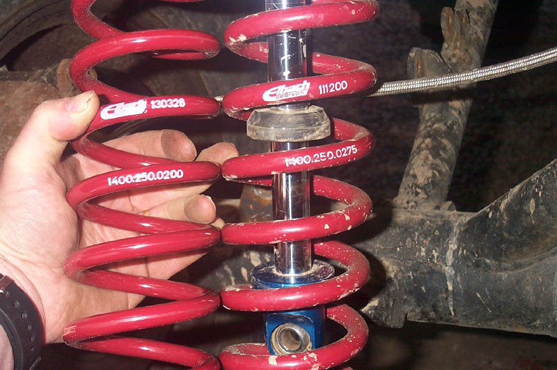 |
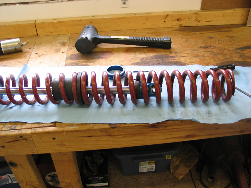
Here I am swapping a 14" 275 lb tender coil for a lighter, 14" 200 lb coil on the rear of my buggy. Note the difference in wire diameter between the springs. | ||||||||||
|
When installing the new springs on the shock, make sure to do so in the correct order, with the springs and dual-rate slider the right way up. The springs should be installed so that the labelling on the spring can be read - i.e. with letter and numbers right-side up. The DRS should be installed with the longer part up. The tender (top) coil goes on first, followed by the DRS, and then the main (lower) coil. Align the bottom end of the tender coil and the top end of the main coil on the dual-rate slider such that the very ends of the springs are 180 degrees opposite oneanother. This helps the springs sit flat and helps to reduce the amount the dual-rate slider rubs the shock body during spring travel. |
||||||||||
|
With the new springs in place on the shock, once again clamp or tie them out of the way, so that you can re-install the spring seat, O-ring, and snap ring by reversing the removal process. | ||||||||||
|
With the shock and springs re-assembled, we come to the worst part of the procedure - fishing the little misalignment spacers back either side of the the rod-end and between the shock mounting tabs, while keeping them aligned with the holes in the spherical bearing and the mounting tabs. An extra pair of hands, or patience, is extremely helpful. If you find yourself working with neither, as I frequently do, I have found that beer helps. What I wouldn't give for a shock with spherical bearings with integrated misalignment spacers...or more beer! |
||||||||||
|
Once you do get the little devils in place and lined up, reinsert the mounting bolt and torque to spec with a locking nut or thread locker. Repeat as necessary to get the perfect balance of ride and handling. |
||||||||||
|
|||||||||||


|