 |
Dana 60 Big 35 Spline Axle Upgrade By Bill "BillaVista" Ansell |
IntroductionThe venerable Dana 60 front axle is a seriously beefy piece of kit for the hardcore wheeler. But like so many things, everything is not always what it seems, and everything has its weak points. This article is dedicated to illuminating, then eliminating the weak points of a stock Chevy Dana 60 front axle. For the purposes of this article, Dodge kingpin Dana 60 front axles will be identical. I should make a small note here about my philosophy, as it will help to illuminate some of the points I will make. In building a rig, I do not believe in designing in a "weak link". It just makes no sense to me - not when I intend to fully explore the limits of man and machine when I go wheeling. What I want to be the "limit" is not a weak part, but rather the limit of traction (i.e. tires break free before anything breaks) or my courage / sense (I let off the throttle and/or try a different line before anything breaks). |
 |
Of course, this may not be achievable - anything CAN break - but that is my philosophy. I want everything to be as strong as possible (within my economic realities) and in a reasonably balanced system (no point running 60 outers on a D30 front!). I find this to be particularly important when building an axle, as there are no really simple / cheap "fuses" to build in. If a U-joint breaks, it often destroys the shafts with it (or vice-versa) ; if a stub shaft goes, it often takes out the hub (lockout) and it can ruin/deform the spindle. In other words - breaking sucks. I want to build to wheel - not build to break. So, what are the weak points of the Dana 60 front? The areas needing upgrading are: Early "neck-down" inner 35 spline shafts - (breaking can shock-load and damage locker and/or opposite side axle) Stock 30 spline stub shafts - (breaking usually destroys lockout, and can ruin the spindle) Stock 30 spline lockout hubs Stock 1480 series U-joint - (breaking usually deforms the ears on both inner and stub shafts) 35 Spline lockout hub. The 1980 Chevy K30 1 ton 4x4 front dana 60 in my Wolf suffered from most of these weaknesses. I am presently running 39" Michelin military tires on some pretty rough terrain, and I plan on running 42" tires soon, so some beefing was in order. I called up Greg at 4WDFACTORY.com. He is the man when it comes to Dana 60 parts and upgrades, and carries every part you might need to rebuild or upgrade your Dana 60. I settled on a complete 35 spline stub axle package with drive flanges, new "big" 1.5" 35 spline inner axles and a pair of kingpin rebuild kits. The kingpin rebuild I cover in a separate article you can read here. This article covers all the rest, in 5 parts: Part 1 - Kit Contents |
|
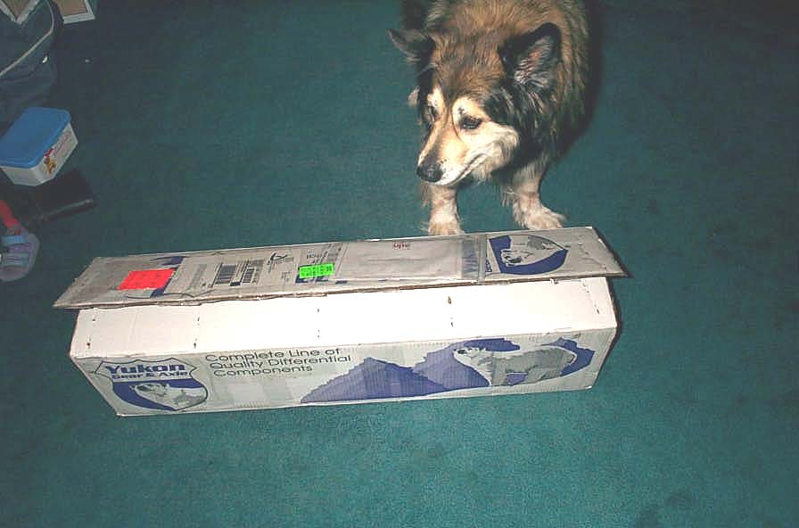 |
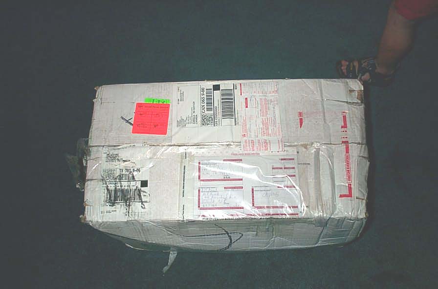
All of the gear I ordered arrived in 2 large, heavy, well packaged boxes. Step one was to have "Bear" give it the old once-over to make sure everything looked good. She gave an enthusiastic "paws-up". | ||||||||||||||||||||||||||||||||||||||||||
 |
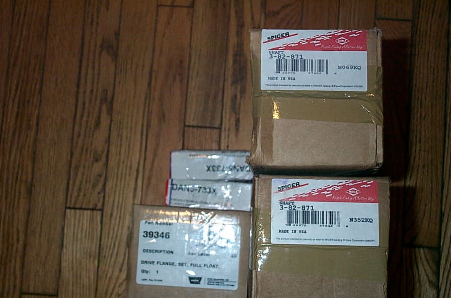
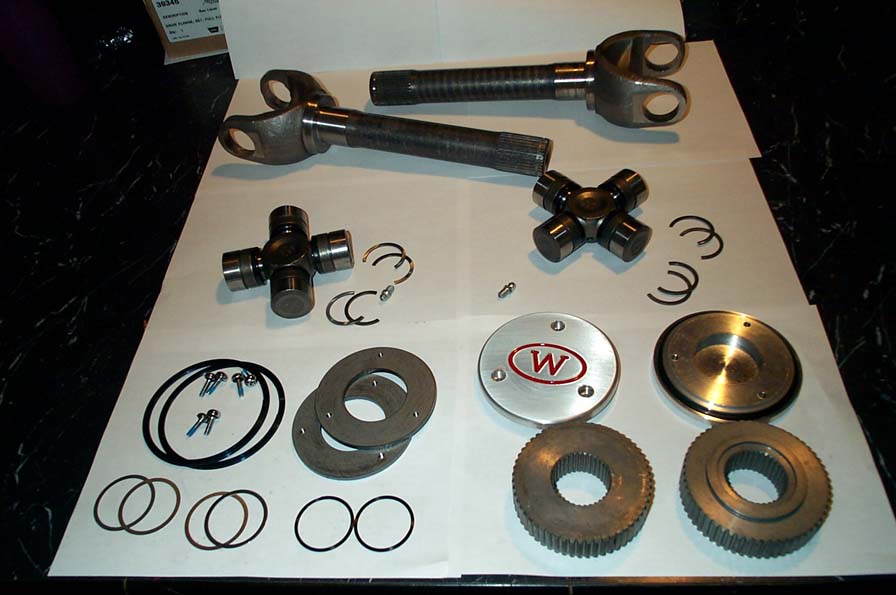
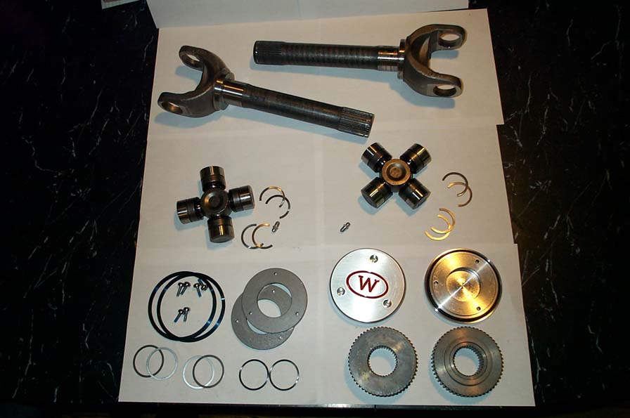
This box contained the stub axles, U-joints, Warn 35 spline drive flange kit, kingpin rebuild kits, stickers, and a Yukon catalogue. | ||||||||||||||||||||||||||||||||||||||||||
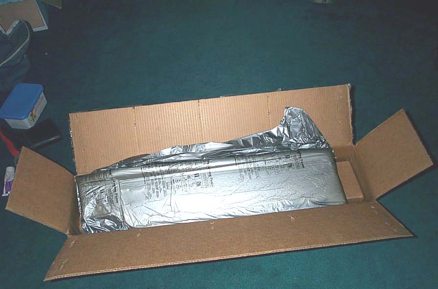 |
This box contained the inner axle shafts. The shafts were wrapped in anti-corrosion paper, placed inside boxes, those boxes were surrounded by packing foam, and placed inside another box. Everything arrived in flawless condition - no shipping damage at all - and that's all the way from Texas to Nova Scotia! I've said it before many times - but I'm such a fan of well packaged goods. | ||||||||||||||||||||||||||||||||||||||||||
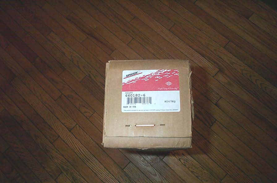 |
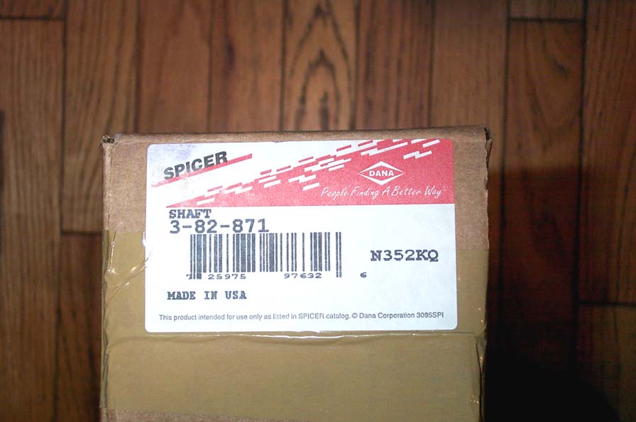
Actually, the parts themselves came inside Dana/Spicer boxes that were inside the Yukon boxes. This box contains the long-side inner shaft. | ||||||||||||||||||||||||||||||||||||||||||
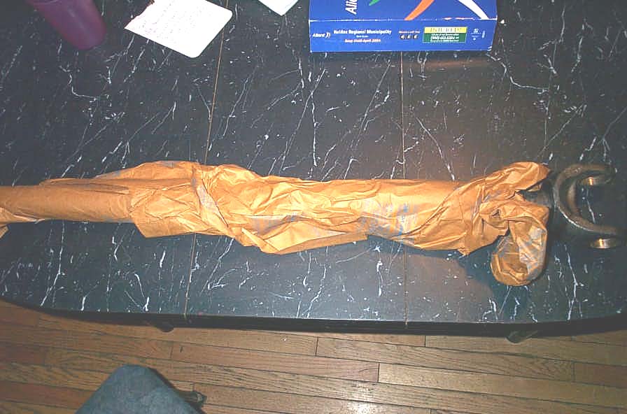 |
This is the long-side inner shaft wrapped in its protective paper. It's also lying on the kitchen table - I have such a wonderful, understanding wife! | ||||||||||||||||||||||||||||||||||||||||||
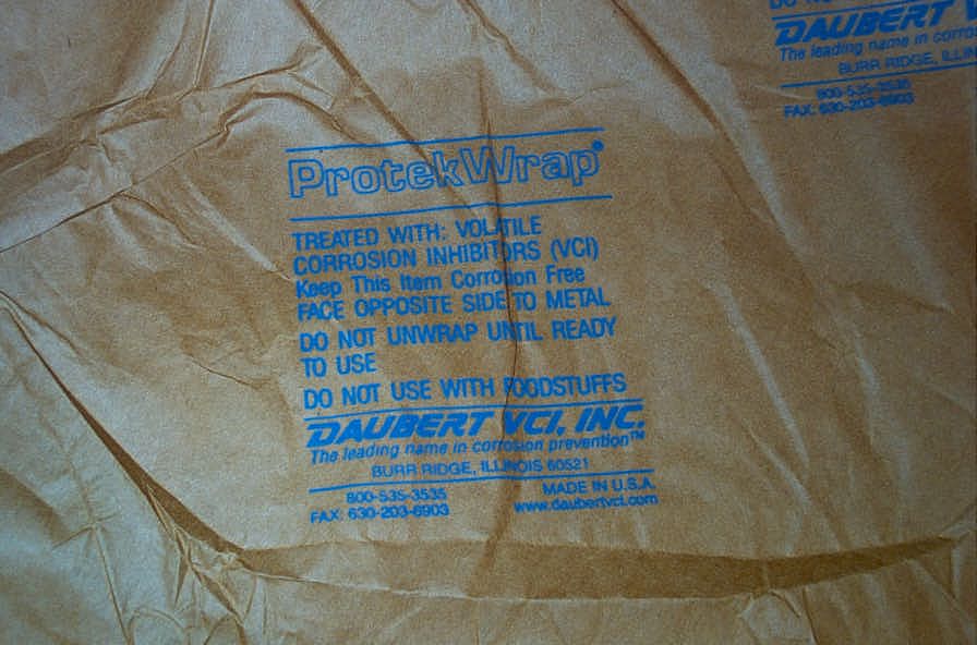 |
The wrapping is called ProtekWrap and contains Volatile Corrosion Inhibitors... | ||||||||||||||||||||||||||||||||||||||||||
 |
...whatever that means - it works, there wasn't a spot of rust on the shafts, despite the raw machined steel. | ||||||||||||||||||||||||||||||||||||||||||
 |
Here's the contents of the 35 Spline upgrade "kit":
|
||||||||||||||||||||||||||||||||||||||||||
 |
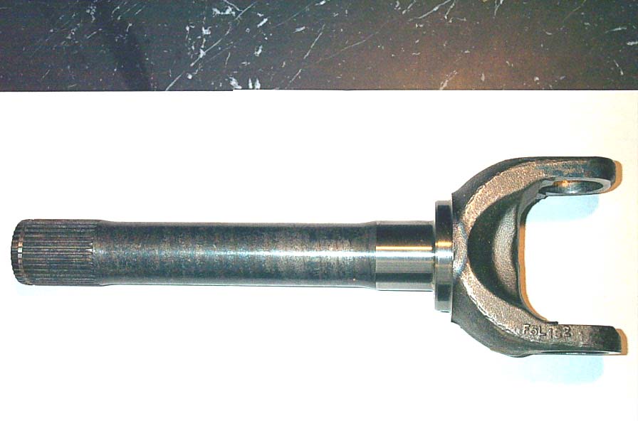
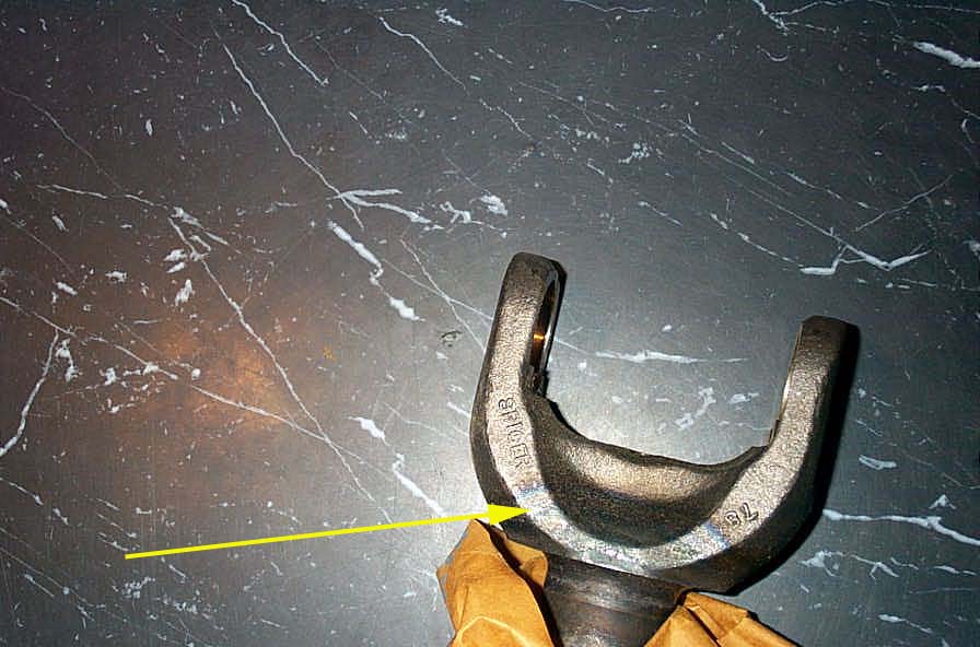
35 Spline stub shafts (D70) Spicer part #: 3-82-871 | ||||||||||||||||||||||||||||||||||||||||||
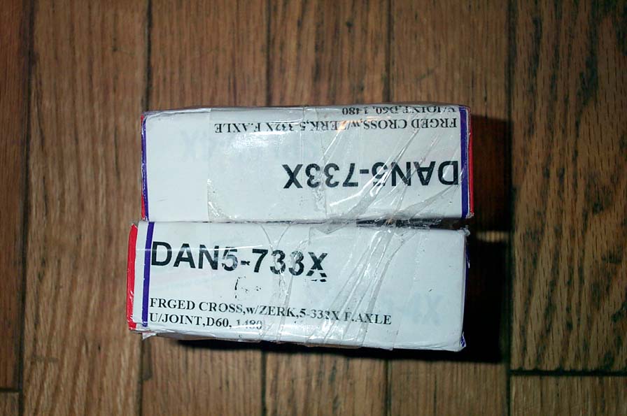 |
Spicer "Life Series" greasable 1480 series U-joints, Spicer part #: 5-733X. This is the same as part # SPL55-4x | ||||||||||||||||||||||||||||||||||||||||||
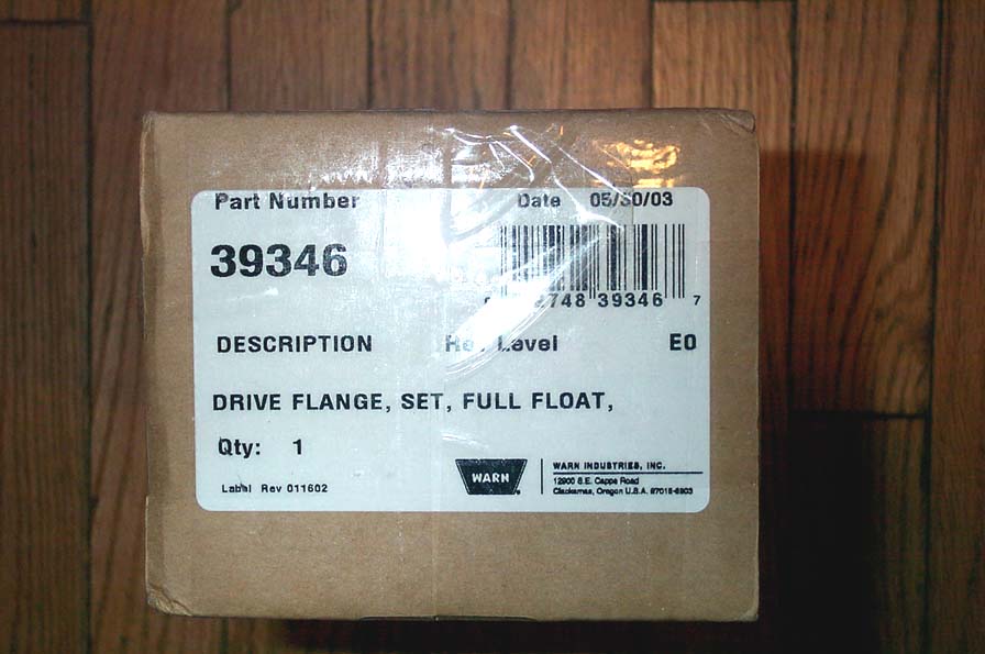 |
Warn 35 Spline Drive Flange kit, Warn part # 39346 | ||||||||||||||||||||||||||||||||||||||||||
|
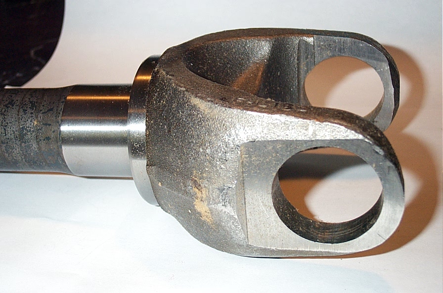
This is the 35 spline stub shaft. It is HUGE compared to the stock 30 spline stub shaft, and should net an approximate 40% increase in strength over the old stub. This is calculated using the formula:Yield Torque (in/lb)= Tensile Strength (psi) x polar moment of inertia/ radius of material and assumes same material and heat treat. | ||||||||||||||||||||||||||||||||||||||||||
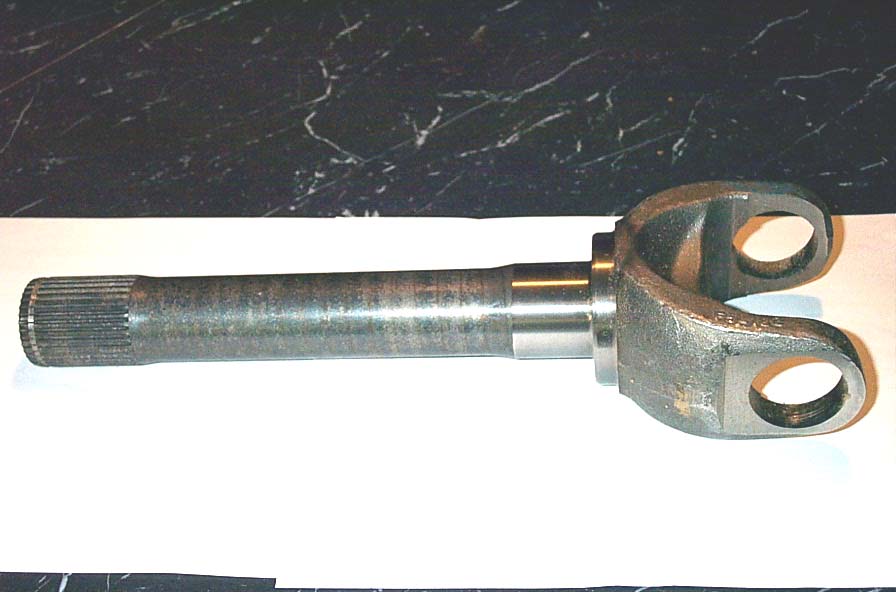 |
The Spicer shafts are made from SAE1137 steel (not a true "alloy steel") and are induction hardened. In this pic you can clearly see the blue circles along the shaft that show the hardening. From the "Machinery's Handbook": "Induction hardening is done by placing the metal part inside or close to an "applicator" coil of one or more turns, through which alternating current is passed. The coil, formed to suit the general class of work to be heated, is usually made of copper tubing through which water is passed to prevent overheating of the coil itself. In most cases, the work piece is held either in a fixed position or is rotated slowly within or close to the applicator coil. Where the length of work is too great to permit heating in a fixed position, progressive heating may be employed. Thus, a rod or tube of steel may be fed through an applicator coil of one or more turns so that the heating zone travels progressively along the entire length of the work piece. " |
||||||||||||||||||||||||||||||||||||||||||
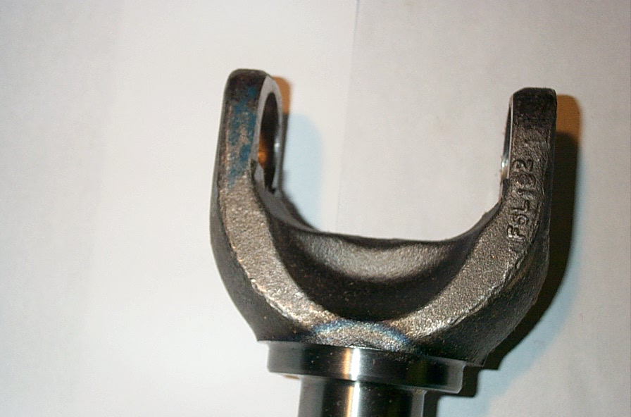 |
In this pic you can clearly see the bluing that indicates the limit to the induction hardening of the Spicer shafts. the shaft is passed through the coil, and the coil has to be of a small enough diameter so that it is close enough to the shaft to do the heating, but that diameter prevents the passage of the yoke through the coil. | ||||||||||||||||||||||||||||||||||||||||||
Some more pics of the stub shafts:
|
|||||||||||||||||||||||||||||||||||||||||||
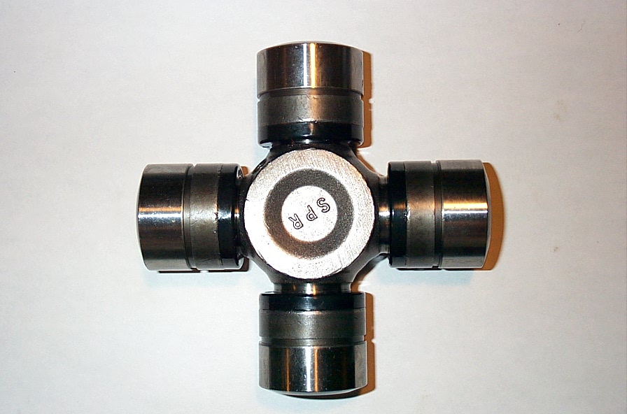 |
This is the Spicer Life Series 1480 series U-joint in greasable version. The older part number is Spicer part #: 5-733X, which has been superceded by part # SPL55-4x. They are the exact same part. Some shops are referring to these U-joints as "snap-tight" because the new triple-locks seal is so good, the caps snap on really tightly. Indeed, when I installed the U-joints, I had to use channel-lock pliers to remove the bearing caps from the trunnions - I couldn't pull them off by hand - that's how good the seals are. | ||||||||||||||||||||||||||||||||||||||||||
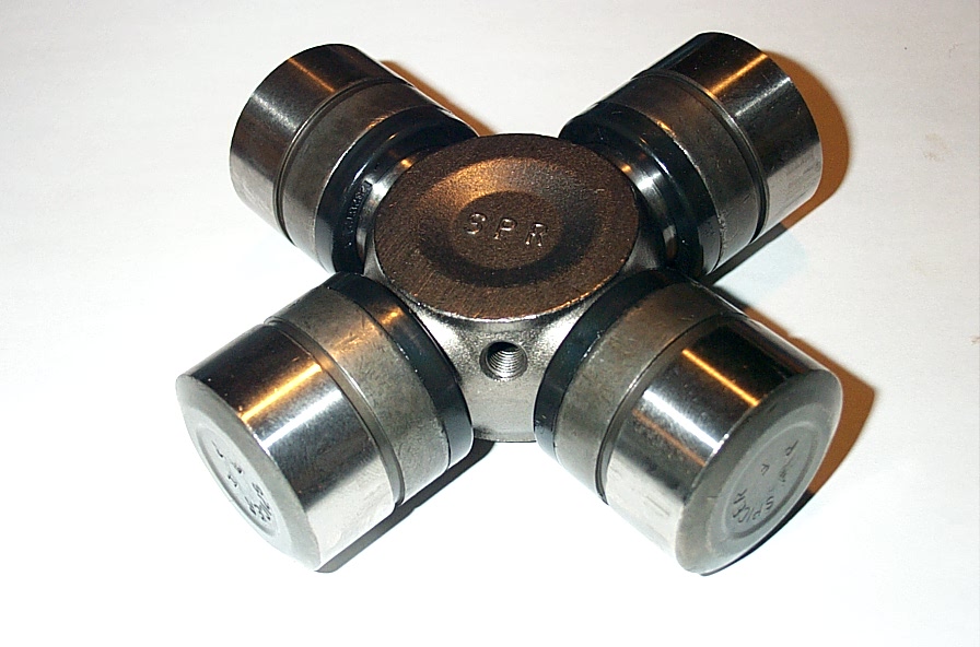 |
A great deal has been made of these "new" style Spicer joints in the last year or so. You will often see them referred to as the "new forged' or "cold formed" U-joints. This is a bit of a misnomer, I think, because, as far as I know, Spicer U-joints have always been forged. Spicer refers to them as the "Spicer Life" series. They do claim a 50% greater life due to the improved seal. |
||||||||||||||||||||||||||||||||||||||||||
 |
And they also mention "greater torque carrying capacity", but give no figures on this. The greater strength in part comes from the reduced diameter of the grease holes, as seen in this pic. manufacturing process, metallurgy, heat treating, and quality control procedures may all play a part as well. Some conservative shade-tree estimates have been made at 20-30% strength increase over the old style U-joints. I personally have no idea if this is true or not, not having the equipment to run proper testing myself. |
||||||||||||||||||||||||||||||||||||||||||
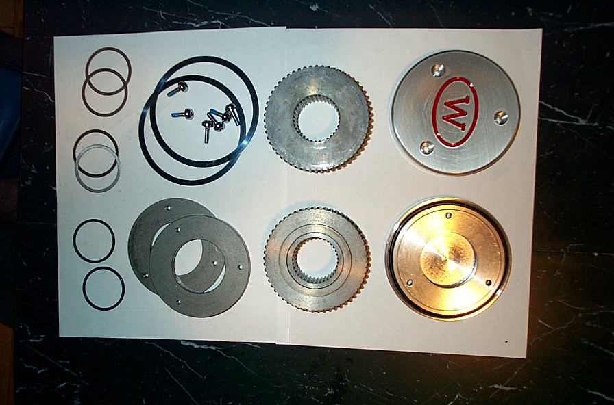 |
This is the contents of the Warn 35 Spline drive flange kit. When I spoke to Greg, I hemmed and hawed about whether to go with Warn 35 spline lockouts or drive flanges. On the one hand - the lockouts are nice because of the flexibility they offer, especially for a street driven or spooled front rig. On the other hand, the drive flanges are undeniably simpler and MUCH stronger. In the end I went with simplistic and brute strength - was there ever really any question :-) |
||||||||||||||||||||||||||||||||||||||||||
 |
Whichever you decide, you do have to purchase new 35 spline lockouts or drive flanges, as your old 30 spline units will not fit on the new stub shafts. | ||||||||||||||||||||||||||||||||||||||||||
 |
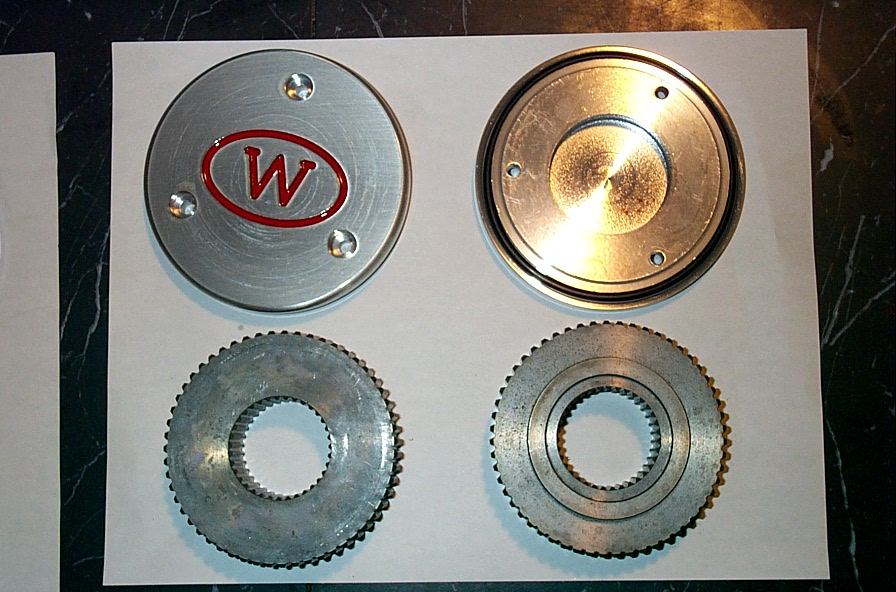
If you have 30 spline drive flanges, you may be able to find a machine shop that can broach then to 35 spline for you. The caps have a nice large O-ring seal, and secure with 3 simple Torx screws. |
||||||||||||||||||||||||||||||||||||||||||
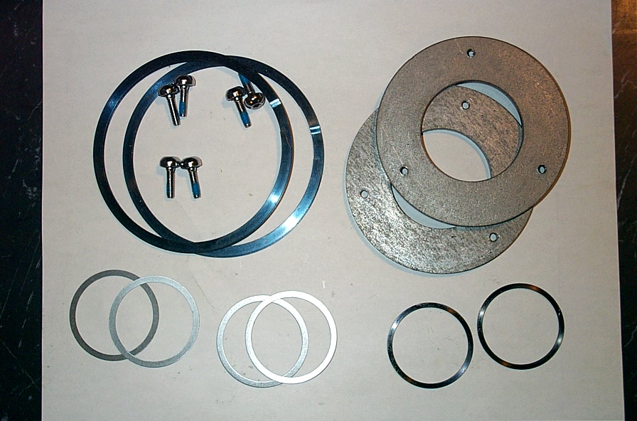 |
The kit also comes with (L top R, top to bottom) large hub snap rings, cap screws with impregnated thread locking compound, cap retention plates (to which the caps secure- see installation later in article), 4 thrust/wear washers (2 for each side), and a pair of small stub shaft snap rings. | ||||||||||||||||||||||||||||||||||||||||||
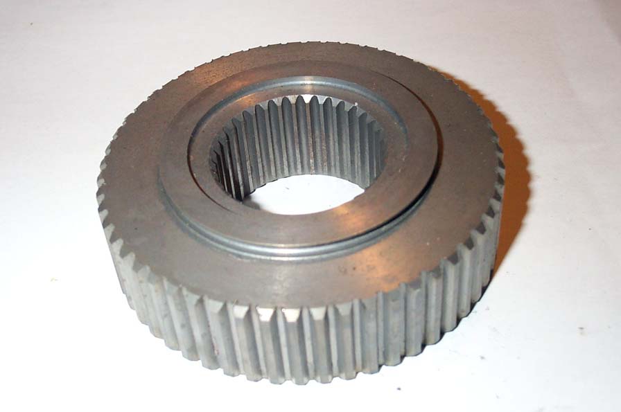 |
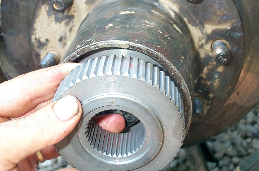
Close-up of the drive flange itself. | ||||||||||||||||||||||||||||||||||||||||||
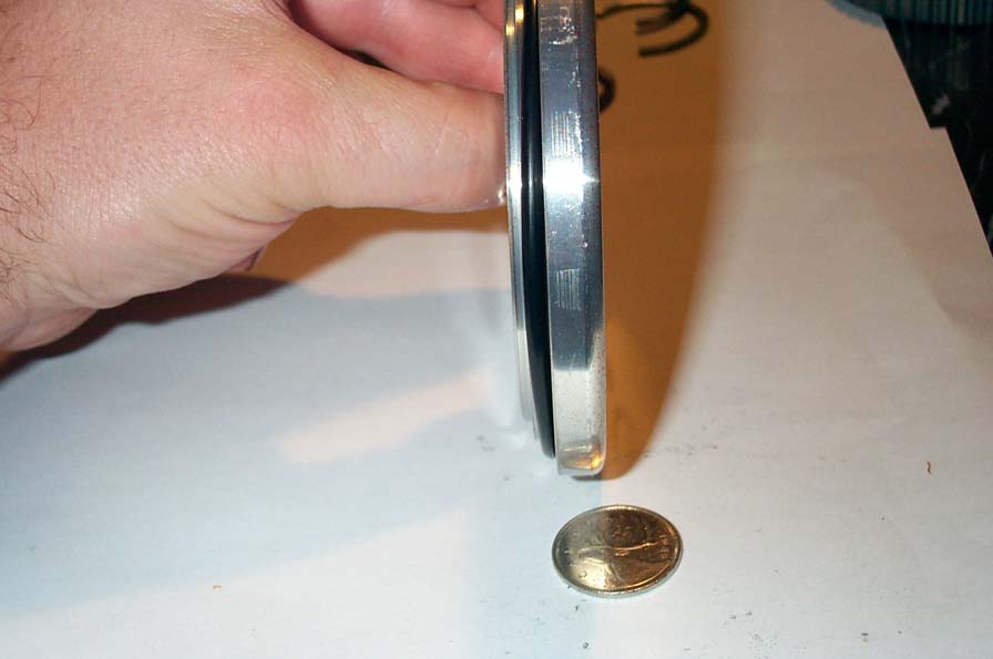 |
This shows one of my favourite parts of the kit. The Warn drive flange caps are VERY thin (that's a quarter in the picture), which means they stick out of the hub MUCH less than any manual lockout would, which saves them from abuse amongst the rocks. | ||||||||||||||||||||||||||||||||||||||||||
 |
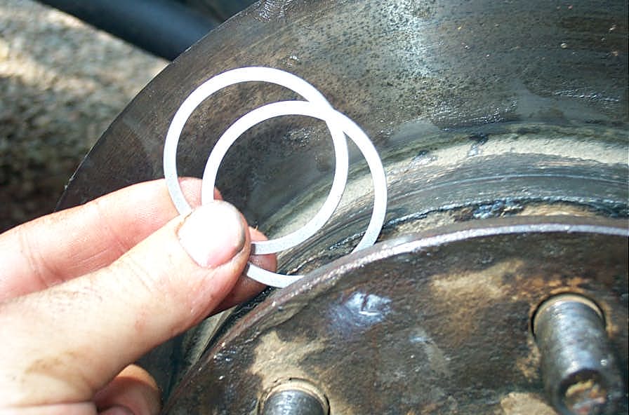
The snap rings included are the "thin multi-wind" type. | ||||||||||||||||||||||||||||||||||||||||||
 |
I much prefer these to the other type, because you can install and remove them without requiring snap ring pliers - just a small screwdriver will do. | ||||||||||||||||||||||||||||||||||||||||||
 |
Complete 35 spline stub axle upgrade kit. | ||||||||||||||||||||||||||||||||||||||||||
 |
Complete 35 spline stub axle upgrade kit. | ||||||||||||||||||||||||||||||||||||||||||
Part 2 - Teardown |
|||||||||||||||||||||||||||||||||||||||||||
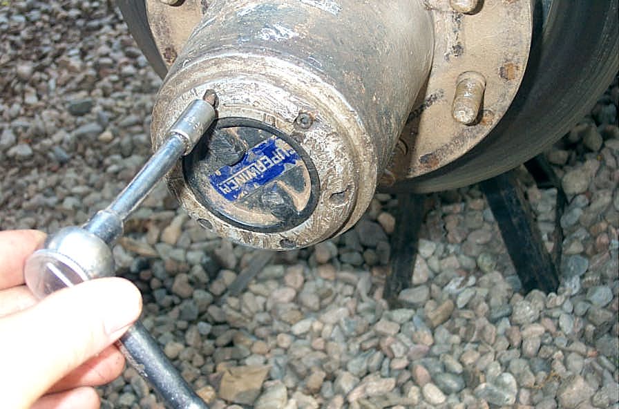 |
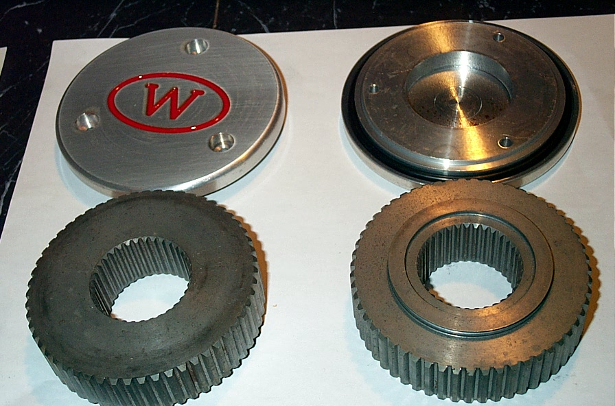
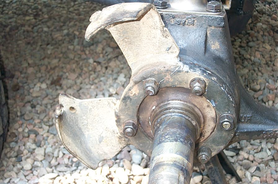
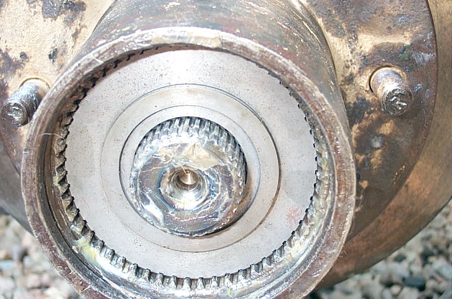
Start by removing the 6 small bolts that hold the manual lockout cap on. They may be allen head or Torx bits, depending on brand / age. Just look at that tired, beat up hub cap. I will not be sad to see the end of hassling with these things. The Warn drive flange caps stick out far less from the end of the hub. |
||||||||||||||||||||||||||||||||||||||||||
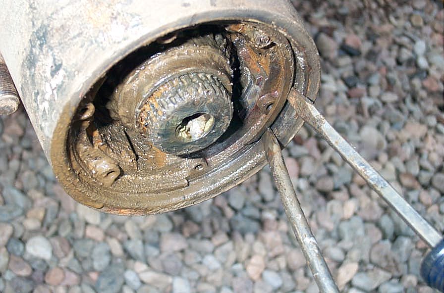 |
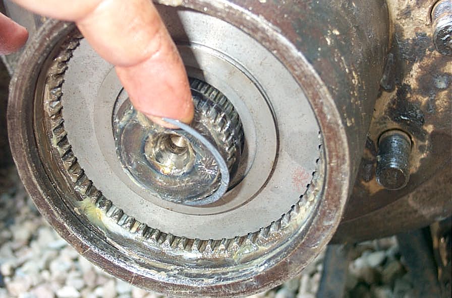
Once you have the cap off, remove the 2 snap rings - one on the stub axle, and one just inside the hub. I find the "2 screwdriver" method the best to lever out the big snap ring just inside the hub. Some patience is required. The small snap ring in the end of the stub shaft can be removed with a screwdriver, or with snap ring pliers if it is the type with the holes for the pliers. |
||||||||||||||||||||||||||||||||||||||||||
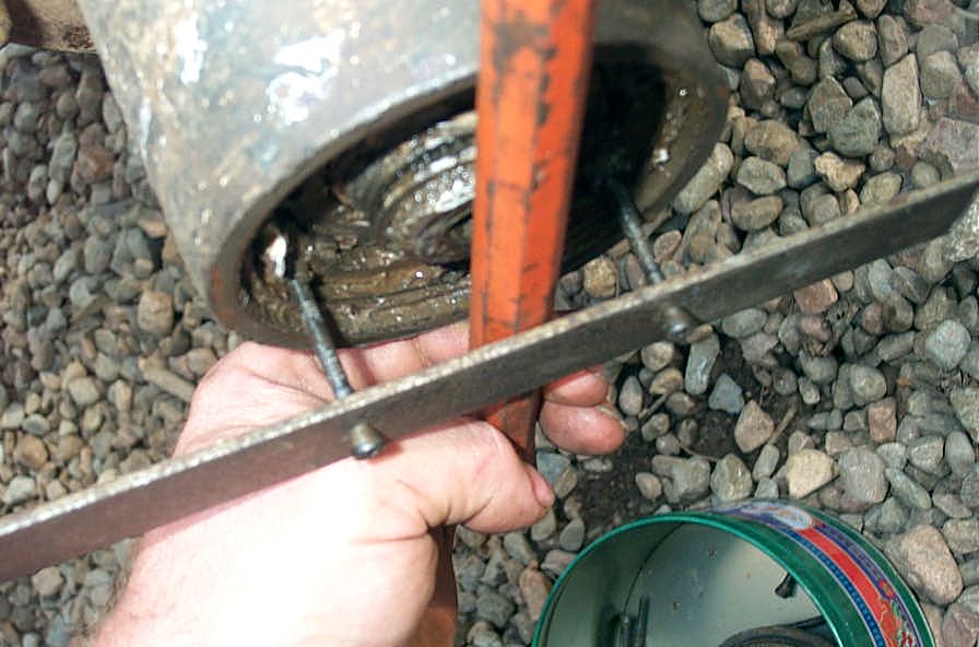 |
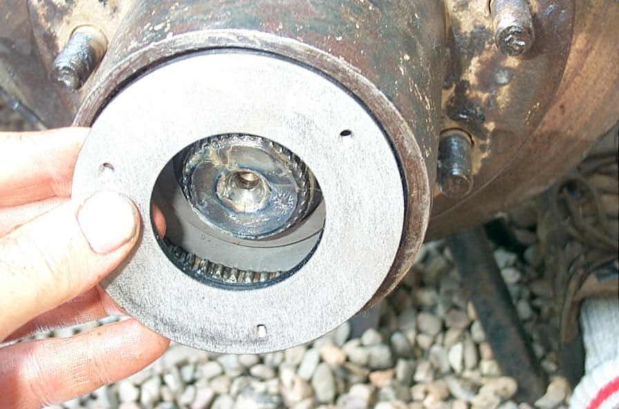
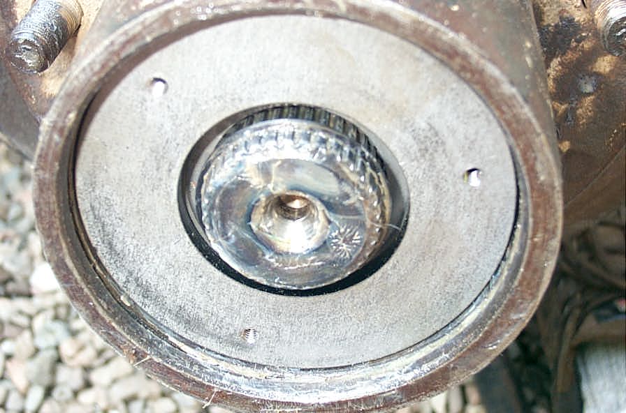
Once the snap rings are out, you can remove the body of the manual lockout hub. If it is stubborn (as most will be), you can easily fabricate a hub removal tool. I used a scrap piece of 1" strap, drilled to take 2 of the hub cap screws, and a big chisel behind it. To use it, just screw 2 screws back into the hub through the tool, then put a bar or chisel behind it and yank out the hub. An interesting note, if you drill the holes in the scrap for 2 adjacent holes in a D60 hub, it will also work for D44 hubs, 3 holes apart. |
||||||||||||||||||||||||||||||||||||||||||
| [NOTE: My photos didn't turn out for the next 4 pics, so the photos shown are actually a full-float rear axle, but the parts are exactly the same for this step, so bear with me] | |||||||||||||||||||||||||||||||||||||||||||
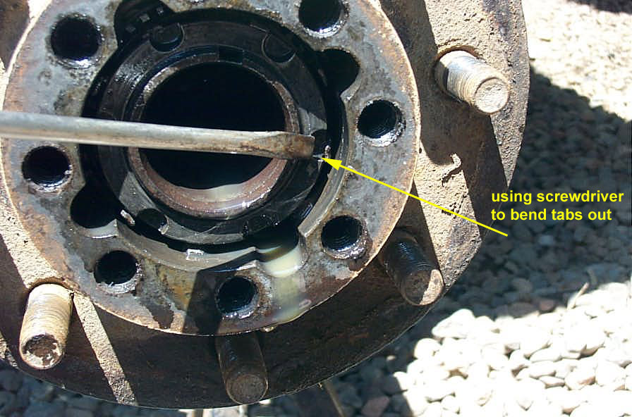 |
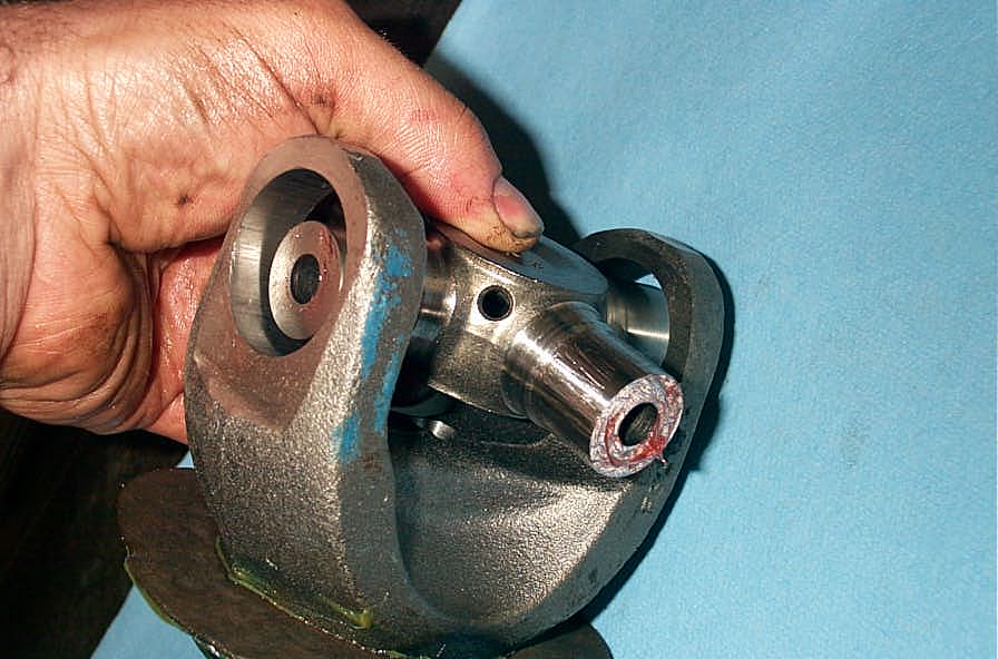
Once you have the locking hub removed, the hub will look like this. Bend the little tabs on the spindle lock-washer outwards so the outer spindle lock nut can be removed. | ||||||||||||||||||||||||||||||||||||||||||
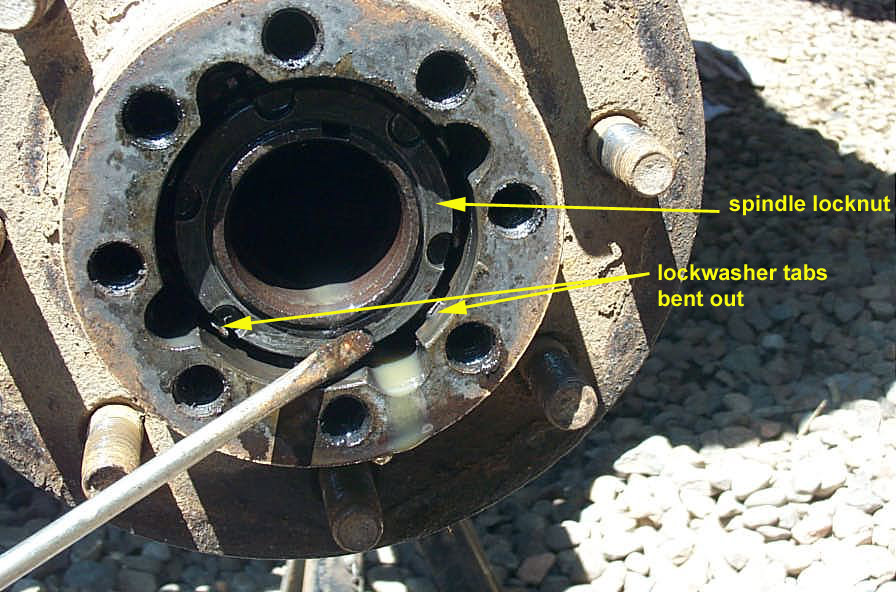 |
The proper way to remove and install the spindle nuts is to use the proper 6-slot socket. of course, if you're a high-tech redneck like me, you can bang them out with a hammer and screwdriver! Note - there are a huge number of different lock washer and spindle nut arrangements out there. Some are 6 slot as shown some are 4 slot, some are a large hex head and some are a special rounded hex head. Also, some lock washers use tabs as shown, and some have holes that index onto little "tits" on the spindle nuts. You will have to adapt, improvise, overcome. |
||||||||||||||||||||||||||||||||||||||||||
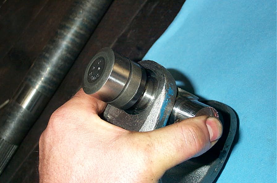
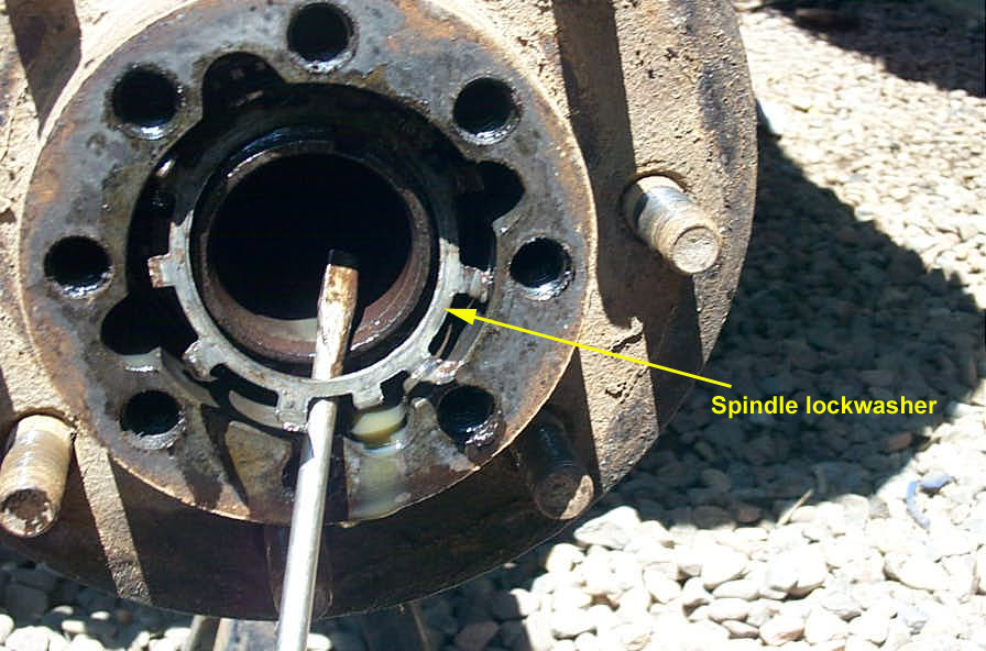 |
Once the outer lock nut is removed, fish out the lock washer with a screwdriver / pick. | ||||||||||||||||||||||||||||||||||||||||||
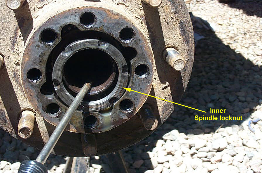 |
And then the inner nut can be removed. Behind the inner nut will be a flat, indexing washer. Once you have fished all that out and set it aside carefully, you are almost ready to pull the whole hub/rotor assembly off the spindle. | ||||||||||||||||||||||||||||||||||||||||||
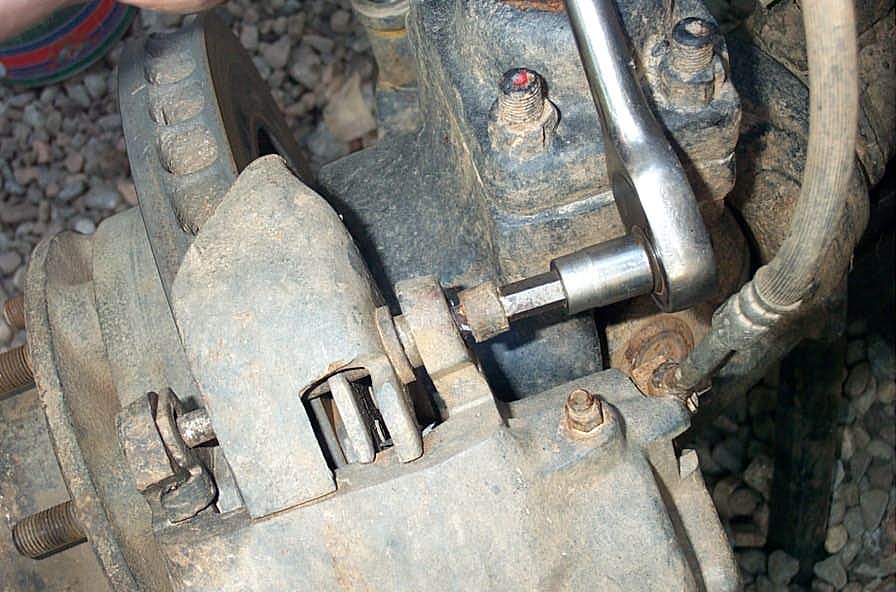 |
But first you have to remove the brake calipers. There are several different styles. You may have to remove caliper slide bolts as I did, or you may have to remove a grub screw and knock out some locating wedges. | ||||||||||||||||||||||||||||||||||||||||||
 |
Once you have the caliper removed, and the hub/rotor assembly pulled off (careful not to drop the outer wheel bearing in the dirt as you slide the hub/rotor off), this is what you are left with. | ||||||||||||||||||||||||||||||||||||||||||
 |
Remove the nuts that secure the brake caliper mounting bracket and spindle to the knuckle. | ||||||||||||||||||||||||||||||||||||||||||
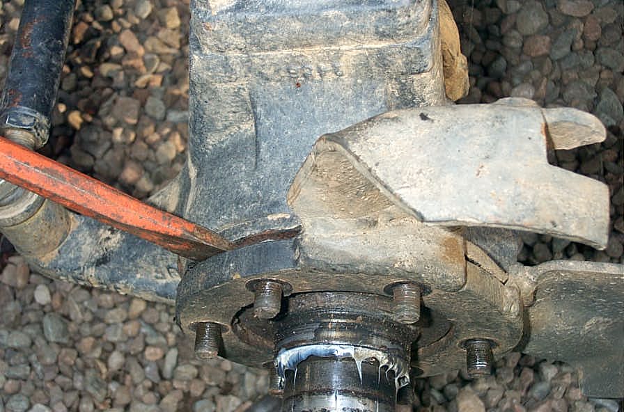 |
On a Chevy Dana 60, the brake caliper bracket comes off first. I persuaded it with a large chisel. But be careful not to beat things to death. | ||||||||||||||||||||||||||||||||||||||||||
 |
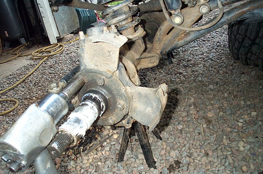
Finally, you can tap off the spindle. You can use a soft-faced hammer to tap on the spindle itself, but do not strike a bearing surface. On the GM Dana60, there is a notch in the knuckle to allow for the large single-caliper 1 ton brake calipers, and it provides a place to carefully strike the back side of the spindle to help loosen / remove it. | ||||||||||||||||||||||||||||||||||||||||||
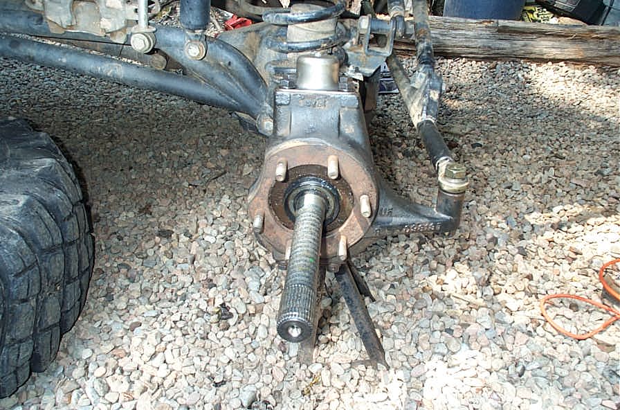 |
The final step is simply to grab the shafts, and gently slide them from the housing. Be careful as you remove them from the housing, so as to avoid damaging the inner axle seals. |
||||||||||||||||||||||||||||||||||||||||||
 |
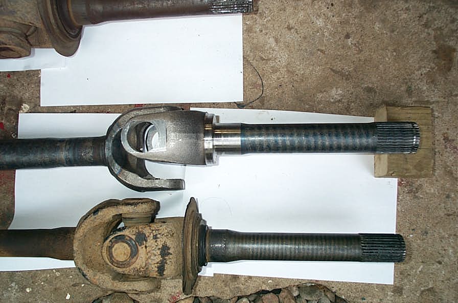
When you are all done, you'll have the old axles removed, and ready to be replaced. But first, let's compare the old with the new, to make sure we're not just replacing these parts because it's the latest cool thing to do, but because there's a good reason. |
||||||||||||||||||||||||||||||||||||||||||
Part 3 - Old vs New shaftsPlease note that all dimensions and measurements quoted here were measured by me with a pair if inexpensive digital calipers. They are likely only accurate to within +/- .020 inches, and should not be used for precise machining purposes or exact layout. They do however clearly illustrate comparative differences. |
|||||||||||||||||||||||||||||||||||||||||||
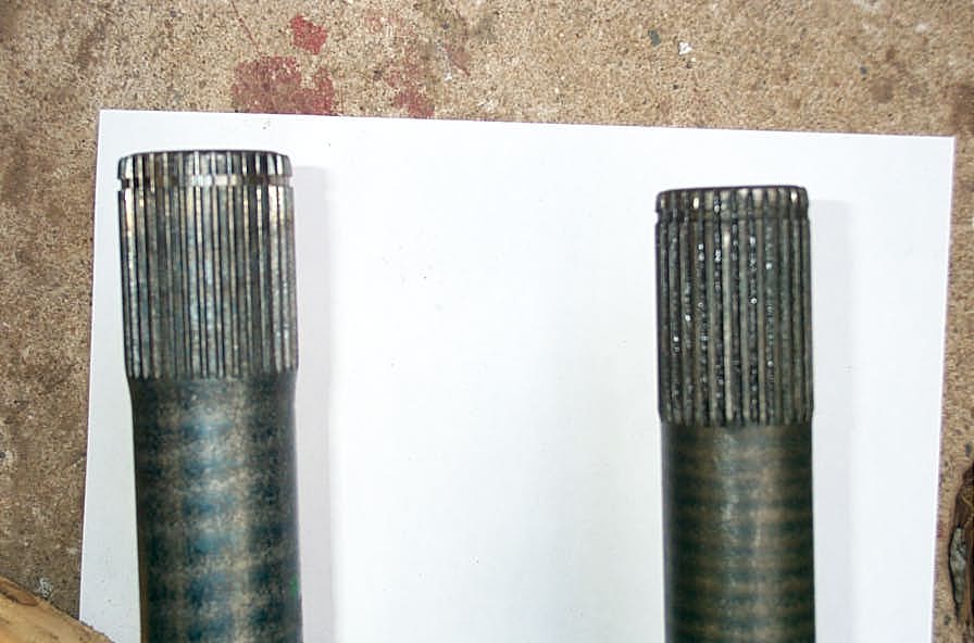
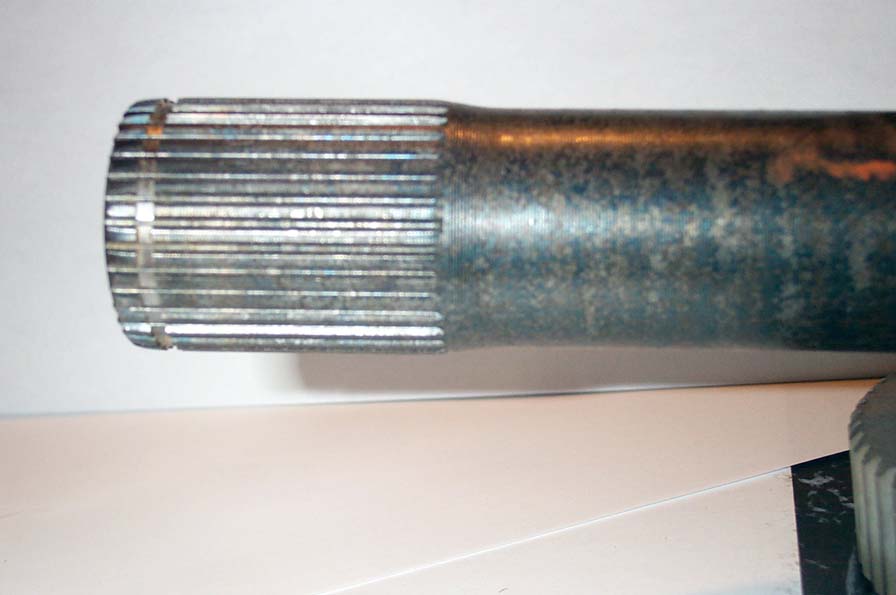
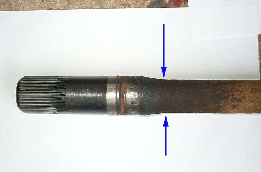 |
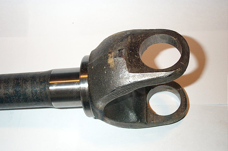
Here's the spline end of the original, pre 1981 stock long-side inner front GM Dana60 shaft. Prior to 1981 was when the shafts "necked down", which you can clearly see in the picture. One other thing is well illustrated here. On an older axle shaft, even a 1981 and later "big" shaft, there will likely be a lot of wear and corrosion. this can be a significant weakness, as very often, when a shaft breaks, it does so at a place where there is a stress riser - frequently caused by surface corrosion, nicks, or flaws. That's why Drag racers polish their shafts to a mirror finish - to remove surface stress risers. |
||||||||||||||||||||||||||||||||||||||||||
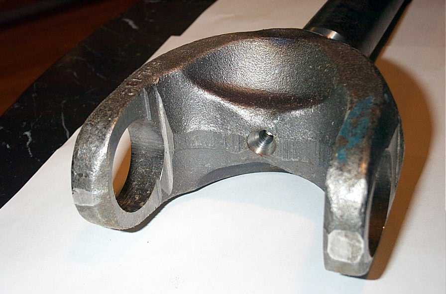
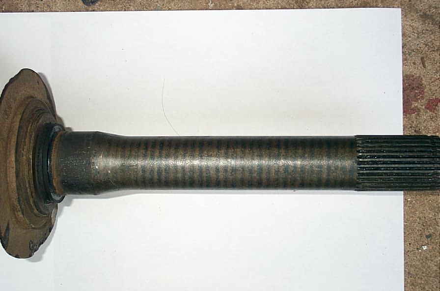 |
This pic of the stock Dana60 front 30 spline stub shaft also clearly shows where it reduces in diameter to about 1.258" It also shows quite well the "bluing" marks on the body of the shaft created as the shaft passes through the coil in the induction hardening process. |
||||||||||||||||||||||||||||||||||||||||||
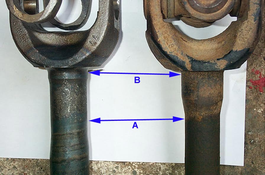
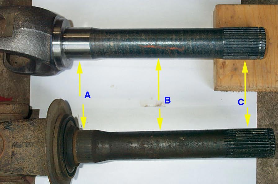 |
Here's a comparison shot of the Dana60 30 spline stub shaft versus the 35 Spline Dana70 stub shaft. Note that both are exactly 12.0 inches long. The other dimensions in the pic are:
|
||||||||||||||||||||||||||||||||||||||||||
 |
Another shot of the 2 stub shafts, clearly showing how much bigger the 35 spline stub shaft is. | ||||||||||||||||||||||||||||||||||||||||||
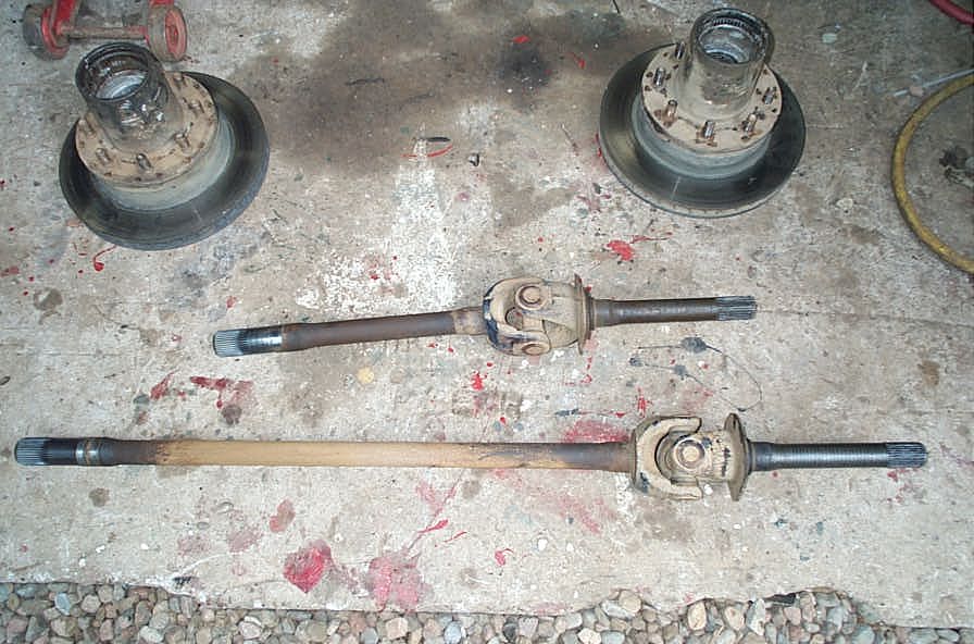
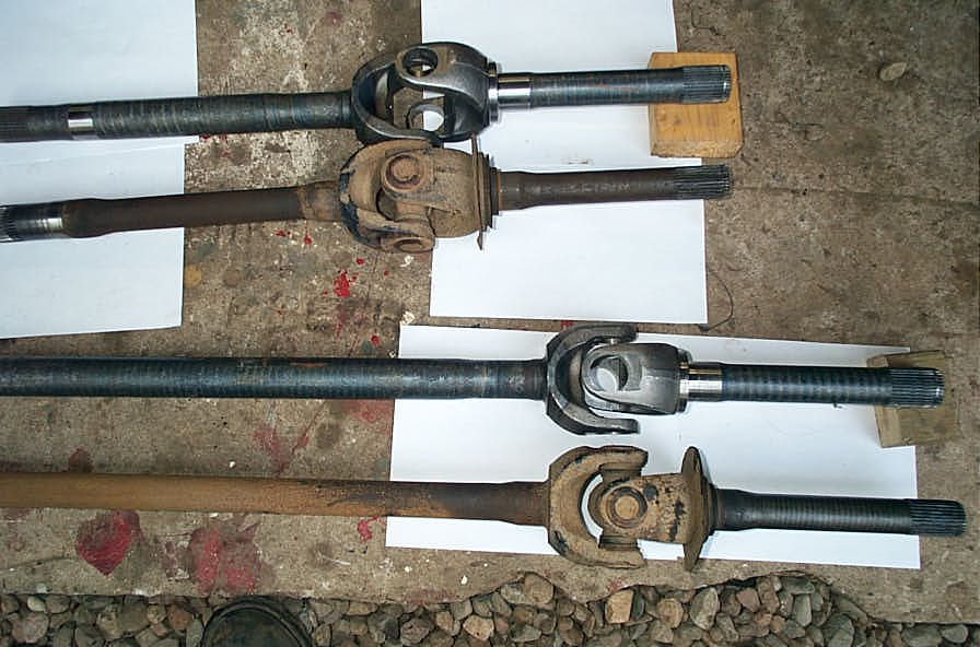
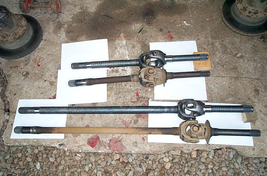 |
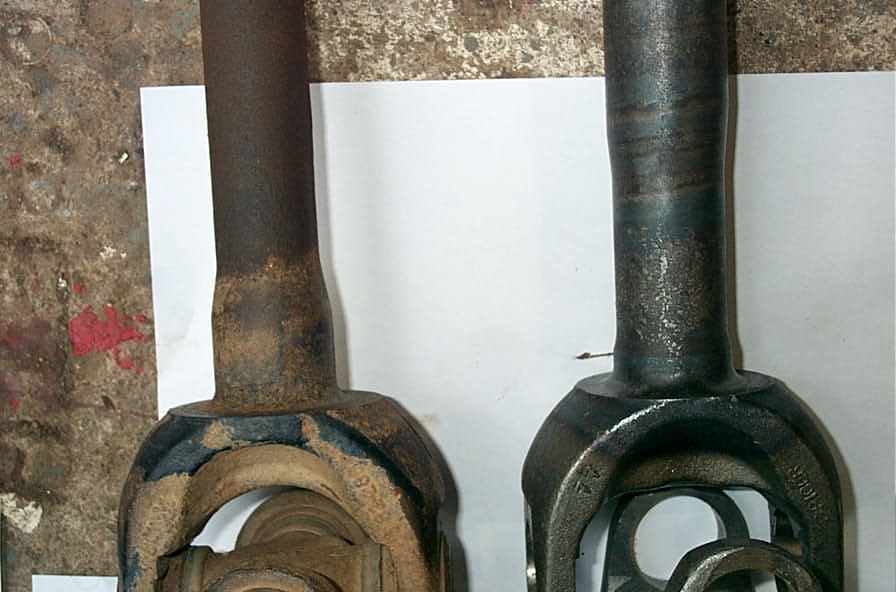
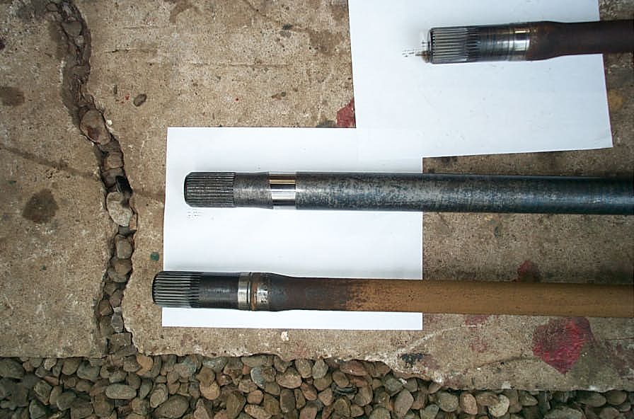
All the old next to all the new. | ||||||||||||||||||||||||||||||||||||||||||
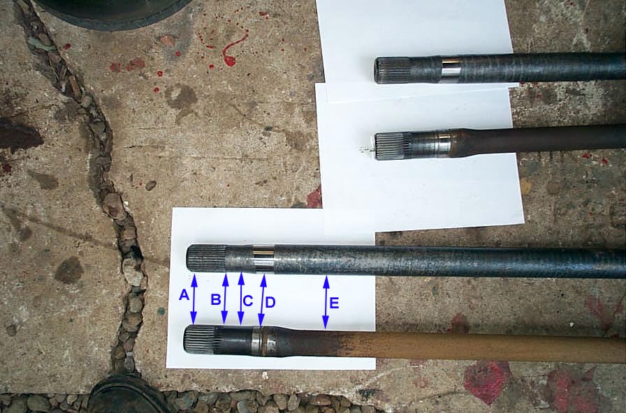 |
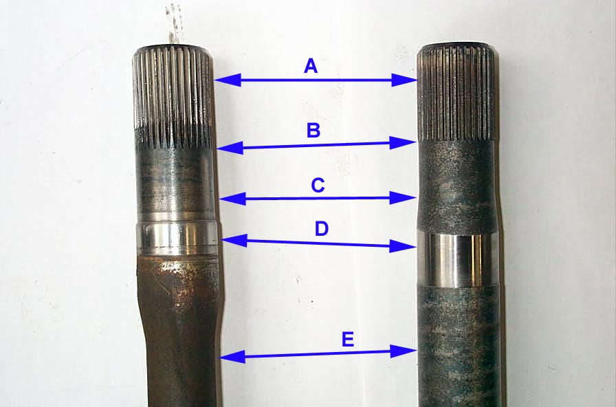
Comparison of old and new long-side inner shafts:
|
||||||||||||||||||||||||||||||||||||||||||
 |
Comparison of old and new short-side inner shafts:
|
||||||||||||||||||||||||||||||||||||||||||
| It seems odd, and I have no hard factual or tech data to back this up, but the splines on the old shaft actually "look better" to me. I don't know if they actually are or not. But the real story is the dimension "E" - much larger on the newer shafts! | |||||||||||||||||||||||||||||||||||||||||||
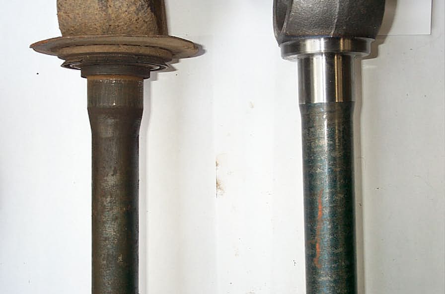
 |
This comparison is actually an interesting optical illusion. Because the main operating diameter of the newer shafts is so much bigger than in the older shafts, it actually appears as if the newer shafts are smaller at the yoke. this is not actually true, and they are bigger, or at least the same size as the old shafts... | ||||||||||||||||||||||||||||||||||||||||||
 |
...as this picture and table illustrates. These are the long-side inner axles.
|
||||||||||||||||||||||||||||||||||||||||||
 |
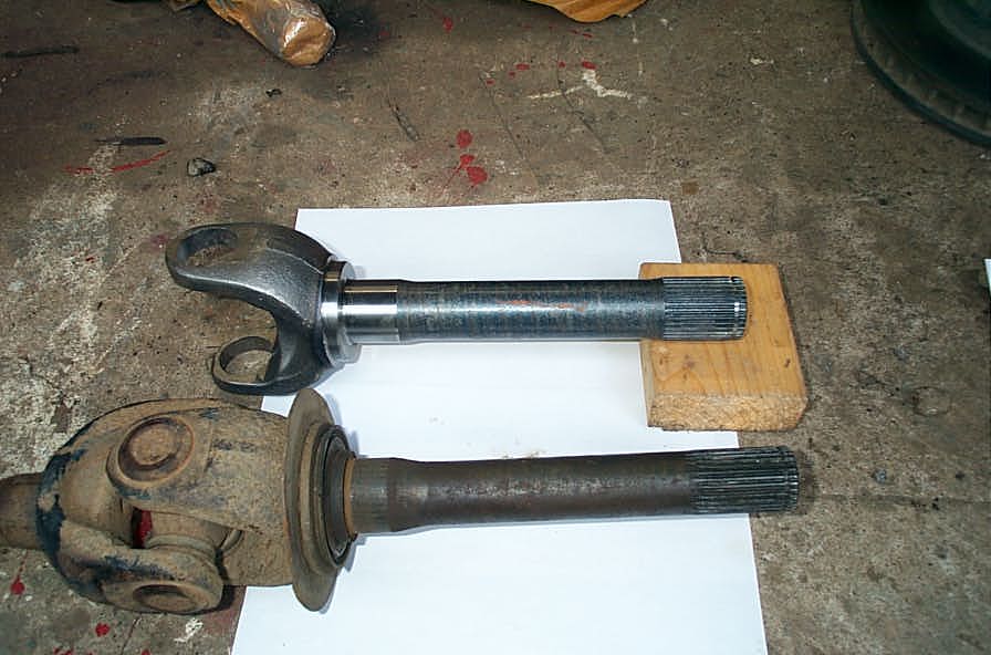
35 spline stub on the left, stock 30 spline on the right. Reason enough to buy the kit right there! |
||||||||||||||||||||||||||||||||||||||||||
Here are a bunch more comparison pics:
So it seems pretty clear, based on size, condition, lack of corrosion, and very likely improved manufacturing techniques and metallurgy over 25 years or more, that the new "big" inner axles and 35 spline stub shafts are a real and significant upgrade. Part 4 - Assembling New Shafts and U-joints |
|||||||||||||||||||||||||||||||||||||||||||
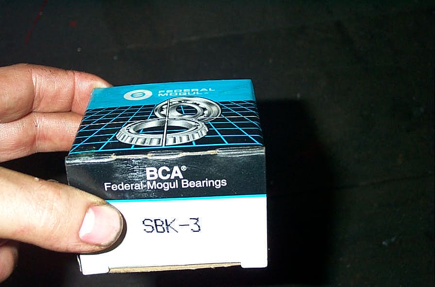 |
No sense in installing those shiny new shafts with a bunch of old, rotted out seals and rusty bearings. I purchased 2 spindle seal and bearing kits locally. They can be a bit of a bear to find, so if you're reading this Greg, it might be an idea to offer them as an add-on to the 35 spline kits. I for one highly recommend using all new bearings and seals, especially while you have everything apart. |
||||||||||||||||||||||||||||||||||||||||||
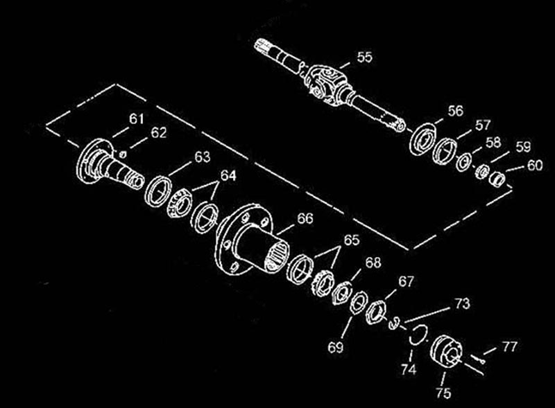 |
Here is an exploded diagram and part numbers for the seals and bearings:
|
||||||||||||||||||||||||||||||||||||||||||
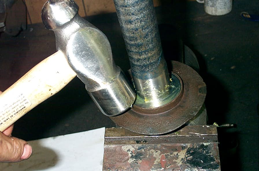
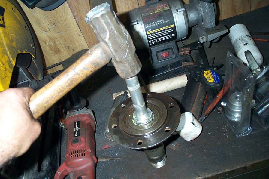 |
I use a small aluminum bearing/seal driver and a BFH to install the new "Torrington" needle bearing into the back side of the spindle. Don't ask how I got the old ones out - it was an embarrassing, frustrating, and altogether not very technical mixture of heat, blunt objects, brute force and cussing. - in other words - nothing at all you could learn from! |
||||||||||||||||||||||||||||||||||||||||||
 |
The metal "dust shields" or "stone guards" or "slingers" are not included in the spindle kit (but everything else is), so they have to be removed from the old stub shafts and reused. Alternatively you can order new ones - the Spicer part number is 37308 (for GM and Dodge), and I expect the Ford are exactly the same. |
||||||||||||||||||||||||||||||||||||||||||
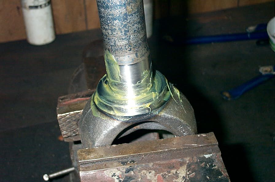 |
Grease the new stub shaft liberally. | ||||||||||||||||||||||||||||||||||||||||||
 |
Tap the stone guard into place. | ||||||||||||||||||||||||||||||||||||||||||
 |
Then place the inner spindle seal on with the lip facing out. | ||||||||||||||||||||||||||||||||||||||||||
 |
Next place the thrust washer on with the "chamfer" facing in (or the perfectly flat side facing out). | ||||||||||||||||||||||||||||||||||||||||||
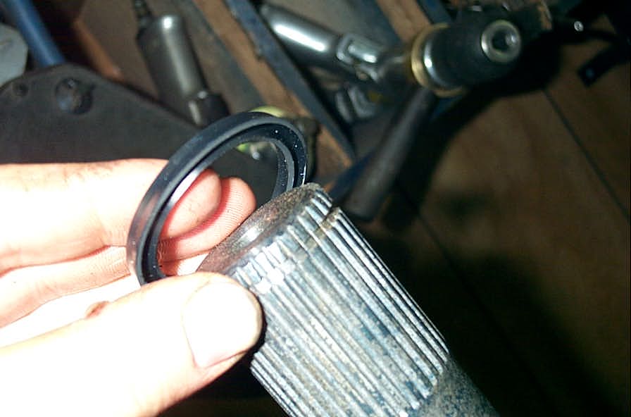 |
And finally, place the outer spindle seal on with the lip facing in. | ||||||||||||||||||||||||||||||||||||||||||
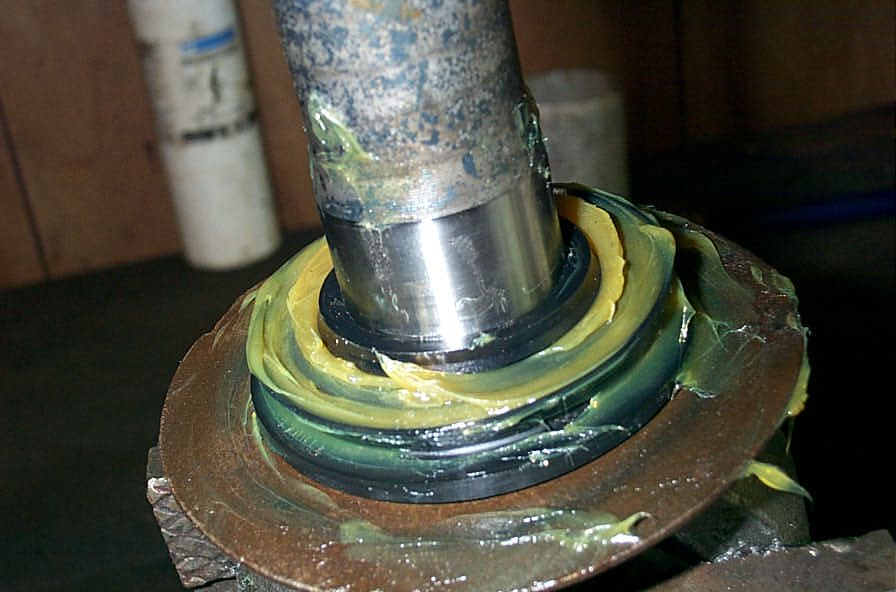 |
Then grease everything liberally, ready to go into the back of the spindle. | ||||||||||||||||||||||||||||||||||||||||||
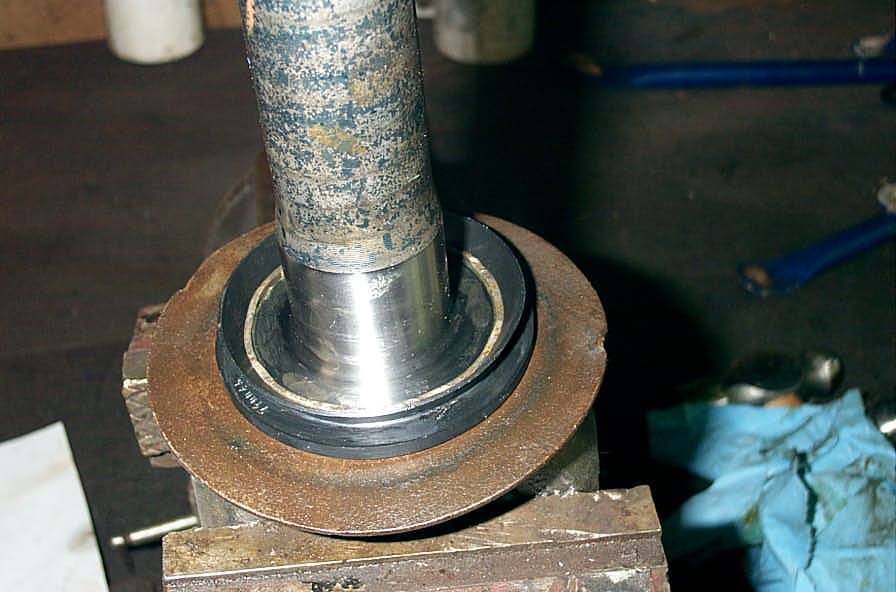
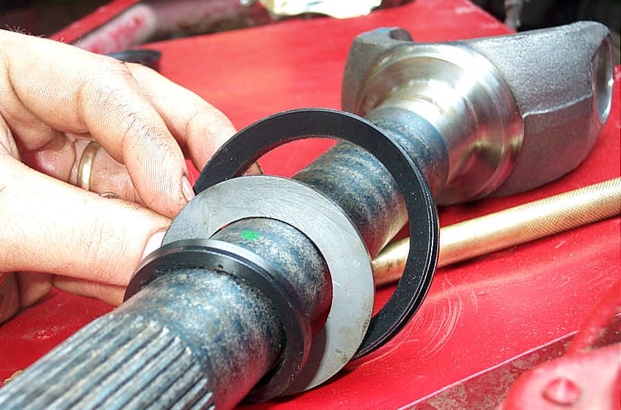 |
This picture clearly shows the order and orientation of the seals and washer. | ||||||||||||||||||||||||||||||||||||||||||
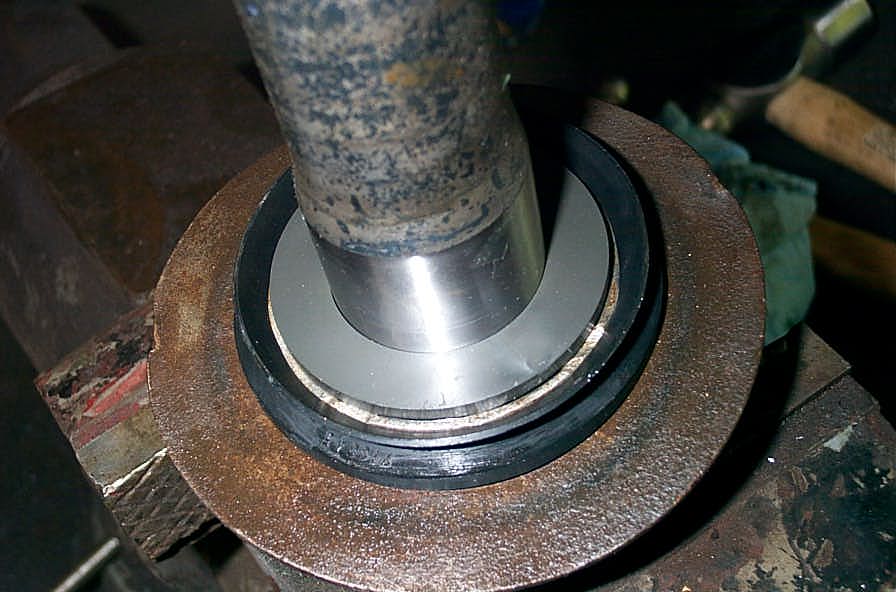
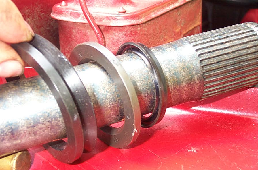 |
Another view of the order and orientation of the seals and washer. | ||||||||||||||||||||||||||||||||||||||||||
| Once you have the stub shafts all geared up, it's time to assemble the inner and stub shafts with the new U-joints. | |||||||||||||||||||||||||||||||||||||||||||
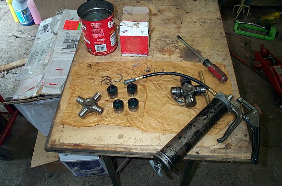 |
You will need a reasonably clean workspace, a grease gun, a large hammer, a large socket, and a small standard screwdriver. | ||||||||||||||||||||||||||||||||||||||||||
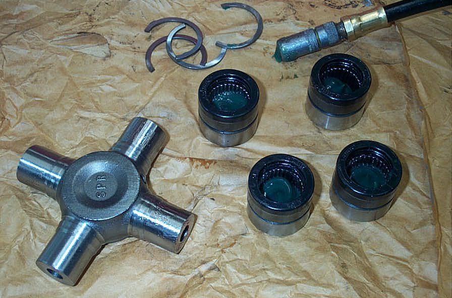 |
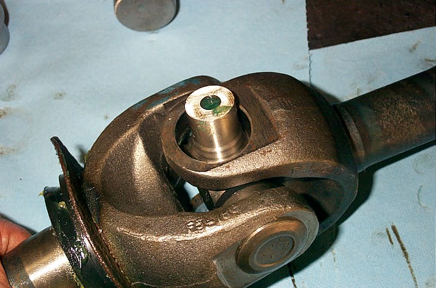
First, remove all the bearing caps from the trunnions of the cross. With the new Spicer Life Series U-joints, the seals are so good you may have to use pliers to remove the caps - they are extremely hard to remove by hand. Place a moderate amount of grease in each cap. Do not go overboard, as excess grease in the cap during assembly will cause excessive hydraulic force and make assembling the U-joint very difficult. I just put a good dab in the cap then wipe it around the needle bearings with a finger. the joint will be fully greased after assembly. |
||||||||||||||||||||||||||||||||||||||||||
 |
Place the cross in the bores of the yoke of the stub shaft, with the grease nipple hole facing in (towards the inner shaft). | ||||||||||||||||||||||||||||||||||||||||||
 |
Raise the trunnion up in the bore and place a bearing cap on it. | ||||||||||||||||||||||||||||||||||||||||||
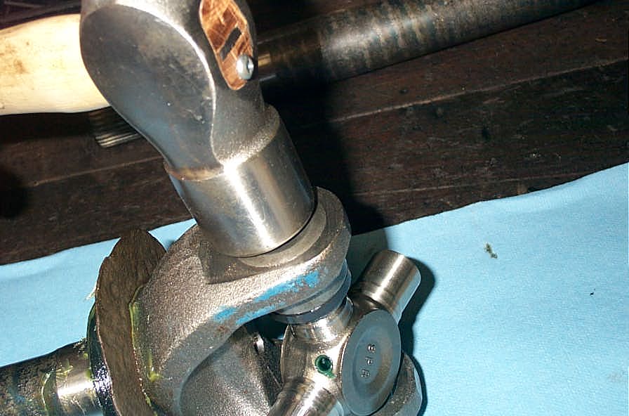 |
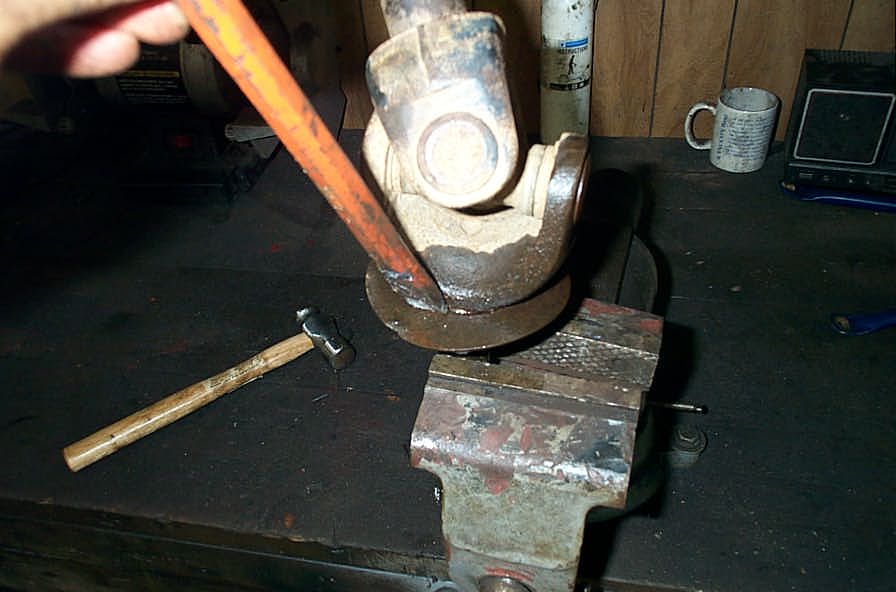
Drive the cap into the bore with a hammer... | ||||||||||||||||||||||||||||||||||||||||||
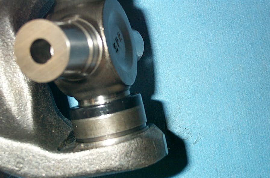 |
...until the groove in the cap for the snap ring is visible inside the yoke. | ||||||||||||||||||||||||||||||||||||||||||
 |
Tap the snap ring into place. | ||||||||||||||||||||||||||||||||||||||||||
 |
Raise the opposite trunnion up in it's yoke bore. | ||||||||||||||||||||||||||||||||||||||||||
 |
Place its bearing cap on. | ||||||||||||||||||||||||||||||||||||||||||
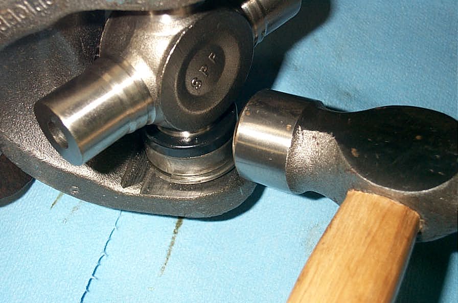
 |
Then place the yoke, with the bearing cap that already has its snap ring installed, on a large socket whose ID is larger than the OD of the bearing cap... | ||||||||||||||||||||||||||||||||||||||||||
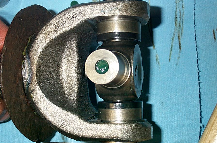 |
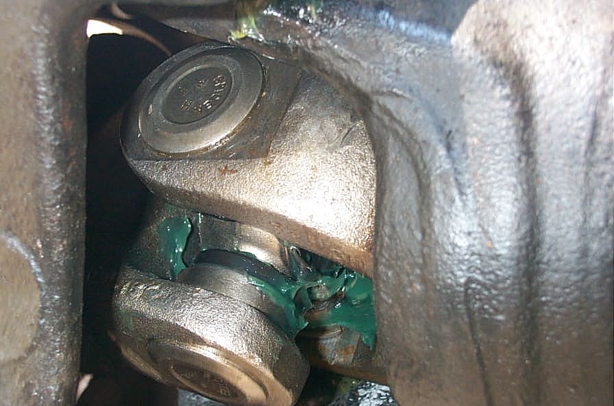
...and tap the other bearing cap into its bore until the snap ring can be inserted With both snap rings installed, rotate the cross and check for binding. |
||||||||||||||||||||||||||||||||||||||||||
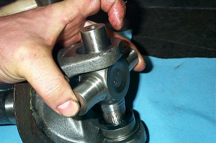
 |
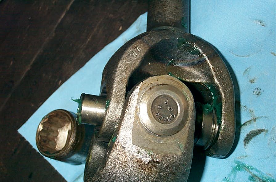
If the joint is tight, you can attempt to relieve pressure by striking the ear of the yoke sharply. If this fails to allow the joint to rotate firmly (not sloppily) but without binding or over-tightness, you will have to disassemble and inspect. It is likely that one of the caps may have a toppled needle bearing. | ||||||||||||||||||||||||||||||||||||||||||
 |
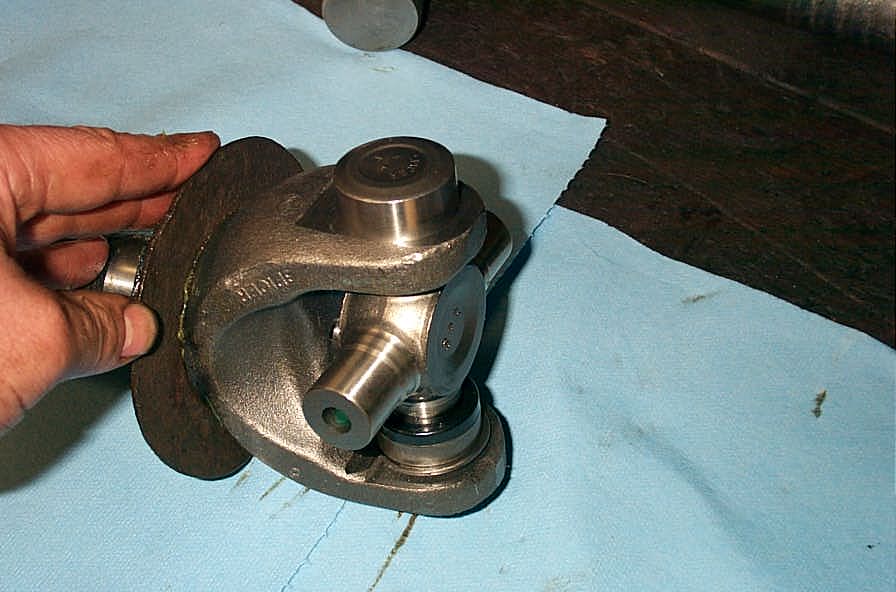
Place the stub shaft with U-joint installed into the inner shaft yoke so that one of the trunnions protrudes through the top of the bore. Then essentially repeat the entire procedure as above to install the other 2 bearing caps. |
||||||||||||||||||||||||||||||||||||||||||
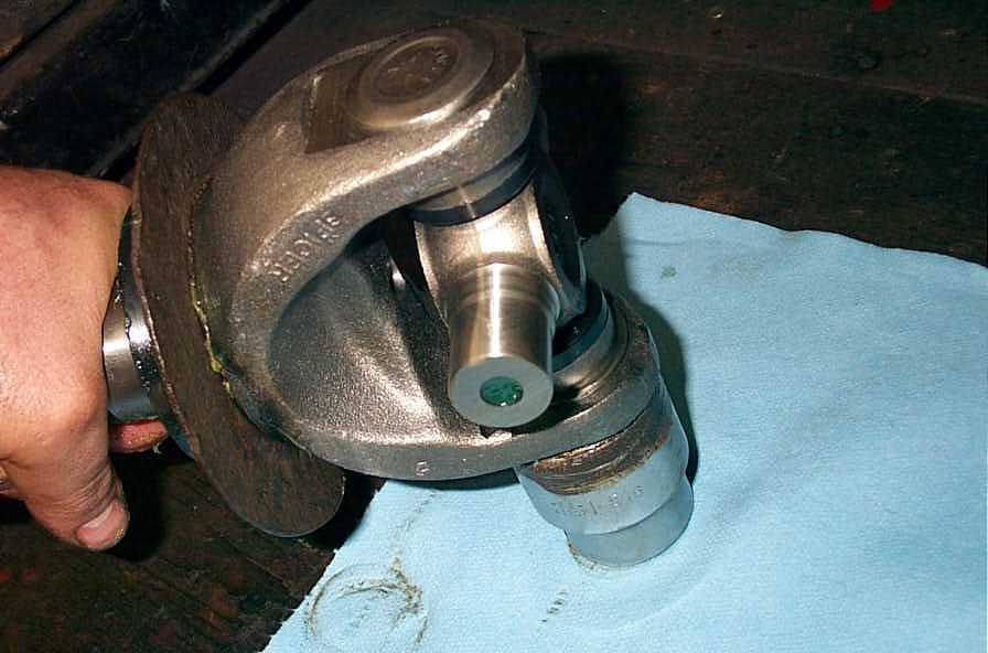
 |
Here the last bearing cap is about to be installed. | ||||||||||||||||||||||||||||||||||||||||||
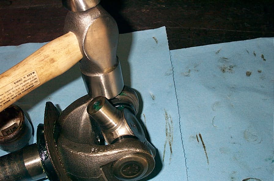
 |
Be careful when installing the snap rings that they are straight and properly seated in the groove, otherwise you will bend one, like I did here, as you drive on the opposite bearing cap. Doh! When all the caps are on and clips installed, install the grease nipple, the grease the joint until fresh grease purges from all 4 seals. Then do a final check for any binding in the U-joint. |
||||||||||||||||||||||||||||||||||||||||||
Part 5 - Installation |
|||||||||||||||||||||||||||||||||||||||||||
 |
Installing the shafts simply requires sliding them carefully back into the housing, again being careful not to nick or damage the inner axle seals. | ||||||||||||||||||||||||||||||||||||||||||
|
Once installed, they look like this. | ||||||||||||||||||||||||||||||||||||||||||
|
Re assembling the rest of the components is simply the old "installation is the reverse of removal". | ||||||||||||||||||||||||||||||||||||||||||
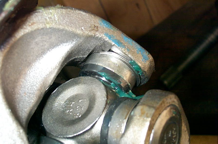
 |
When everything is back together (except the drive flanges), rotate the shaft in place and check to make sure the U-joint turns freely between the knuckle and end forging, that there is no binding or interference. Do this throughout the steering range of the knuckles. Ensure the grease fitting is accessable and not interfering. |
||||||||||||||||||||||||||||||||||||||||||
 |
The last part of the assembly is to install the new warn 35 Spline Drive Flanges. First, take the 2 "wear washers" (the small flat washers, not to be confused with the stub shaft snap rings)... |
||||||||||||||||||||||||||||||||||||||||||
 |
...and place them over the stub shaft. | ||||||||||||||||||||||||||||||||||||||||||
 |
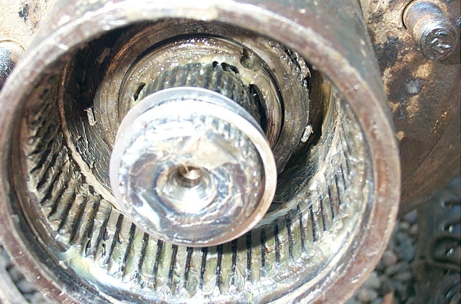
Then slide the drive gear in place over the stub axle. You may need to rotate the axles slightly to get the stub shaft splines, drive flange, and hub splines all lined up. | ||||||||||||||||||||||||||||||||||||||||||
 |
Fully installed it looks like this. | ||||||||||||||||||||||||||||||||||||||||||
 |
Next place the stub shaft snap ring over the end of the stub shaft and into the groove. | ||||||||||||||||||||||||||||||||||||||||||
 |
Then place the drive flange cap retention plate in the hub... | ||||||||||||||||||||||||||||||||||||||||||
 |
... and install the big outer snap ring. | ||||||||||||||||||||||||||||||||||||||||||
 |
The last thing to do is tighten down the #8 Torx screws that are pre-impregnated with thread locker. | ||||||||||||||||||||||||||||||||||||||||||
 |
And you're done!!! | ||||||||||||||||||||||||||||||||||||||||||
 |
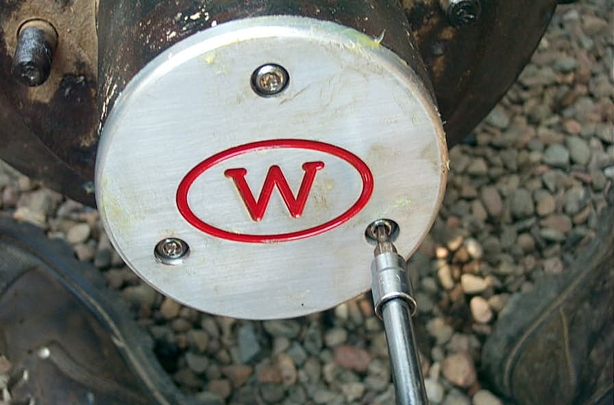
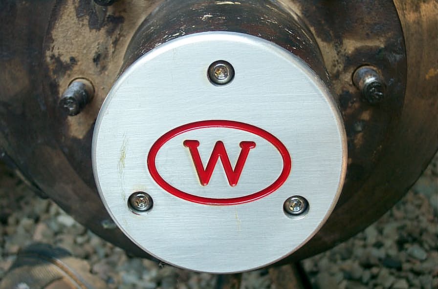
It's AWESOME how much less protrudes from the hub with the 35 spline drive flanges compared to lockout hubs. And of course, having the biggest 35 spline axles throughout brings a lot of peace of mind... |
||||||||||||||||||||||||||||||||||||||||||
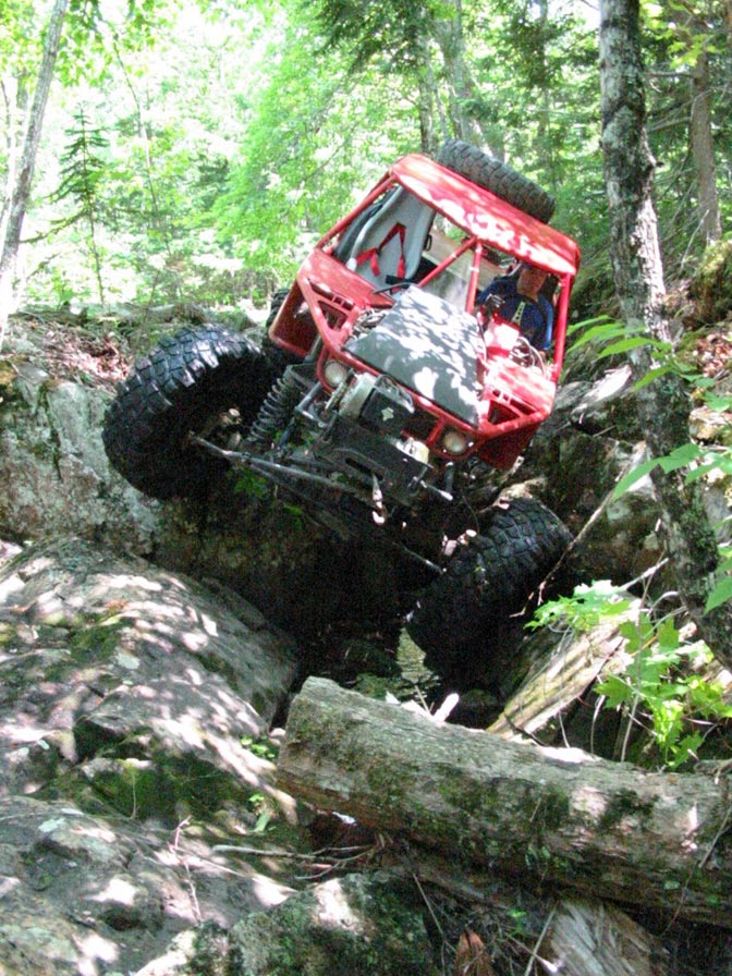
Part 6 - Testing...And that peace of mind is great to have when you like to go out and Fully Get It like I do. Here are some shots and a short video clip of my first 2 runs since the install. From high torque, 110:1, crossed up, full-lock, bound-up rock crawling, to 6000 rpm full-throttle assaults on slick, muddy, rocky hill climbs - I did my best to break something...but everything has held up extremely well so far, and I really enjoy the extra clearance with the drive flanges tight to the hub body. Check out the pics. |
|||||||||||||||||||||||||||||||||||||||||||
 |
Full lock, and throttling through a tight spot. Murder on joints and shafts...but not a problem for me now! | ||||||||||||||||||||||||||||||||||||||||||
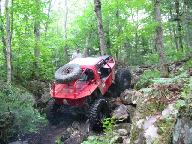 |
A tough rocky climb - tried several ways - from crawling to throttling. | ||||||||||||||||||||||||||||||||||||||||||
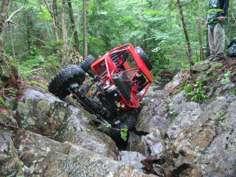 |
Another brutal, low-low gear, caught-in-a-crack, rock crawling spot. I *may* have needed a spot of help to get out...but I didn't break, and I gave it hell trying! :-) | ||||||||||||||||||||||||||||||||||||||||||
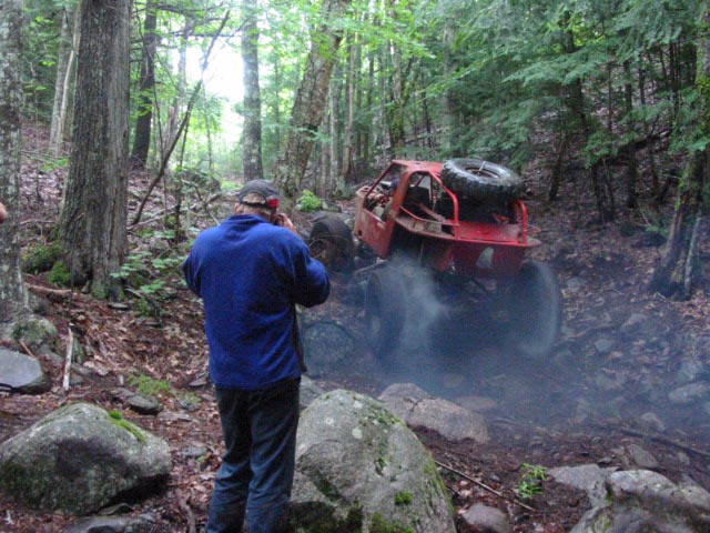 |
Check out the smoking tires.....I love being able to attack things with confidence when required. that's why, as I mentioned way back in the beginning, I don't believe in designing in a weak link...let my courage be the weak link! | ||||||||||||||||||||||||||||||||||||||||||
|
|||||||||||||||||||||||||||||||||||||||||||
 |
Sources: 4wdfactory.com(512) 759-6267 |
|