 |
Engine Oiling By Bill "BillaVista" Ansell |
IntroductionEngine oil and oiling - welcome to one hell of a complicated subject! Let me state right now - I do not claim to know the truth, the whole truth, and nothing but the truth about engine oil and oiling. The reason is, it's actually a very complicated topic. In fact, I'd venture to say that the physics and chemistry of engine oil and lubrication is THE most complicated topic relating to your car or truck. Heck - even the experts don't yet understand or agree on all of it. |
 |
||||||||||||||||||||||||||||||||||||||||||||||||||||||||||||||||||||||||||||||||||||||||||||||||||||||||||||||||||||||||||||||||||||||||||||||||||||||||||||||||||||||||||||||||||||||||||||||||||||
For example, from SAE paper J357 "Physical and Chemical Properties of Engine Oils": High-shear-rate viscosity measured at 150 °C and reported in mPa·s (centipoise) is widely accepted as a rheological parameter which is relevant to high-temperature engine performance. In particular, it is generally believed to be indicative of the effective oil viscosity in high-shear components of an internal combustion engine (for example, within the journal bearings and between the rings and cylinder walls) under severe operating conditions. The bold yellow text in that statement are some pretty qualifying statements that indicate that there is not complete agreement among the experts. And those are some dudes with some really big heads! They even have really big names. For example - a "tribologist" is a scientist or engineer that studies the science of wear and friction. So what is the average enthusiast like you or I supposed to do? . What I did was read a ton of papers and articles to form a basic understanding of the principles involved so that I would be reasonably educated on the topic, allowing me to form at least semi-educated opinions when deciding what was best for my engine. I also built my own engine oiling system for my LS2 by assembling a collection of quality aftermarket parts including cooler, accumulator, remote filter, and custom plumbing. So that's what I'm going to document here in hopes that you may find it useful. The bottom line is - I do not, in any way, claim to be an expert in this field, and some of what follows will unavoidably be opinion or educated guess. To paraphrase a friend of mine, "Oil...It's that damn complicated!" So with that said, I'm first going to tackle an introduction to engine oil; and then finish with a look at the components that make up a quality oiling system - from pan to pump to accumulator and back.
OilWhat is oil?Engine oil is not just a liquid - it's actually a "dilute polymer solution". What the heck does that mean? A polymer is a chemical compound made up of a long chain of repeating molecules. It means oil is a whole bunch of different chemical components and molecules combined is specific ways to create a sort of "liquid machine". Think of it like a whole bunch of tiny, microscopic molecular machines combined in long links like a bicycle chain. Why is it so complicated?The science of engine oiling is, in part, complicated because oil has so many important functions in the modern internal combustion engine. Ask someone what oil is for, and they usually get one or two from the list, but rarely all. The purpose of engine oil is to:
Basic oil compositionIn order to be able to do all that, over a wide range of operating conditions (esp. at different temperatures), the oil you put in your engine is made from about 80% base oil and 20% additives. In the case of so-called "dino oils" the base stock is refined from crude oil extracted from the ground. In the case of synthetic oils, the base stock is chemically synthesized. Base stocks typically have molecular weights ranging from 300-600, whereas additives such as viscosity modifiers are very large polymers with molecular weights of 10,000 or more. Why is it important?Well, the obvious answer can be gleaned from looking at the above list of jobs the oil has. We wouldn't want to be lacking any of these in our engine. In addition, and particularly important in high performance applications, using the proper oil with the correct physical and chemical properties for the application ( matched to the engine and operating conditions) minimizes friction and thus increases available power output and minimizes engine wear. The specific physical and chemical properties come from the "formulation" of the oil - that is, from the specific combination of base stocks and additives. Base StocksA variety of different processes are used in the manufacture of base stocks for engine oils. They include:
We're not going to go into these methods and talk about hydrocracking, converting aromatics to napthenes, isomerization, and the rest of the organic chemistry involved. While it may be interesting to some - it doesn't really mean much to we users because you can't usually buy an oil based on the method by which the base stock was refined. Additive PackagesIt is far more important for us to understand a little about additives in the oil - why they are required and what they do, because it is possible to do your research and buy certain oils based on their additive packages. This is true to a point, however people often way over-state the importance of a single additive, without realizing that in the complex polymeric machine that is modern oil - it is the combination, the whole package, that is important (and not just "buy brand X because it has a lot of additive Y in it"). A lubricant additive is a material designed to enhance the performance properties of the base stock or to impart to the base stock properties that do not naturally exist within the base stock. These additive agents are used at concentration levels ranging from several parts per million to 10 percent by volume or more. Generally, additives are materials that have been chemically synthesized to provide the desired performance features but some are naturally occurring materials that have undergone only minor modifications. Additives can carry out their task of enhancing or imparting new properties to an oil in one of three ways:
Some additives possess multifunctional properties. It is an important consideration for oil manufacturers to use additives that are compatible with each other as well as with the base stock. From the consumer's perspective, it is equally important to use engine lubrication products that are compatible. The best way to achieve this is to:
DefinitionsCLOUD POINT POUR POINT ViscosityThe most critical of an oil's properties is its viscosity, and how that viscosity varies with temperature, shear rate and pressure. The variation of lubricant viscosity with temperature, shear rate, and pressure is crucial to how the lubricant performs in an engine. These properties are important in controlling oil film thickness and friction in the bearings, the piston assembly, and the valvetrain. (Shear rate is the stress or force put on the oil molecules by sliding metal surfaces that tends to shear or break-up the molecular chains.) The goal is to maintain correct/optimum oil film thickness (to separate the moving parts in the engine) while minimizing engine friction and therefore power losses. The oil must be able to do this under widely varying conditions of temperature and rpm/load, while remaining pumpable at low temperatures when cranking/starting the engine. No small task! While the physical and chemical properties of an oil at operating temperatures (such as viscosity) are not related to oil
performance in a simple way, these individual properties are meaningful and are related to the oil's ability to Viscosity is defined as the internal resistance to flow of any fluid. It is commonly thought of as how "thick" or "thin" the fluid is, or how "pourable" it is. For example, at room temperature, molasses has a very high viscosity, while water has a fairly low viscosity. Viscosity is expressed as: Dynamic Viscosity = ( Force / Sheared Area) / (Velocity / Film Thickness) = Sheer Stress / Shear Rate The unit of measure for dynamic viscosity is the millipascal second (mPa·s), although the centipoise (cP) is Oils that exhibit a viscosity which varies with changing shear rates in this equation are known as “non- Almost any oil you put in your engine is going to be a non-Newtonian oil. Another way you may see viscosity expressed is by Kinematic Viscosity. Kinematic Viscosity is determined by measurement using a method where the result is directly affected by the density of the liquid at the temperature the measurement was made. This method is easier than determining all the variables needed for the equation to calculate dynamic viscosity (above), but has the disadvantage that results are less directly comparable because of the effect of density. As such, strictly speaking it is best to either measure dynamic viscosity or to measure kinematic viscosity and density of the liquid at the temperature of interest and convert kinematic viscosity to dynamic viscosity using the equation: Kinematic Viscosity= Dynamic Viscosity / Density of Liquid The unit of measurement for kinematic viscosity is the millimetre squared per second (mm^2/s), although the centistroke (cSt) is also commonly used. One mm^2/s equals 1 cSt. What does all this mean? It means that the viscosity of an engine oil changes with both temperature and with the load we place on it in the engine (pressure and shear rate). Since temperature, pressure and and shear rate can all vary widely in the engine (for example engine oil may be at 30°F when the engine is cold and first started, but rise to 300°F under hard use), we need a way to both identify and control (as much as possible) the viscosity of the oil under different conditions, because the viscosity plays such a huge role in achieving our goal, which we said was to maintain correct/optimum oil film thickness (to separate the key moving parts in the engine) while minimizing engine friction and therefore power losses. For an engine oil, the viscosity must be sufficiently high so that the phenomenon of hydrodynamic lubrication can occur. This is where the flow of the oil forces the bearing surface to ride on a thin film of oil and, thus, protect the lubricated surface from wear. Neither identifying the viscosity of an oil under different conditions nor controlling it is a simple task. Before we move on, let's have a look at a simplified chart of some typical engine oil viscosities in cSt to give us some perspective:
Flow & Oil PressureWhat does all this complicated talk of viscosity translate to in the real world? The viscosity of the oil directly affects its pressure and flow as it is pumped around the engine to do its many jobs. Time to dispel a huge misnomer about engine oil and lubrication. Many folks mistakenly believe that oil pressure is the be-all end-all of engine lubrication - and understandably - as we have an oil pressure gauge after all. Unfortunately, this is not quite true. It is in fact the flow of oil that lubricates, cools, and cleans the engine. Adequate pressure to create this required flow is vital, to be sure. But do not be mislead into thinking that pressure is everything and the higher the oil pressure the better. In fact, pressure and flow are inversely proportional - as one goes up, the other must go down. So, for example, if you were to use a very thick (viscous) oil in your engine - pressure would go way up, but flow would go way down (it is, in fact, the resistance to the flow of the thick, viscous oil that causes the pressure to go up). The reason we have an oil pressure gauge is that it is much easier to measure oil pressure than oil flow. So - adequate pressure is critical - but too much can be as bad as too little if it's an indication that the oil is too thick to flow adequately for lubrication and cooling. Imagine you used 90W/140 gear oil in your engine - a very thick, viscous oil. You'd have tremendous oil pressure - for a short while, anyway! But the oil would not flow enough to cool and lubricate and the engine would soon be destroyed. We'll return to this topic a little later when we discuss selecting and engine oil, but for now, keep in mind that oil pressure is vital, but not at the expense of flow - and that too much pressure is often a result of too little flow - more is not always better when it comes to oil pressure! The golden rule for almost any engine is 10 psi oil pressure per 1000 RPM. Viscosity VariationViscosity decreases rapidly with increasing temperature. For most oils, the relationship between viscosity and temperature can be approximated by the empirical relationship in the following equation: loglog(kinematic viscosity+ 0.7 ) =A+B (log absolute temperature) where: This relationship, which is an approximation of the MacCoull, Walther, Wright equation, forms the basis for The Viscosity Index is calculated as such:
I warned you it was a complicated topic - didn't I?! Let's try and simplify things a bit. For engine oils, a relatively small change in viscosity with temperature (high VI) is desirable to provide a wider range of operating temperatures over which a given oil will provide satisfactory lubrication. At low temperatures, a relatively low viscosity oil is desirable to permit adequate cranking speed during starting, and then adequate flow to the oil pump and the entire engine oiling system after starting. At high temperatures in a running engine, the oil viscosity must be high enough to maintain adequate film thickness between rotating or rubbing parts to minimize wear. Using a higher viscosity oil generally reduces oil consumption (past piston rings and valve guides) and blowby, but increases friction associated with oil film shearing in the piston/piston ring cylinder wall interface and in the bearings. To extend the upper temperature limit at which an oil will still provide satisfactory lubrication, polymeric additives, called Viscosity Index (VI) improvers, are widely used. Engine oils properly formulated with VI improvers generally contain lower viscosity base stocks which provide better low temperature cranking/starting and pumpability properties. As the oil temperature increases, the viscosity of the oil containing a VI improver decreases more slowly than the same oil without a VI improper, thus increasing the VI. The result is an oil that can give good starting/pumping response and is also effective in providing a more viscous oil film at operating temperatures than could be obtained with a single grade oil providing equivalent startability at low temperatures. Oils containing a polymeric VI improver exhibit a decrease in viscosity as the shear rate or stress is increased. Because the viscosity of such oils depends on shear stress, they are called “non-Newtonian oils.” Such change generally lasts only as long as the oil is operated under such high shear stress. When the shear stress is relieved, the oil reverts to its previous viscosity. This reversible decrease in viscosity due to shear is called “temporary shear (or viscosity) loss.” When certain critically high shear stresses are imposed on a VI improver in oil solution, the viscosity contribution of the VI improper to both low and high shear rate viscosity can be permanently reduced. This nonreversible reduction in viscosity is called “permanent shear (or viscosity) loss.” The magnitude of these temporary and permanent losses is dependent on the type and molecular weight of the VI improver used, as well as the actual service conditions. In other words - VI Improvers can wear out. Note that, in addition to VI Improvers, other chemical additives, fuel dilution, contaminants from within and outside of the engine, wax in the oil, oil oxidation, volatilization, and many other materials found in or added to the oil affect the viscosity. This is, of course, one of the reasons why even the best oils need to be changed regularly. The use of VI Improvers is what gives us the "multi-grade" oils we are so used to today. Sadly, no oil is labelled with its VI, and the SAE labelling system in use today is actually a fairly broad system of classification which, if not well understood, can cause a lot of confusion and misunderstanding. Let's have a look at it now. SAE Standard Oil Labelling System.So what does the labelling on the can, like "5W30", really mean and what does it tell us? First and foremost, we must understand that the labelling on an oil can IS NOT telling us the viscosity of the oil - it is telling us the "Grade" of the oil according to the methods published by the SAE. That is, the SAE grade is a classification or grouping of oils based on viscosity, but not a measurement or statement of the oil's actual viscosity. In other words - the actual viscosity of oils of the same grade can vary - and sometimes by quite a bit. Let's take a step back first, and look at things from the engine designer's perspective. OK, if we refer back to our first chart of typical viscosities, we see that a straight 30 weight oil has a viscosity of about 10 cSt at 100°C. Simple then - the designer builds the engine and simply tells the user to use 30 weight oil. Done. What's all the fuss? Not so fast grasshopper - remember all the things we just discussed that affect viscosity - chiefly temperature? Our simple plan of "just use 30" would work fine if the engine and oil were always at a constant 100°C, and if it operated such that there were no changes in shear rate and pressure, nor any contaminants ever introduced. Alas, we know this is not the case. In the real world, we must contend with all these things, the biggest being temperature. As we discussed, the viscosity of oil varies with its temperature. A straight "30”weight" oil may have the desired viscosity at 100°C (212°F), but look how it varies with temperature:
Clearly, as the temperature varies from the designed operating temperature the oil become unsuitable. As the engine heats up under hard use, the oil thins unacceptably and will not lubricate sufficiently. As the engine cools down to ambient temperature, the oil thickens unacceptably and will neither lubricate sufficiently, nor pump and flow sufficiently. Straight 30 weight oil has a very low Viscosity Index (VI). The Solution? While not perfect, the solution to this dilemma lies in the use of so-called "multi-grade" oils that do not exhibit the same change in viscosity with temperature as the good old straight 30 weight oil does. This is achieved either by adding VI improvers to mineral-base oils, or by the actual molecular synthesis of synthetic-base oils. The idea being to create an oil that neither thickens too much when cooled, nor thins too much when heated - but rather remains as close as possible to the ideal viscosity throughout the range of temperatures in which it is to be used. DO NOT confuse multi-grade with multi-viscosity. Remember, the goal is to produce an oil that has a near-constant viscosity regardless of temperature (as much as is possible). Oils are assigned grades based on a number of criteria. In order to understand multi-grade oils, we must first understand single-grade oil classifications. Single Grade OilsThere are two different groups or series of grades used by the SAE to classify engine oils. The difference between the series is the type of testing done on the oil. The low-temperature-use or "W" grade oils:In one series, the grade an oil is assigned is based on maximum low-temperature cranking viscosity, maximum low-temperature pumping viscosity, and a minimum kinematic viscosity at 100 °C. Oils in this series are identified by a number (often referred to as the "weight" of the oil") followed by the letter "W" (e.g. "10W"). Many folks believe the W stands for "winter use", presumably because these oils go though low-temperature testing. In fact, the W doesn't stand for "winter", but is just the method chosen to identify the series of oil grades that include low-temperature (below-freezing) testing - so it's easy to see why the connection was made between W and "winter".
Note that the figures in the table are LIMITS, either minimum or maximum, as indicated, that an oil must meet in order to be classified into that grade. They are not actual SPECIFIC guaranteed specifications. This is one reason why the performance of identicaly classified (and therefore labelled) oils can vary. Column 1, Low-Temperature Cranking Viscosity, correlates with the ability of an engine to start at low temperatures. Thus, for example, if you plan to start your engine when temperatures are colder than –25°C, you would need to choose a 5W or 0W grade oil. Column 2, Low-Temperature Pumping Viscosity, is a measure of an oil's ability to flow to the engine oil pump and provide adequate oil flow during the initial stages of operation. Don't ask me why the temperatures don't correlate between columns 1 and 2 - I don't know and it doesn't make sense to me why not - take for example the criteria for a 10W grade oil - it's hardly likely that you'd want to start an engine at only –25°C but run it at –30°C. (This is actually a sneak-peek at one of the conclusion I shall eventually draw - that the SAE labelling on the can doesn't really tell the average user a whole heck of a lot!) Column 3, Low-Shear-Rate
Kinematic
Viscosity, has been shown to be related to certain forms of oil consumption (e.g. if kinematic viscosity is too low, the engine may suffer excessive oil consumption past the rings) and
have been traditionally used as a guide in selecting oil viscosity for use under normal engine operating Obviously, since the criteria in the three columns are maximums and minimums, it is possible for an oil's actual test results to satisfy the requirements of more than one W grade. In labelling a W grade, only the lowest W grade satisfied may be referred to on the label. Thus, an oil meeting the requirements for SAE grades 10W, 15W, 20W, and 25W, must be referred to as an SAE 10W grade oil. An oil must meet the pumping requirements of the lowest W grade satisfied by the cranking viscosity. If If the kinematic viscosity at 100°C of an oil does not meet the requirements of the lowest W grade satisfied by the The high-temperature-use grade oils:In the second series, the grades are defined by a number only. In order to be assigned one of these grades, an oil must meet certain different criteria. Oils are assigned one of these grades based on their meeting a set of minimum and maximum kinematic viscosities at 100 °C, and a minimum high-shear-rate viscosity at 150 °C.
Columns 1 & 2, Low-Shear-Rate Kinematic Viscosity, as for the W grade oils, has been shown to be related to certain forms of oil consumption and have been traditionally used as a guide in selecting oil viscosity for use under normal engine operating temperatures. Column 3, High-Shear-Rate Viscosity measured at 150 °C, is widely accepted as a rheological parameter which is relevant to high-temperature engine performance. In particular, it is generally believed to be indicative of the effective oil viscosity in high-shear components of an internal combustion engine (for example, within the journal bearings and between the rings and cylinder walls) under severe operating conditions. While the specific temperature and shear rate conditions experienced by an oil in a particular application depend on mechanical design and operating parameters, the measurement conditions specified are representative of a wide range of engine operating conditions.To insure that polymer-containing oils do not create a situation in which the viscosity of the oil decreases to less than a specified limit, minimum values of high-shear-rate viscosity are assigned to each of the non-W viscosity grades as per column 3. Multi-Grade OilsSo, let's return to our theoretical engine that we have designed to run at a water and oil temperature of approximately 100°C (212°F) and that requires an oil that has a kinematic viscosity of 10 cSt at this temperature. Let's assume further that we need to be able to start and run this engine at temperatures down to -30°C. Examining the SAE grade tables shows us that no single-grade SAE oil, whether W or non-W, will satisfy our requirements - the same conclusion we reached when we looked at the properties of straight 30 grade oil. Enter the multi-grade oil. In order to be classified as a multi-grade oil, and be assigned both a low and high-temperature SAE grade, an oil must meet the low-temperature cranking and pumping viscosity requirements of one of the W grades and all of the requirements of one of the non-W grades. Depending on which combination of grades it meets, and subject to the requirement that only the lowest W grade satisfied may be referred to on the label, an oil may be assigned a multi-grade designation, such as 10W-30. In this case, the the W grade must precede the non-W grade, and the two grades must be separated by a hyphen. If this is the case, it means we have an oil that satisfies both low-temperature performance requirements as well as high-temperature, high-shear requirements. Many folks will refer to a multi-grade oil such as 10W-30 as an oil that "acts like a 10-weight oil when cold, and then acts like a 30-weight oil when hot". By looking at the tables above, we can see that this is not strictly accurate. All it means is that any oil so labelled meets the requirements of both a 10W oil and a 30 oil. The precise change of that oil's viscosity with temperature can only be achieved by plotting the Viscosity Index - something few if any users are ever going to do. That said, it's not entirely inaccurate to think of a multi-grade oil in this manner. What we can say for certain is that a multi-grade oil will do a much better job of being thin enough at low or cold start-up temperatures to crank, pump, and flow well, while remaining thick enough at high temperatures to lubricate properly and provide the necessary hydrodynamic separation of metal parts. By combining the requirements of the W and non-W grades into a single table it is easy to compile a table of requirements for any multi-grade oil. Here are some of the more popular multi-grades available on the market:
Note: A special situation exists regarding the SAE 40 grade. Historically, SAE 0W-40, 5W-40, and 10W-40 oils have been used primarily in light-duty engines. These multigrade SAE 40 oils must meet a minimum high-temperature, high-shear-rate viscosity limit of 2.9 mPa·s. In contrast, SAE 15W-40, 20W-40, 25W-40, and 40 oils have typically been used in heavy-duty engines. The manufacturers of such engines have required high-shear-rate viscosity limits consistent with good engine durability in high-load, severe service applications. Thus, SAE 15W-40, 20W-40, 25W-40, and single-grade 40 oils must meet a minimum high-temperature, high-shear-rate viscosity limit of 3.7 mPa·s. Of course, you cannot, and should not, use this table as the only method to selecting a grade of engine oil for your application. There is a great deal that isn't shown in the table - all the variables we've already discussed. All it shows is the criteria that must be met for an oil to be assigned an SAE grade. For example, if you look at the table, you could conclude that the only difference between a 5W-30 and a 10W-30 is that the 5W-30 has better cold start capabilities. While this is certainly true, it isn't the whole story. Consider that for both, the Kinematic Viscosity requirements at 100°C (normal operating temperature) are a range - from 9.3 - 12.5 cSt. It may be reasonable to assume that the 5W-30 may have a lower actual viscosity at this temperature, and probably at all temperatures below this. When we recall that manufacturer's generally recommend oils based on the required viscosity at operating temperature, and we recall that all oils will be thicker than this at start-up (even if ambient temperatures are well above freezing) we may decide that 5W-30 is a better choice than 10W-30, even if we have no intention of operating at below-freezing temperatures, as it's viscosity will be less than the 10W-30 and therefore closer to the optimum viscosity, even as the engine is warming up to normal temp. Mineral vs SyntheticThe method by which mineral and synthetic oils achieve multi-grade capability is different. Remember, multi-grade doesn't mean multi-viscosity - quite the opposite, it means the greatest possible ability to maintain a constant viscosity with changing temperature. Mineral oils achieve this performance by adding VI Improvers that prevent the oil from thinning too much as temperatures increase. For example, a 10W-30 multi-grade mineral-based oil is made from a 10 weight oil and has VI improvers added to prevent it from thinning as much as a straight 10-weight oil when the engine reaches operating temp so that it has the properties of a 30 weight oil when hot. In contrast, a 10W-30 multi-grade synthetic oil is based on a 30 weight oil. Because of this, no VI improver is needed as the oil will have the correct desired viscosity in an engine at normal operating temperature of 100°C (212°F). The difference is, because of the way a synthetic oil is manufactured using custom molecular structures, a synthetic oil can be produced that meets the requirements of a 10 weight oil when cold while also meeting the requirements of a 30 weight oil when hot. And since they are able to achieve this without VI improver additives, there are no additives to wear out as the oil is used. This is one of the advantages of a synthetic oil. By design they are less thick at start-up temperatures than mineral-based oils - even between oils with the same SAE grade. This is one of the limitations of the SAE grading system - we can't tell from it that identically labelled oils can have dramatically different properties, including viscosity. However, much research, testing, and comparisons have been done and we know conclusively that a 10W-30 synthetic oil will have lower actual viscosity and better pourability, pumpability, and lubricating ability at cold temperatures than an identically graded 10W-30 mineral-based oil - even though they both qualify for the same SAE grading and labelling. Without getting into any more complicated chemistry, other properties of synthetic oil make it a superior choice for engine lubrication, resulting in less wear, less friction, cooler running, and better power and economy. It is the all-round better choice except when breaking in a newly built or re-built engine where its superior lubricating properties can actually interfere with proper bedding in of the piston rings and cylinder. But the main advantage that the synthetic has over the mineral based oil is the ability to lubricate at startup. Synthetics have lower viscosities and much better fluidity as the temperature drops (regrdless of their labelled grade). If temperatures get cold enough, mineral based oils eventually become unpourable and unpumpable - whereas synthetics can be used at much lower temperatures - this is why there are no 0W-xx graded mineral-based oils. Engine vs Gear OilsBefore we leave the topic of oil labelling and SAE grades, let's just make one other point. Not all oils use the same grade structure. For example, gear oils use a different scale altogether from engine oils, and so the numbers are not directly comparable, even though they look very similar. For example, a 75W-90 gear oil has about the same viscosity as a 10W-40 or 10W-50 engine oil! The following table offers a rough comparison of different oil grades.
So - at this point you are probably about as sick of reading about oil viscosity as I am of writing about it. And yet we haven't come to any iron-clad conclusions or solid rules on choosing engine oil viscosity. About the only thing that we know for sure is that the detailed science and chemistry involved is WAY complicated. This may lead to the one best conclusion we can draw being: "deviate from the manufacturer's or engine-builder's recommendations with caution." Hopefully, what we have accomplished though is to at least have increased our understanding of the subject so that we are better able to evaluate further research we do or advice we are offered. For example, if you read on some forum some piece of advice or opinion about what to use - now you can evaluate that from at least a semi-educated perspective. This might just be the most useful lesson to take away from all this. Choosing an OilOK, so we have learned that selection of the optimum oil:
There are also other properties and qualities the optimum oil must have, with most of these related to the additive packages used in the oil's formulation. For example, oil must also have good anti-foaming performance (esp. in high rpm applications) because aerated oil can cause problems with hydraulic actuation (for example, in hydraulically activated valve lifters) - like air in the brakes. Also, aerated oils can cause cavitation damage in bearings. However, the bottom line is, none of the the physical and chemical tests described in any of the many ASTM, API, or SAE documents listed in the references section can be used effectively for accurately defining performance characteristics at operating loads and temperatures. Only actual performance evaluations in special laboratory engines or in actual field tests will define the capabilities of an engine oil. What that means is that reading an oil's specification, examining the formulation, pouring over the list of additives, arguing over the brand or type - none of these things will actually determine how an oil will perform in any particular application. Only laboratory testing, dyno testing, and real-world testing can determine this Although laboratory engine tests like those described in SAE J304 are necessary and valuable aids to engine oil development and evaluation, they have limitations. In many instances, the final proof-of-performance is established by field tests of the oil in actual vehicle service. Although oil performance in the engine is related to base stock and additive composition, it is often difficult to assign a specific aspect of such performance totally to the use of a specific additive or base stock. Part of the reason is that some of the physical and chemical properties of the oil overlap in their influences on engine performance and durability and it is presently difficult to directly and unambiguously attribute such effects to either the chemical or the physical properties of the oil. Progress in developing this level of understanding is being made. Some of these performance characteristics What does this mean for us? It means that the truly dedicated looking for every ounce of performance are in for a LOT of research, testing, and evaluation. A good place to start is by reading the papers listed in the reference section at the end of this article, contacting and working with oil manufacturers and engine builders, and developing and performing relevant performance tests to be followed by analysis of used oil samples. That's a lot of work. Most of us will never have the resources to do this. So where does that leave the rest of us? Fortunately, not hung out to dry. The lubrication requirements for modern engines are extremely complex. Current engine oils
are the result of extensive research and development aimed at meeting these requirements. Lubricant and additive
manufacturers, engine manufacturer organizations, the One of the most common and familiar methods for engine manufacturer's to specify suitable oils for their engines is by use of the API Engine Oil Licensing and Certification System. This is a system of engine oil performance categories and classifications developed through the efforts of the Alliance of Automobile Manufacturers (AAM), American Petroleum Institute (API), the American Society for Testing and Materials (ASTM), the Engine Manufacturers Association (EMA), International Lubricant Standardization and Approval committee (ILSAC) and SAE. It provides a communications tool for both engine manufacturers and oil marketers to describe a complex series of performance specifications to the user through a simple designation of several letters or symbols. This simplifies the oil marketer’s job of communicating the applications for which his oil is suitable by using the same designations on his containers. More importantly, the consumer can easily link the engine manufacturer’s recommendation with the information on the oil marketer’s label to assist him in selecting the proper oil for his engine. The system embodies several different types of classifications including the API “S” series which describes engine oil standards primarily for gasoline engine service, the API “C” series which defines standards for diesel engines, and the ILSAC GF Series, “Minimum Performance Standard for Passenger Car Engine Oils.” The latest "S" series specification is "SM". This can be found on the back of an oil bottle or can in the familiar circular symbol, like this ("SJ" specification shown):
For those interested in further details of the API Engine Oil Licensing and Certification System, I recommend reading SAE J183 "Engine Oil Performance and Engine Service Classification (Other than “Energy Conserving”)" and SAE 1423 "Classification of Energy Conserving Engine Oil for Passenger Cars, Vans, Sport Utility Vehicles, and Light-Duty Trucks" On the whole, engine oil performance improves with each successive specification in the series - for example, SH oils outperform SG oils. However, in some cases, engine oils with newer classifications may not always provide satisfactory performance where older classifications are recommended. A recent example I have read about but don't have a lot of experience with is the recent reduction of ZDDP levels in the change from SL to SM oils. Basically, the most common additive package for motor oils designed to reduce wear (anti-wear) is a combination of zinc and phosphorous that is commonly called ZDDP. When ZDDP burns it produces ash that tends to be detrimental to catalytic converters and other emissions equipment, so levels of it have been reduced in SM oils, and replaced with other no-ash antioxidants. There's a whole lot of people out there pouring over spec sheets and how many parts per million of ZDDP there are in various oils - some claiming SM oils are the devil. As I said - I don't have a lot of personal experience with this topic - but a lot of what I have read doesn't seem to be backed up by a whole lot of solid science. Most of all, remember that:
Rules of ThumbAfter all this, I hope you weren't expecting me to be able to tell you exactly what the best oil to run in your engine is? About the best I can do is offer you my opinions and thoughts on the matter in the form of some semi-educated rules-of-thumb.
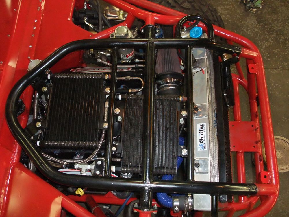
My LS2 Oiling SystemThe stock GM Gen III/IV oiling system routing goes like this: Oil pan – pickup tube – crank driven gerotor pump – main oil galley (driver’s side of block) – oil filter – up rear driver’s side of block – main feed galley (runs through the lifter bodies) – up to top of engine through pushrod passages – drains back to pan through drain-back passages throughout the heads and block – oil pan. It's a very well engineered system, but for hardcore use it can stand to be upgraded a bit. So here's the what and why of what I did. Although what follows features my LS2, it can be directly applied to any GM Gen III/IV, and many other engines as well. Oil PanBeing a Corvette motor, the first thing I did was swap the relatively shallow Corvette oil pan for a Camaro LS1 oil pan. The LS1 oil pan has a unique shape and is made from lightweight cast aluminum. It features extended sumps that contain additional oil to ensure a good supply of oil to the pick-up tube. Compared to older small-block pans, the LS1 pan has better sealing and greater structural integrity. The Gen III/IV motors also have a large flat surface to which the oil pan is bolted, eliminating curves and corners that are hard to seal. The specially shaped oil pan is also a structural member, enhancing overall engine rigidity. |
|||||||||||||||||||||||||||||||||||||||||||||||||||||||||||||||||||||||||||||||||||||||||||||||||||||||||||||||||||||||||||||||||||||||||||||||||||||||||||||||||||||||||||||||||||||||||||||||||||||
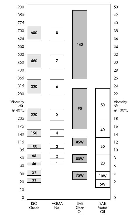
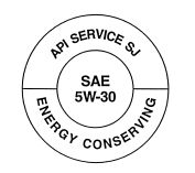
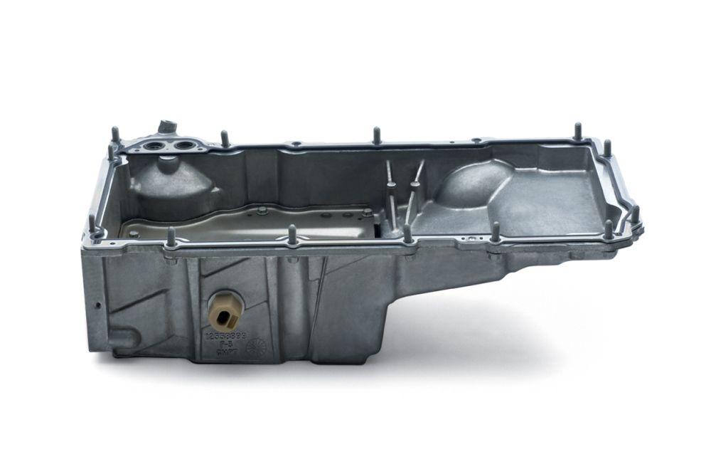 Photo © GM Corp. Photo © GM Corp. |
LS1 Camaro cast aluminum oil pan. | |
There are aftermarket stamped-steel or welded oil pans available for the LS motors that are quite popular with some folks. They are built with additional baffles or trap doors to help keep the oil from sloshing around and keep it close to the pickup. I took a good look at these before going with the LS1 pan, but ultimately decided against one for the following reasons:
Altogether, I personally am just happier with the cast aluminum pan. For reference, here are the depths of some different Gen III/IV oil pans:
Note, an F-body (Camaro/Firebird) LS1 oil pan makes the bottom of the oil pan level with the bottom of a TH400 transmission pan. When swapping an oil pan you need the pan, the dipstick and tube, the pickup tube, and the gasket. Oil PumpGen III/IV motors use a high-efficiency Gerotor oil pump, driven off the front of the crankshaft, eliminating the old cam-driven design. |
||
5.jpg) Photo © GM Corp. |
Gerotor oil pump, disassembled view. | |
| Because of their design, these pumps are more efficient, reliable, and better performing than the old-style oil pumps. However, if you are planning on running your engine oil outside the engine, as I do, for a cooler, remote filter, or accumulator it is good insurance to invest in a quality modified or aftermarket high-volume oil pump. | ||
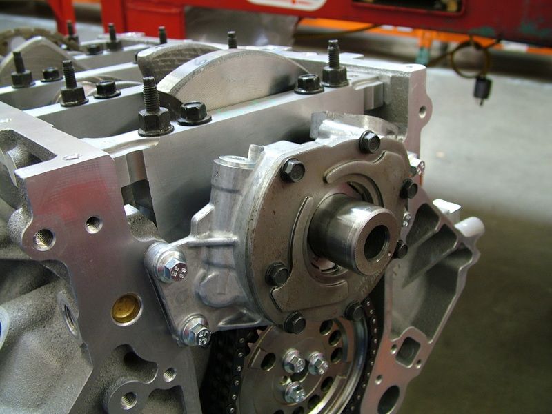 |
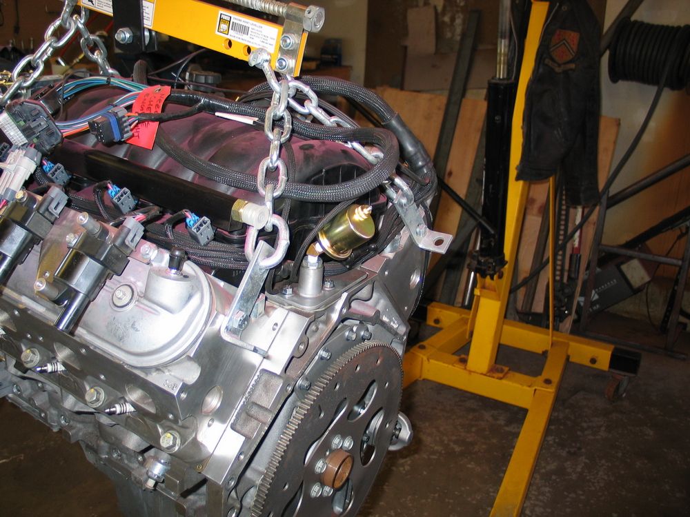
Turn Key Engine Supply built my LS2 with this high-flow oil pump that provides approximately 30% more volume than the stock LS2 oil pump. In this pic you can see how it is driven off the front of the crankshaft. |
|
Remote FilterModern stock automotive engine filtration systems are actually pretty good. Unlike years ago, most systems employing the common "spin-on" type oil filter are full-flow systems - meaning all of the oil is filtered all the time - it all passes through the filter on each circuit of the system. (Years ago, in early "bypass" systems, not all of the oil passed through the filter all the time. Most of the oil bypassed the filter and was pumped straight from the tank to the engine oil galleys. Only some of the oil passed through the filter via a second flow path in parallel with the first, and therefore it took some time to filter all the oil). Stock-style spin-on filters also incorporate a different kind of bypass (not to be confused with the old-style bypass system). In this case, the bypass is either incorporated into the filter unit, or as part of the oil filter housing on the engine, and is pressure activated. Should the filter become extremely clogged, the pressure differential across the filter would rise sharply, causing the bypass valve to open, and the oil to bypass the filter. The theory is - lubrication with unfiltered oil is better than none at all. Other advantages to the popular "spin-on" filter include reduced cost and greater convenience since they are entirely disposable units that need only be removed and discarded when changed. |
||
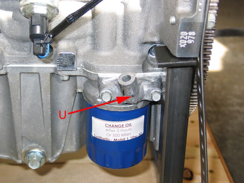 |
U = legacy oil filter bypass housing. Early Gen III motors had the oil-filter bypass mechanism located here. The oil filter bypass allows oil to bypass the oil filter and continue to circulate in the event that the oil filter becomes sufficiently plugged to cause a dangerous drop in oil pressure. If the filter becomes completely clogged with debris, the bypass opens and does not allow the filter to restrict oil flow through the engine. LS2 and other later Gen IV motors switched to an internal filter bypass, located in the oil filter, in 2007. Moving the bypass to the filter ensures that the mechanism is fresh and unobstructed each time the filter is changed. |
|
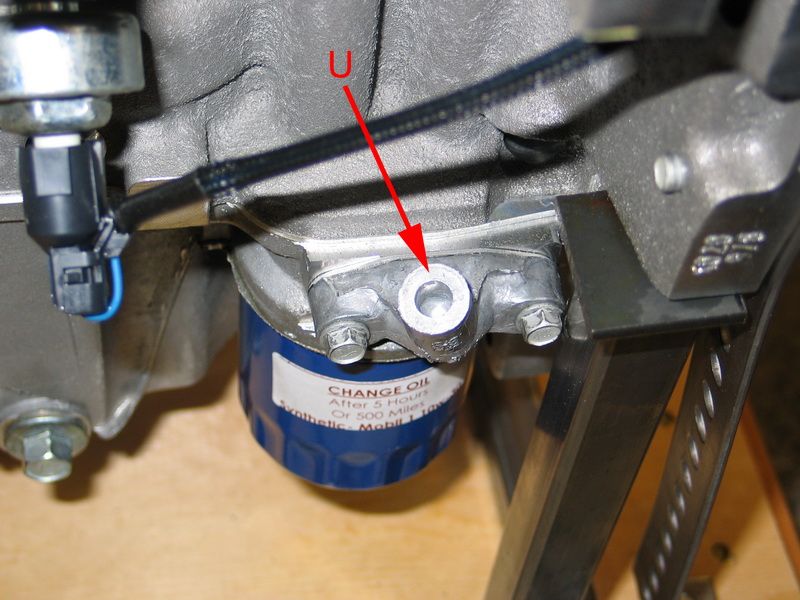 |
The bypass housing remains though, which is a good thing, as it can easily be drilled and tapped to 1/8" NPT and makes a good location for an oil temperature sensor. | |
As good as they are, though, typical parts store "spin-on" filters may not be the best choice. Before we look at the alternatives, let's take a quick look at what the filter does and how. The filter's job is simple - it must filter out contaminants in the oil as the oil flows through. Contaminants include external contaminants - airborne particles such as bacteria and dust that are ingested by the engine; as well as internal contaminants - trace amounts of wear metals from bearings and other internal parts. The trick in making a good filter is balancing efficiency vs flow. Efficiency is the filter’s ability to capture contaminants. The more efficient a filter is, the higher the percentage of contaminants it will remove from the oil. To make a filter more efficient, the spaces between the fibres in the media are made smaller. It would be fairly simple to make a filter 99.99% efficient - the problem is, by doing so, you restrict the flow through the filter. Obviously restricting the flow of the oil is not a good thing, and so the filter's construction must balance efficiency with flow. This is where aftermarket high-quality oil filters can outperform the more common spin-on style. Oil filter design is a delicate balance between efficiency, flow, and lifespan that hinges on the the filter medium, surface area of filter medium and oil pressure. The finer the medium, the smaller the particles it will filter, the greater the percentage of particles it will filter - but the greater the flow restriction across the filter and the more quickly the filter will clog. Designed for the mass market and cheaply produced, most spin-on filters use a paper-based media and reach a compromise between efficiency and flow based on normal automotive use and relying on the pressure bypass valve for backup. Racing filters take a different approach - they use more expensive media (often synthetic), higher quality construction, and do not incorporate a bypass valve. A typical parts store paper-media spin-on oil filter may filter about 60% of particles in the 20-30 micron range (a human hair is about 60 microns in diameter), whereas a cartridge-style racing filter may achieve efficiencies upwards of 80% at the 8-10 micron range. |
||
 |
The blue cylinder to the right side of this pic shows my remote-mounted Canton Racing Products CM -45 canister (cartridge) style filter. The housing is machined aluminum and is plumbed using -12AN fittings. "IN" is at the bottom and "OUT" is on the left side in this pic. This unit is part number 25-106-CM-45. |
|
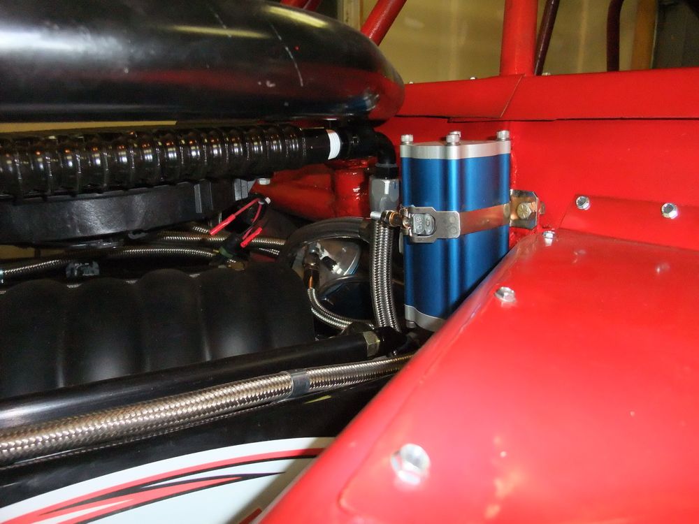 |
This canister oil filter has a 6" tall remote housing, and uses a 4-5/8" synthetic fibre element. The housing is made from a light weight 3-1/4" aluminum square extrusion, 1-1/16" -12 straight O-ring ports, and a removable top cap that allows for easy element replacement. The filter has a blue anodized body and a clear anodized end cap. A stainless steel mounting clamp is included. | |
 |
Another advantage of the an aftermarket racing filter is the "cartridge" design. Unlike a spin-on filter where the filter housing and filter element are contained in a single disposable unit, a cartridge style filter employs a permanent filter housing, with a replaceable inner filter element or cartridge. This design can be a significant advantage in high load, high rpm, high pressure applications as the oil filter housing is much more solidly attached. With a spin-on filter, the only thing keeping all the oil in the engine is the gasket at the base of the filter. If it should loose tension - from heat, vibration, or pressure, the single threaded mounting boss will quickly vibrate loose, the filter housing will depart the vehicle followed shortly thereafter by all the oil. Which isn't good. In contrast, a cartridge style filter uses a filter housing that can be more securely mounted rather than relying only on the base gasket tension. |
|
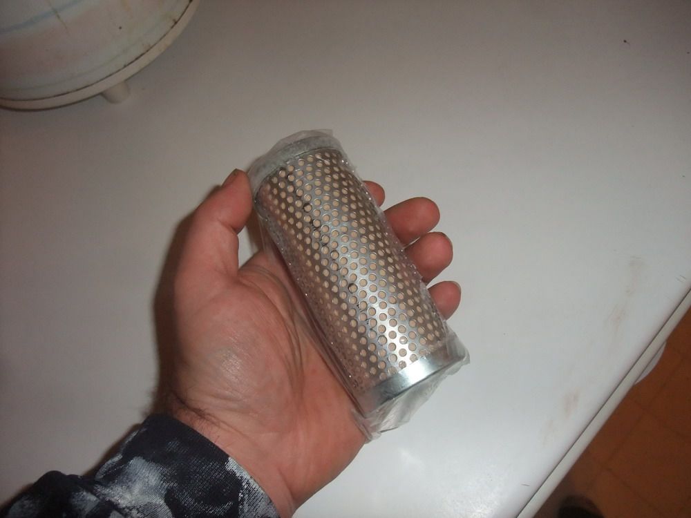 |
This is a picture of the synthetic fibre filter element. CM filters were developed to better protect expensive racing engines. They are designed to handle a continuous high flow of oil while filtering out small particles and without the flow becoming restricted even when the filter is partially contaminated. The synthetic element is not affected by moisture which erodes paper elements, and it withstands pressure surges without collapsing or rupturing. In the years since their development these elements have proven themselves in NASCAR, SCCA, IMCA, IRL, and NHRA racing. |
|
CM elements filter out particles down to 8 microns, half the size of what the average spin-on filter can do, and have a flow rate that is far greater than that required by any automotive application, even when contaminated. Depth filtration extends filter element life because it can catch more contaminates without restricting flow. CM Elements can not be cleaned because they work on depth filtration design where particles are caught within millions of tiny passages which run throughout the element. This design allows for a much greater flow and the ability to hold far more particles than a conventional surface filter. Placement of the filter in the oil circuit is a critical design element, one in which there are two different schools of thought. One method is to place the filter just before the oil re-enters the engine. That is, as late as possible in the circuit. The thinking is, should an external component of the oiling system (like the cooler, plumbing, etc.) either allow entry of foreign material or suffer some internal breakdown (e.g. rust flaking off the inside of a cooler passge); then these contaminents will be filtered before they enter the engine. The other methos is the opposite approach - place the filter as soon as possible after the pump. The thinking here is that the external components themselves deserve protection and that one of the greatest source of contaminents in oil is the engine itself from wear between metal parts. By placing the filter as early as possible in the circuit, these internally generated contaminents can be filtered before they can damage any of the external components of the oiling system. This is particularly useful in the case of an oil accumulator where the internal surfaces are precisely machined and require clean oil for sealing. As another example, should the pump fail or experience wear, if the filter is fitted early in the curcuit, it will protect the downstream components such as accumualtor, cooler, thermostat, and plumbing. One thing to note, if a filter is placed early in the curcuit it will experience, and therefore must be able to withstand, full system pressure; wheras a filter placed after the external circuit and just prior to the engine will experience less pressure as pressure will drop across the circuit. One important consideration in the selection of filter location in the circuit, is the age and condition of the other extrenal components. For example, if the cooler, thermostat, and accumulator are brand new and known to be clean and free of contaminents, as well as of high quality construction and therefore unlikely to break down and introduce contaminents, then placing the filter first in the circuit is a viable option. If, on the other hand, the cooler is a used unit of unknwon history, even if well cleaned prior to installation, it is difficult to be sure of the exact condition, and it therefore could be harbouring contaminents that might enter the oiling circuit. If this were the case and the filter was first in the circuit, such contaminets would reach and pass through the engine before being filtered. In this case, it would be far better to place the filter at the end of the external circuit just prior to the oil entering the engine oil galleys. CoolerUnder hard use, engine oil temperatures can easily exceed 300°F. To help ensure the longest possible oil and engine life, an oil cooler can be a very wise investment. |
||
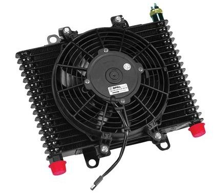 |
I chose a B&M Hi-Tek Cooler with integrated electric fan, Part # 70297. It's a plate & fin oil-to-air cooler with 1/2" NPTF female inlet & outlet fittings. It comes with a 9.5" diameter 12V DC SPAL suction fan. The cooler measures 13.5 in. x 9 in. x 3.5 in. The fan is controlled by a bi-metal
temperature switch. |
|
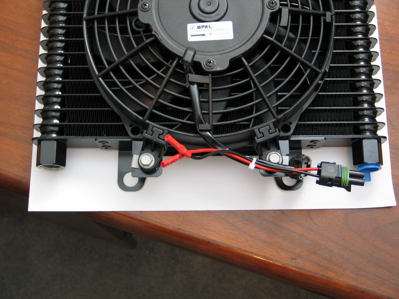 |
I chose this particular unit for 3 reasons: 1) The plate & fin construction is quite rugged and will hold up much better in an off-road environment than other styles (like the copper tube and fin style). 2) It has large 1/2" ports, which is important in an engine oil cooler. Anything smaller would cause an unacceptable pressure drop across the cooler. (for more tech on flow, pressure, and plumbing, see: The Plumbing Bible). 3) It uses a built-in fan, which gives me some flexibility in mounting location without having to mount it in front of the radiator and reduce or block flow through the radiator. In addition, it's a SPAL fan which i know to be high quality, reliable units. |
|
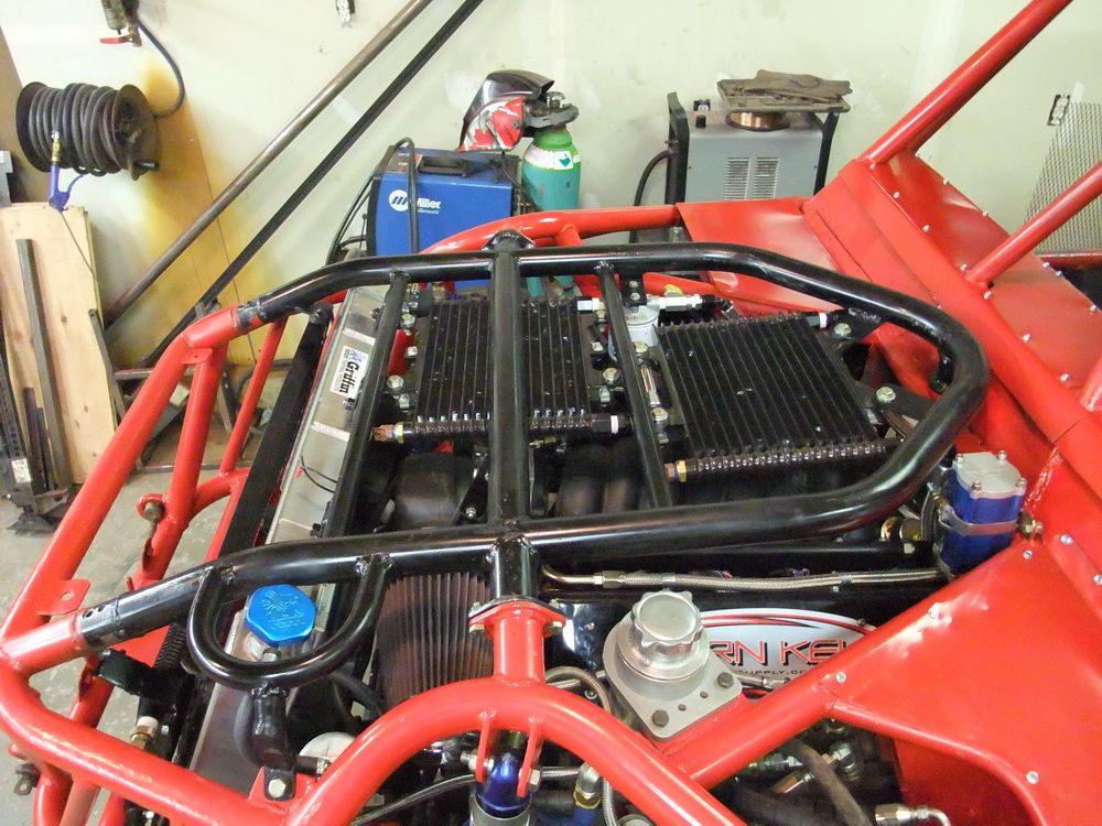 |
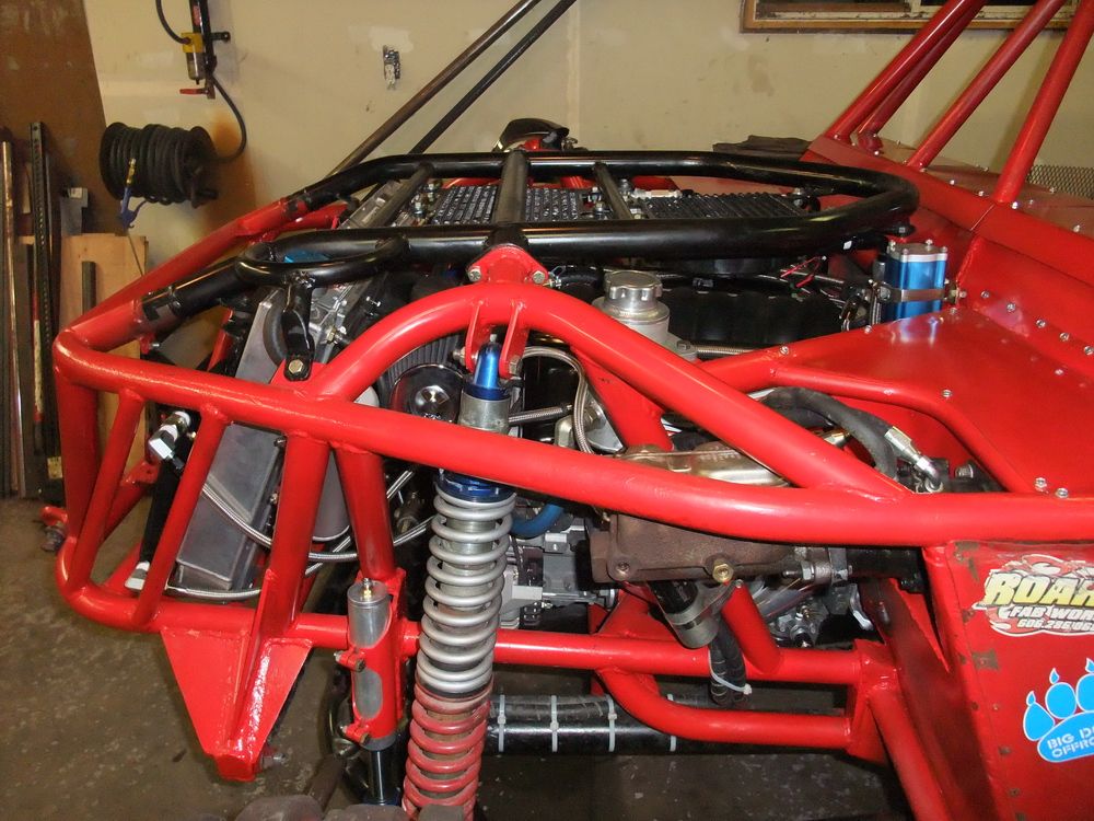
In fact, I chose to install two of these units, one for an oil cooler, and one for a transmission cooler. Like everything else, cooler selection and placement is a matter of compromise - in this case between cooling capacity/efficiency, room for packaging, airflow, and the amount of plumbing you are comfortable running. As mentioned - my top priority was to not place the coolers in front of the rad - I wanted to ensure maximum cool airflow through my rad so the only thing in front is a small PS cooler. These two big oil coolers would have blocked the whole rad and I wasn't happy with that. |
|
That left quite a challenge trying to find space to mount two large coolers where they wouldn't be too vulnerable and where they wouldn't be subjected to excessive heat from the exhaust. Originally I had planned to mount them at the back of the rig, in the same way that some folks mount radiators in the rear. In the end, I got nervous about running the many extra feet of plumbing required and routing the engine's life-blood out of the engine all the way to the rear and back forward again; so I ended up mounting the coolers above the engine as shown. So far they have worked well positioned here, but I'm not convinced this is the aerodynamically optimal placement. The problem is, I'm out of options as the two of them take up a lot of space. |
||
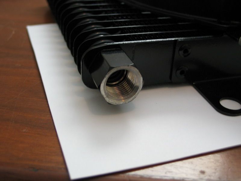 |
The ports are female 1/2" NPTF. NPTF are not the same as regular NPT threads, they are Dryseal USA (American) Standard Taper Pipe Threads aka American National Standard Taper Pipe Thread - Fuel. | |
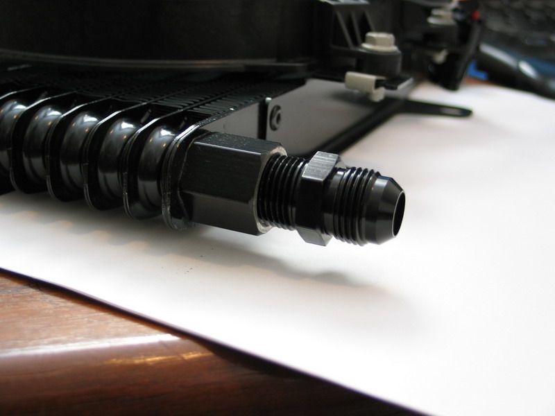 |
You can create a successful seal by screwing an NPT male thread into an NPTF female, as shown here (although you must use a supplementary sealant such as Teflon tape, just as you would in an all-NPT joint). | |
This is the diagram for wiring the fan on the cooler using the integrated thermal switch.
This is what I did at first, but I found the performance of the thermal switch to be poor. That is, it did not reliably switch the fan on and off. The fact that I have the cooler mounted flat horizontally may have been partially responsible for this, but in general these cheap, mass-produced, bi-metallic switches are not real thermostats and not the best way to switch a fan. Also, the on-off settings of the supplied switch are not optimized for engine oil - they are a little on the cool side. |
||
 |
For the time being, I simply bypassed the thermal switches so that the fans come on with the ignition. This is simple and reliable. Of course, the disadvantage to this is that it increases the time it takes the oil to come up to operating temperature, and given what we now know about temperature, viscosity, and lubrication - we know too-cold oil is as bad as too-hot. The proper solution would be to install a true oil thermostat like the one shown below. |
|
| Unfortunately, I hadn't originally planned for one and by the time I realized I needed one I was out of money, out of time, and out of patience with the project. It's the one thing in my entire LS2 install project that I wish I had done differently. | ||
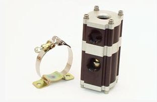 |
This is an example of a proper oil thermostat - this one is part # 22-480 from Canton Racing Products. A proper thermostat like this operates on the same principle as the radiator thermostat and helps your engine’s oil come up to temperature quickly and holds it at the right temperature. Remember, cold oil does not flow and does not lubricate correctly. Plus, pumping cold, viscous oil robs power. |
|
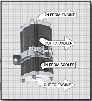 |
This particular thermostat is designed to bypass the oil cooler until the oil reaches 215°F. At 215°F water condensation in the oil will evaporate and the oil will be warm enough to flow and lubricate properly. The thermostat housing is machined from a 3-1/4" square 6061 T6 aluminum extrusion, measures 6" tall and come with a black and clear anodized finish and stainless steel mounting clamp. The oil ports accept 1-1/16" -12 O-ring fittings. (4 fittings required per unit). |
|
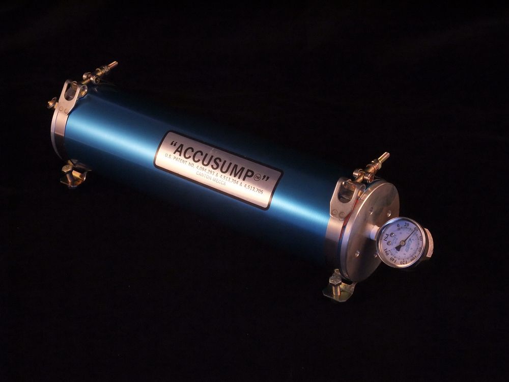
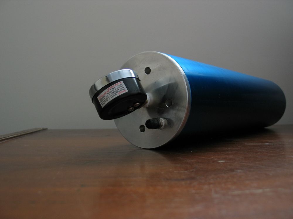
AccumulatorThe heart of my oiling system is the Accusump 3-quart oil accumulator. The purpose of the accumulator is to store a volume or "charge" of pressurized oil when the engine is operating normally so that it can release this pressurized oil to lubricate the engine if normal oil pressure should drop for any reason. This makes it a perfect addition to any offroad rig and invaluable insurance against engine damage that can be caused by flops, rolls, steep climbs, or off-camber driving. How long the engine is protected from oil pressure loss depends on the size of the accumulator used, engine size, and RPM. I chose the biggest available, which holds 3 quarts of pressurized oil. Anecdotally, this will provide from 15 to 60 seconds of running time with total loss of oil pressure (e.g. upside-down with the oil pickup completely uncovered). This should provide plenty of time to get the situation under control and/or shut down the engine before engine damage occurs. However, an accumulator is not designed for, nor will it allow you to drive for extended periods of time with no oil pressure - like when the rubber is sky-side up. Nothing can help you with that except perhaps an aerobatic-aircraft-style dry-sump system. Even the more common automotive-style dry-sump systems (like those on LS7-equipped Corvettes) won't do it, as they are designed for oil control under hard braking and high lateral G loads from cornering. If you look into the complexity of fitting a real aircraft-style dry-sump system that will truly allow you to run the engine indefinitely at any angle (including highly specialized internal engine modifications, multiple scavenge pumps, gimballed tanks, etc.); and realize the cost of such a system quickly outstrips the cost of the engine in the first place; you may well decide, as I did, that a decent accumulator and learning to keep the rubber side down might just be your best option. Due to the way in which it functions, an accumulator can also act as a pre-oiler. That is, it can be installed and plumbed so that just before the engine is shut off a valve is closed, trapping the pressurized oil in the tank. Then, just before the engine is started, the valve can be opened, releasing the pressurized oil to lubricate the engine before the engine is started. I will have some more thoughts on this when we discuss the options for plumbing and valving the accumulator. First let's have a look at the unit and exactly how it works. |
||
|
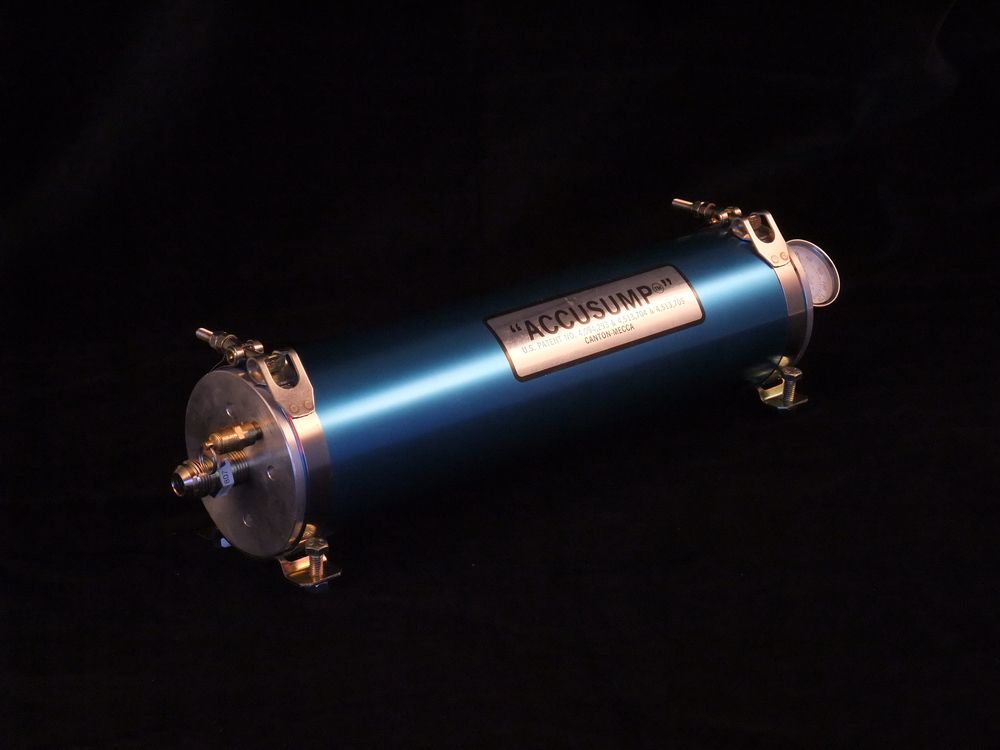
This is the 3-quart Accusump oil accumulator from Canton Racing products. It is essentially a machined aluminum cylinder with an internal floating piston that separates it into two parts - a gas chamber at one end and an oil chamber at the other. The internal floating piston seals against the inside of the tube creating two entirely separate chambers that are sealed from one another and the contents of which never mix. In fact, it is very like the remote reservoir of a coil-over shock. |
|
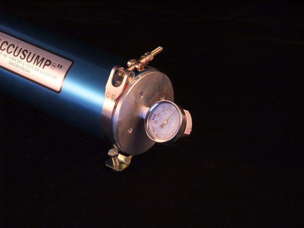 |
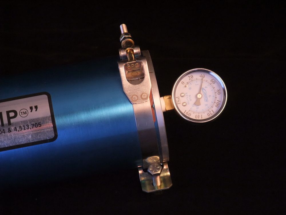
The gas end is the end with the pressure gauge... | |
 |
... this end also has a Schrader valve through which the gas charge is added. The user charges this end with about 10-15 psi of nitrogen (you can use air, but nitrogen is best if you have it available as it contains less moisture, is more pure and stable and is therefore affected less by temperature changes.) When you do this, the pressure you have added will force the internal piston all the way to the other end. |
|
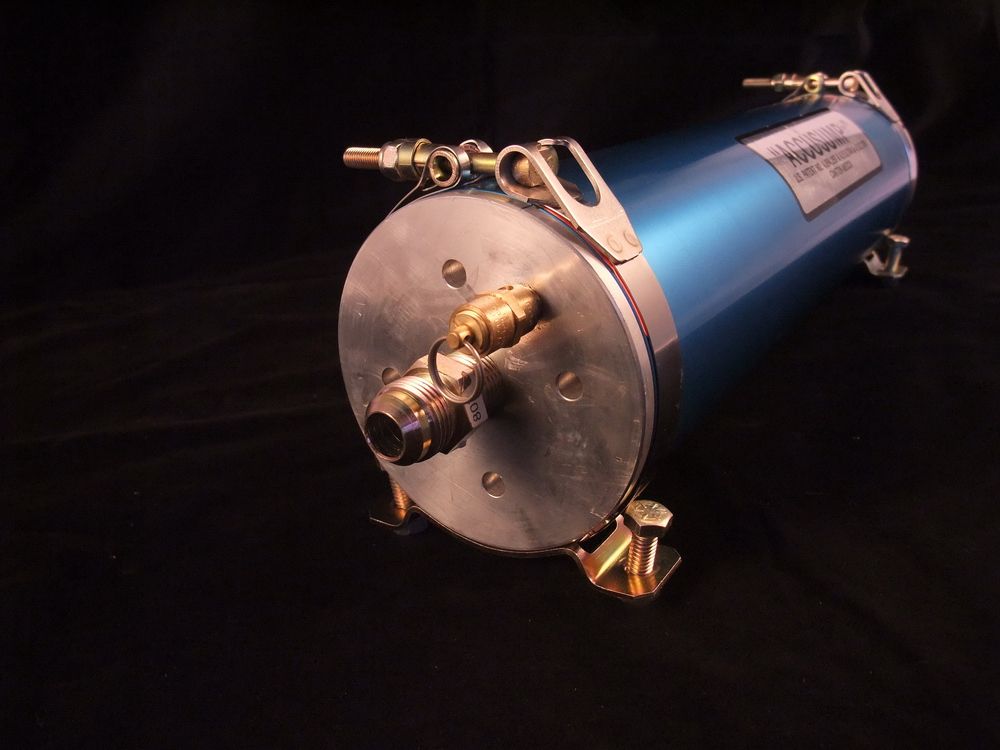 |
At the other end there is an inlet port which is connected to a pressurized oil supply line, and a safety valve that opens in the case of over-pressurization. | |
 |
When the unit is installed and connected to the engine's oil supply circuit, nothing happens, the piston stays at the oil end until... | |
 |
... the user starts the engine. at this point the engine develops oil pressure that exceeds the pressure of the gas charge in the gas chamber. When this happens, the oil pressure pushes back against the piston and forces it back near the gas end. In this way, the majority of the accumulator is filled with pressurized oil when the engine is running normally. The engine's oil pressure will now register on the gauge. Now, when there is a drop in oil pressure below the value of the pressure in the gas side (say 10 psi), the gas pressure takes over and forces the oil back out of the accumulator and into the engine for lubrication. |
|
When normal oil pressure is restored by the oil pump, the pressurized oil again overcomes the gas pressure and the accumulator is once again charged with oil and ready to work again. The following animated graphic illustrates the charging of the oil accumulator when the oil pump is functioning normally. As you can see, the oil pump draws oil from the tank (oil pan), and sends it to the engine for lubrication. Along the way, some of this pressurized oil is diverted and fills the accumulator, pushing the IFP towards the gas side (the end with the pressure gauge).
When the oil pickup tube in the oil pan is uncovered, as here, the oil pump loses suction and no longer pumps, and therefore system oil pressure drops. When this happens, the pressure in the gas side of the accumulator takes over and forces the piston down which pushes the oil out and into the engine for lubrication. If the supply line to the accumulator uses a "T" from the normal oil circuit, as shown in this example, a check-valve is used to ensure the precious supply of oil is not wasted by being sent backward through the circuit into the oil tank (oil pan).
|
||
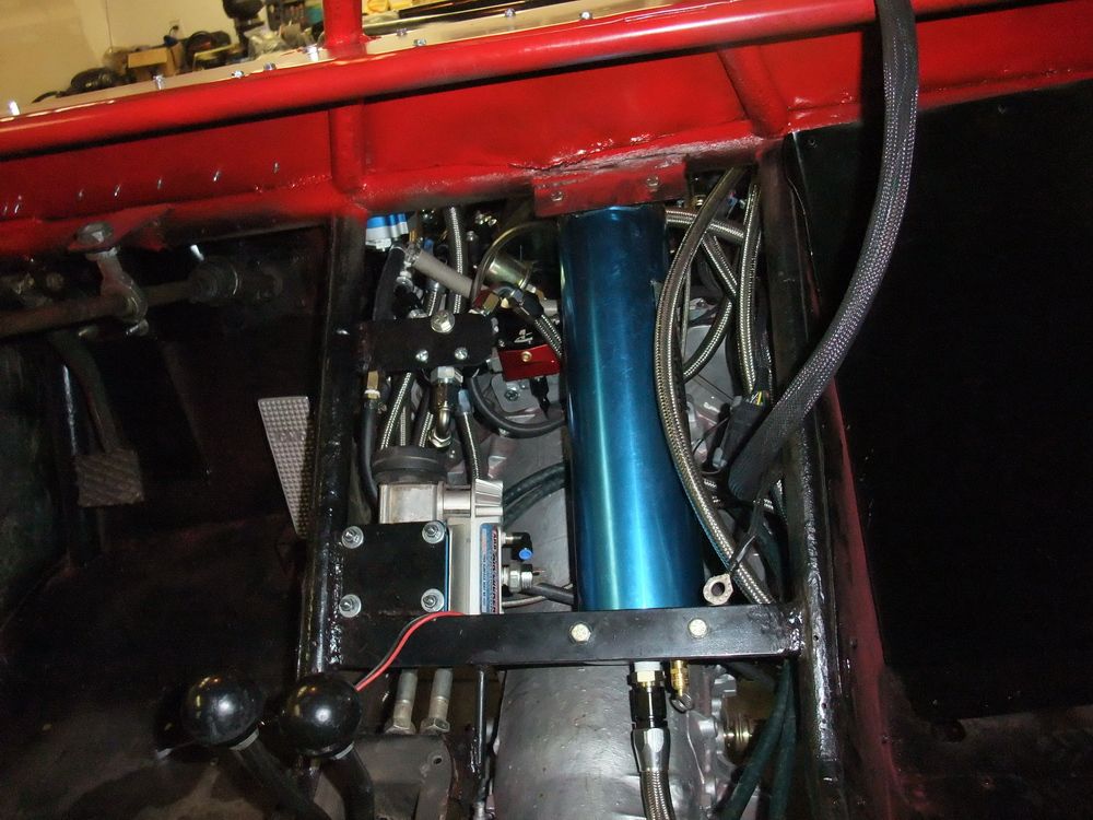 |
The length of time the accumulator buys you depends on its size and therefore the amount of oil it can store. I chose the largest available, which is the 3-quart model, but fitting such a beast can be a real challenge. Mine is mounted in the "transmission tunnel" just below the interior panels. You don't want to mount an accumulator in the passenger compartment as you want to avoid running hot pressurized oil in the vicinity of personnel. |
|
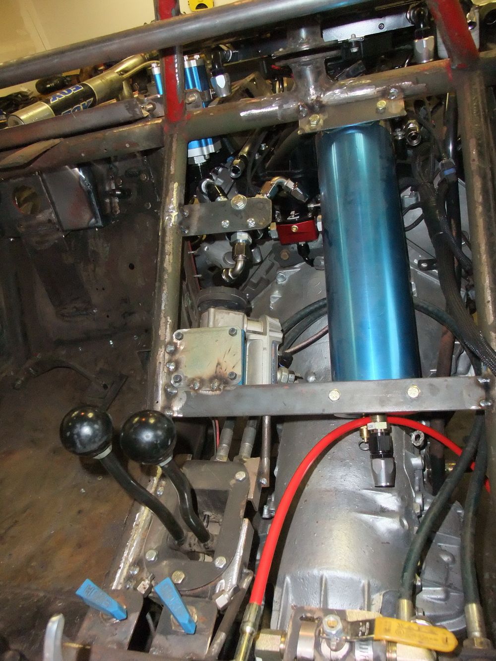 |
You can mount the unit in any orientation and it will work, but there are a couple of considerations to keep in mind as you struggle to find the room to fit the beast. 1) It is best if you can mount it with the oil-end at least slightly higher than the gas-end, as this will ensure any bubbles in the oil (engine oil can cavitate and aerate under hard use) do not get trapped. Note that this is NOT how mine is mounted in this picture as I needed to mount it as shown so the plumbing routing would work and I would still be able to access the pressure gauge and schrader valve. 2) The cylinder must ONLY be clamped at the very ends, otherwise tightening the clamps may slightly distort the tube and thereby cause the floating piston to hang up. 3) Mount the accumulator where it will not be stressed, twisted, bent, subjected to exhaust heat, misused as a support or step, or where it will be vulnerable to rock or debris damage. 4) For safety, avoid plumbing hot pressurized oil through the passenger compartment. 5) Install the accumulator with due consideration to the required plumbing and the placement of any valves, if used. See below for plumbing and valve considerations. |
|
|
This picture shows the gas-end of my accumulator in its installed position. It is important that access to the schrader valve be maintained in the installed position so that necessary adjustments or top-up to the gas charge can be made. In this picture, the supplied pressure gauge is still installed. However, after installation I found myself wanting to monitor the gauge and the accumulator's performance. So, I installed a slight modification. The port for the gauge is 1/4" NPT, so I removed the gauge, installed a 1/4" NPT to 1/8" NPT adapter, and then installed an old mechanical-style oil pressure gauge I had lying around. |
|
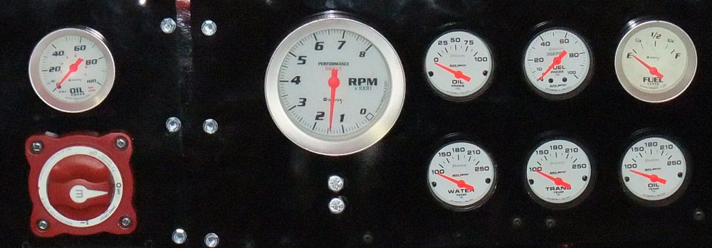 |
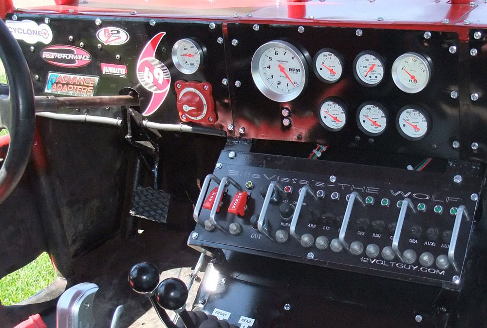
In this pic, the accumulator gauge is immediately above the large red power switch, and the normal oil pressure gauge is on the top row just to the right of the tachometer. When the accumulator is charged, the accumulator gauge will show this pressure (note, accumulator not charged when this pic taken). This pressure will of course vary somewhat with ambient temperature, so adjustments at the schrader valve may need to be made (one reason why you need to be able to access it). The instructions say to charge to 7-10 psi. This is the pressure below which oil pressure must fall for the accusump to kick in and discharge oil to the engine. It is also then, the pressure above which oil pressure must build in order for the accusump to fill or "recharge". On my gauge 7-10 psi is almost unreadable and so I run my accumulator at 10-15 psi gas charge pressure. |
|
Accumulator Plumbing.Obviously, the accumulator must be installed in the pressure side of the engine's oiling system. That is, between the pump and the engine oil galleys. There are two main methods to plumb the accumulator, they are:
|
||
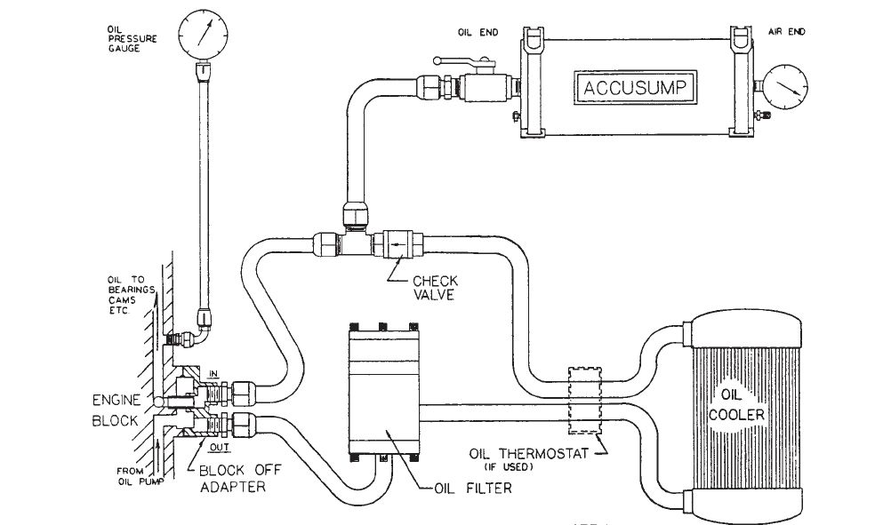 |
Inline T-connection.The advantage to this method, pictured at left, is that it can be done on any engine. Even if you don't have any external oil system components, you can use a "sandwich" style oil filter adapter to provide a port into which you can plumb the accumulator. |
|
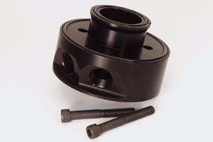 |
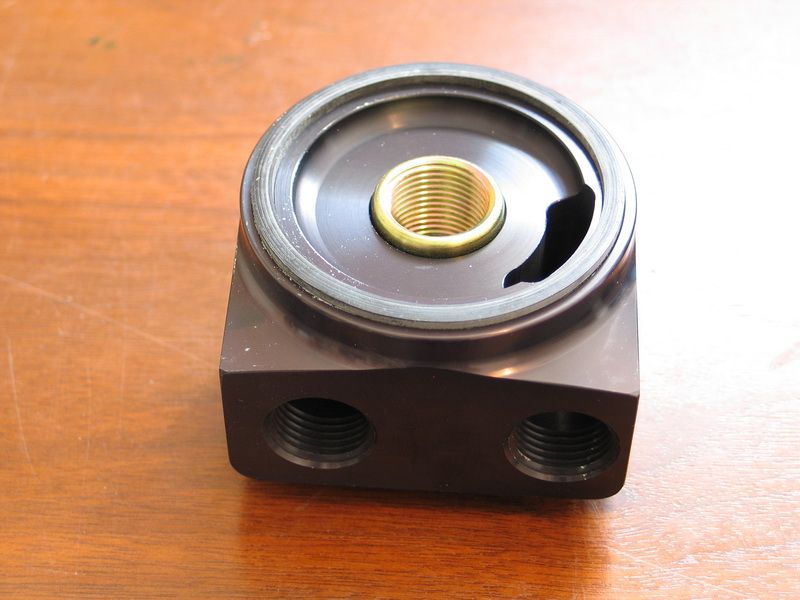
This is a "sandwich" adapter. It gets its name because it gets sandwiched between the engine block and spin-on style oil filter. It gets installed in the stock location of the oil filter, and then the oil filter is attached to the other side. In this manner, it provide one or more oil ports - one of which can be used to plumb the accumulator. | |
| Alternatively, if you have other external oiling components, including a remote oil filter, your system will already incorporate some kind of input adapter, often called an "oil cooler adapter" or a "remote oil filter adapter". | ||
 |
My system uses this 90° rotating remote oil filter adapter.Made from billet aluminum, it is Canton part number: 22-593 (53020807). It spins-on to the stock 13/16"-16TPI oil filter thread and seals against the pan with stock diameter 2-5/8" seal. It provides 1/2" NPT in and out ports for plumbing a remote filter. From this view, the port on the left is the INLET and the port on the right is the OUTLET. Its design permits it to be rotated, providing for adjustable positioning of the the two 90 degree inlet and outlet ports, which can greatly simplify plumbing. |
|
Do not confuse a sandwich adapter with an input adapter, as the two are different and not interchangeable. Sandwich adapters access oil flow as it passes to or from the filter and provide a port for installing items such as an external oil pump, or an accumulator. A sandwich adapter will flow oil to the engine whether or not the oil ports are used. An input adapter diverts the oil flow and provides an in and out port for installing an oil cooler or remote filter. The design of the input adapter requires the oil exiting the adapter to return back to the adapter, you cannot plug off the ports in an input (cooler/remote filter) adapter. That said, I have chosen not to plumb the accumulator inline with my input adapter and the other oiling system components because of the disadvantages of this approach. Namely, that it requires a T-fitting connection, and as such, a check-valve must be used to prevent oil discharged from the accumulator from flowing the wrong way. The problem with this is - in order for the orifice of the check valve to be large enough as to not cause any flow restriction (last thing you want in an external oil system is to restrict the flow of precious engine oil) the body and therefore connections of the check valve have to be way oversized - which means taking up a lot of space and cobbling together all sorts of multi-step adapters (each a potential leak point) to integrate the over-size check valve into the oil lines. I hate doing that. The other problem with the "T" approach is the length and complexity of the plumbing to charge and discharge the accumulator when, what you really need in a system designed to protect your engine as it starves for oil, is a nice, short, simple, large diameter, high-flow, straight shot from the engine oil galley to the accumulator. |
||
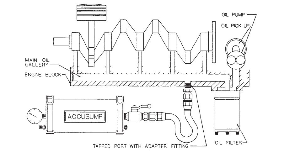 |
Direct to BlockWhich leads to the other method of plumbing an accumulator - connecting it directly to the engine's oil galley. The picture at left of this approach shows an engine with a standard spin-on style oil filter but this can obviously be done with or without a remote filter and/or other external components. It is definitely the preferred method, but the trick is finding an appropriate port in the engine, of the correct size, to which you can connect the accumulator. An accumulator should use -06 size plumbing as a very bare minimum, with -08 being much preferred and -10 even better (though sometimes harder to fit). Of course, the minimum diameter will depend somewhat on the length of the plumbing used too, with the longer the oil line to the accumulator, the larger diameter it should be. |
|
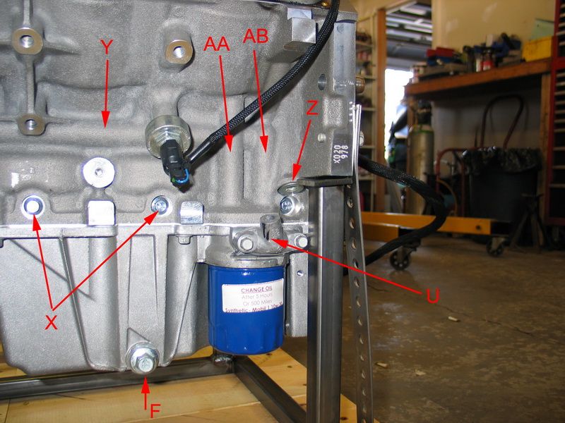 |
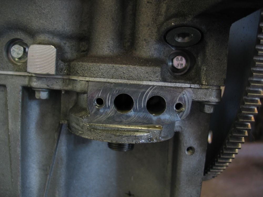
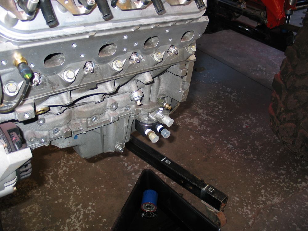
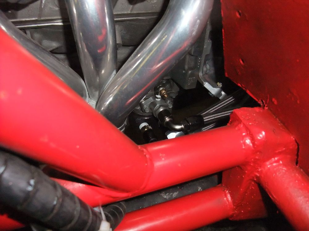
This pic shows some of the features of my LS2 engine block with regards to oiling. Most of these features are common to other Gen III/IV V8's. Y = Main oil galley. AA = Dirty oil galley, from oil pump to filter. AB = Clean oil galley, from filter up to main feed galley (runs through the lifter bodies) and top of engine through pushrod passages. Z = Main oil galley port, 16mm x 1.5 straight thread with crush washer. This location is post-filter and makes an excellent location to plumb an oil accumulator - IF you can get an appropriate fitting installed without having to grind the block. |
|
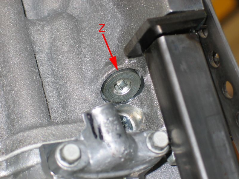 |
Z = Main oil galley port. You can see how tight it is to try and get a fitting installed in this port, especially one that converts to a male AN fitting sufficiently large for oil accumulator plumbing (i.e. AN-10). So, it seems this port would have been an excellent place to plumb an accumulator - I just couldn't find a way to accomplish it. |
|
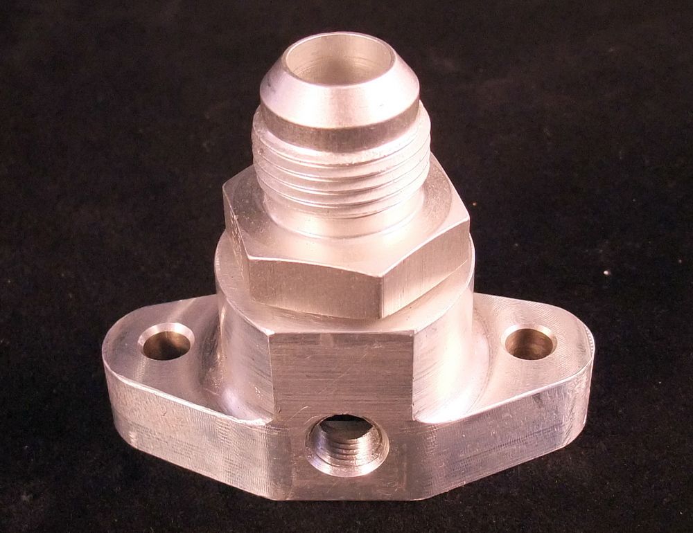 |
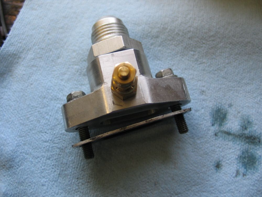
I was pondering what to do, and whether I would have to install my accumulator using a "T" fitting, when my friend Adam Woodlee from Wide Open Design Machine & Fab came through with a brilliant idea and a great little component to save the day. This is the Woodlee oil accumulator adapter for Gen III/IV V8's like my LS2. |
|
|
It is designed to fit in place of the stock oil filter bypass housing (labelled "U" in this pic). | |
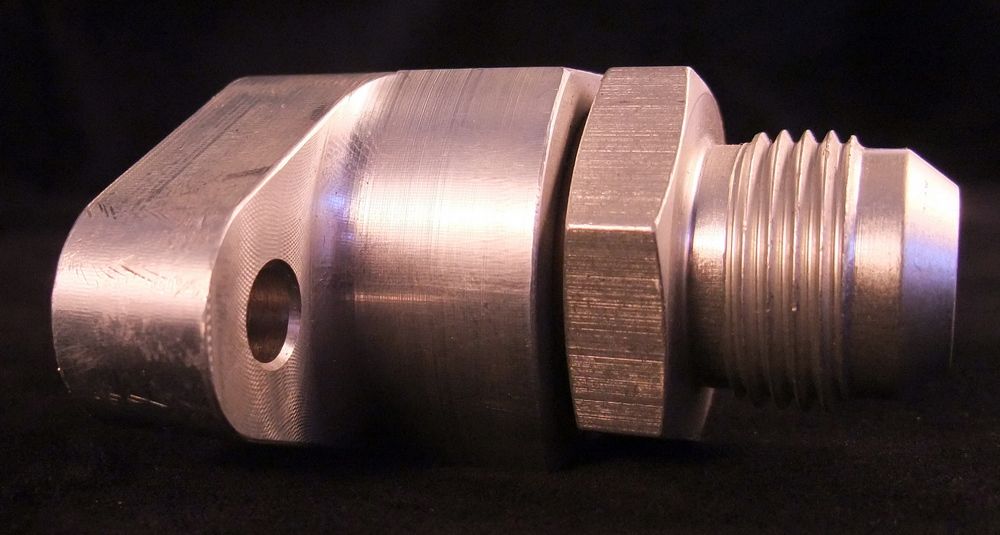 |
Machined from billet aluminum, it incorporates a built-in -10AN male port for plumbing the oil accumulator line... | |
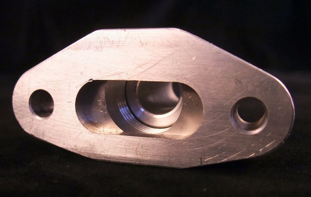 |
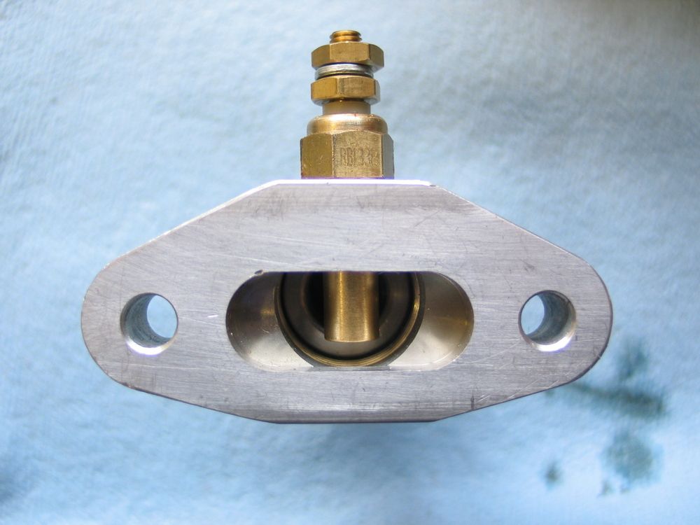
... and is machined on the back side to use the stock gasket and fasteners. | |
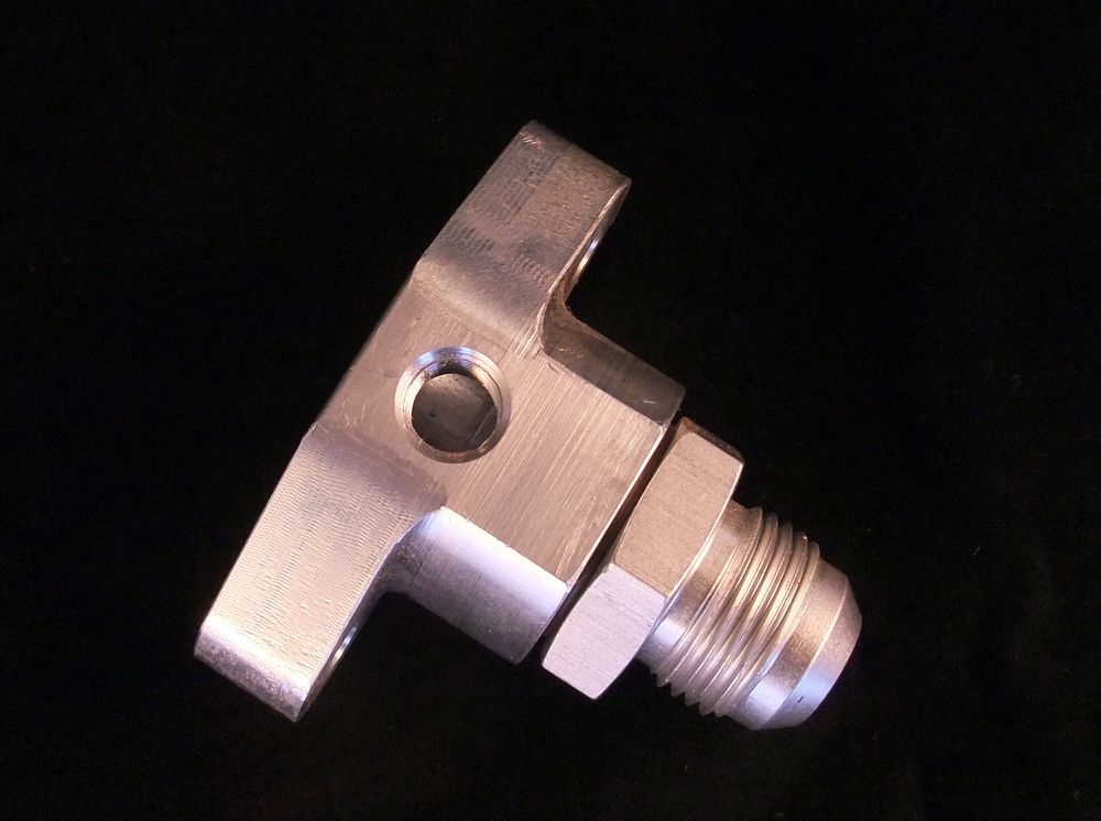 |
It also has a 1/8" NPT port machined in the top surface to facilitate an oil pressure gauge or oil temperature gauge. | |
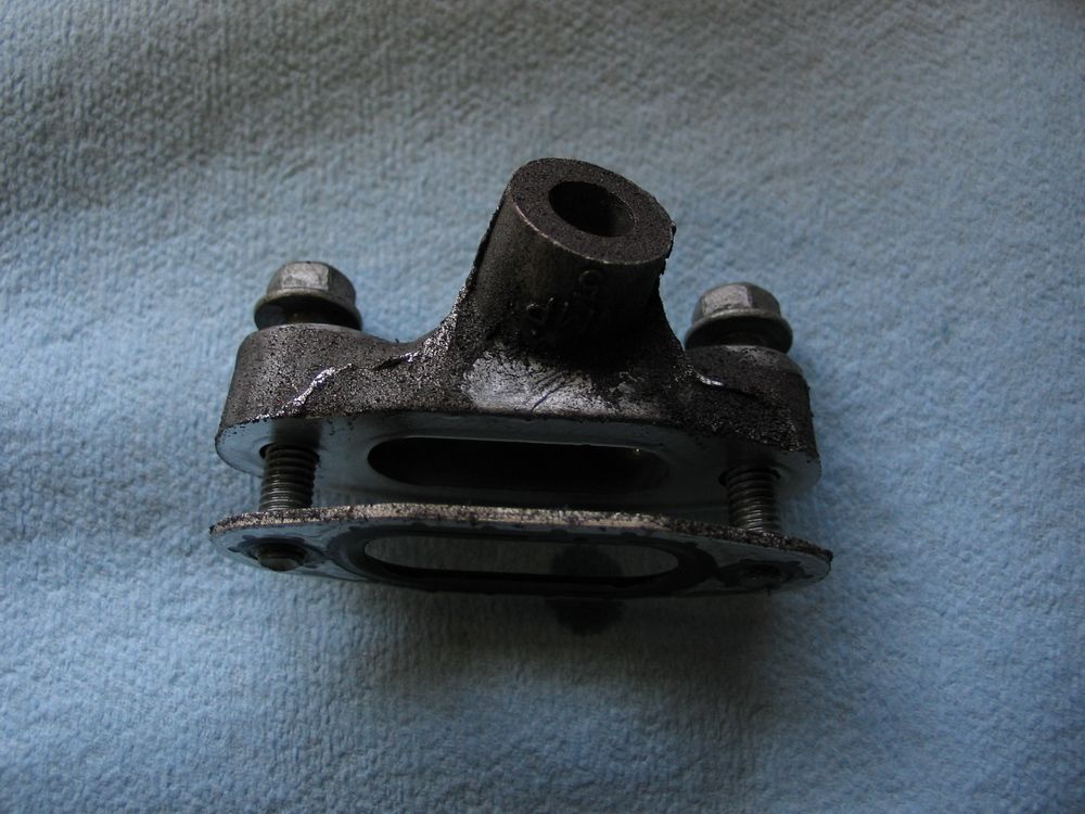 |
This is the stock oil filter bypass housing removed from the block. The Gasket and two bolts are re-used. | |
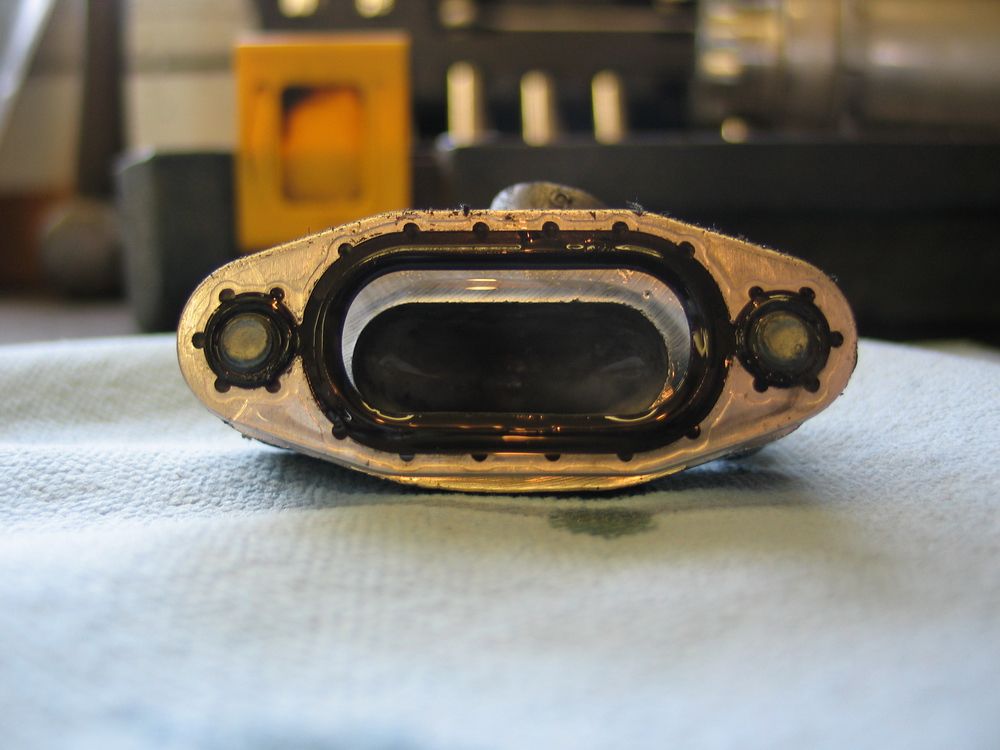 |
The stock steel-and-rubber oil filter bypass housing gasket. | |
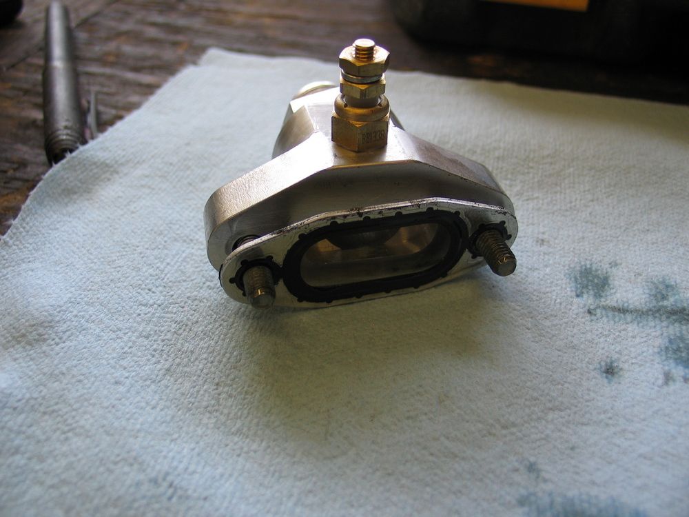 |
Here is the Woodlee adapter with an oil temperature sending unit installed and the stock bolts and gasket in place for installation to the block. | |
 |
It is an ingenious idea and a great little component that makes for the perfect way to plumb an oil accumulator to an LS engine. If you have an LS engine you should definitely have an accumulator to protect it, and if you have an accumulator and an LS engine, you should definitely plumb them using this clever little custom adapter. |
|
 |
One catch, if you plan on using the 1/8" NPT port, depending on what you screw into it (shown is an electric gauge temp sending unit), it may block a large portion of the flow. I found the example at left to block too much of the flow for me to be comfortable with, so I installed the temp sender in a T-fitting attached to the top of the Woodlee adapter (see picture two rows below). |
|
 |
This is the block with the stock oil filter bypass housing removed... | |
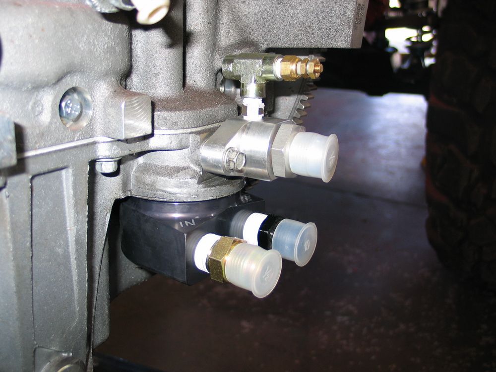 |
...and this shows both my Canton remote oil filter adapter and the Woodlee accumulator adapter installed. You can clearly see the:
|
|
 |
Another view of the oil system adapters in place on the block. The nice thing about the male -10AN fittings... |
|
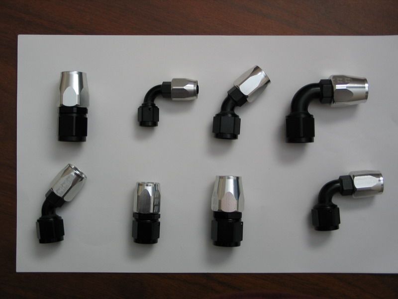 |
... is that you can connect to them using 45°, 90°, 180°, or straight hose ends, like these from Russell Performance. | |
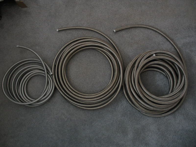 |
For the entire plumbing system in my buggy, including the oiling system, I exclusively used Russell Performance ProFlex hose in -10, -08, and -06 sizes... | |
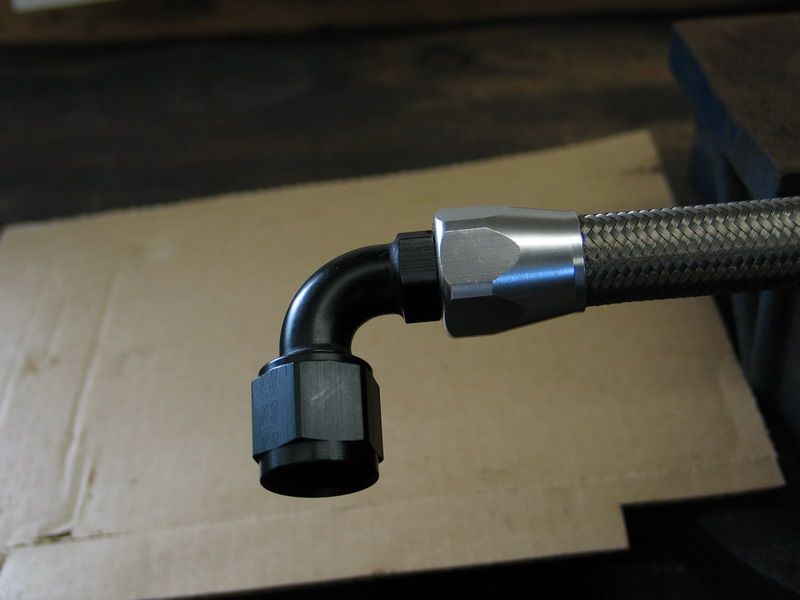 |
...combined with full-flow field-attachable AN hose-ends in ProClassic black/clear aluminum finish. I used -10AN to plumb the entire oiling system, including remote filter, cooler, and accumulator. |
|
 |
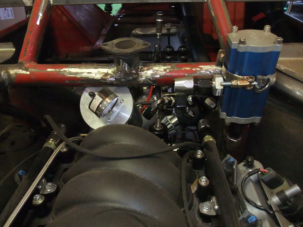
The result is a neat and tidy plumbing job that routes the critical oil lines in an optimum fashion. Here, 90° hose ends are used to route the lines away from the heat of the block-hugger Doug Thorley exhaust header. |
|
Valving the AccumulatorOne final consideration in installing and using an accumulator is whether or not to valve the accumulator, and if so, which kind of valve to use. This decision can have a large effect on where and how you mount the accumulator and the size and routing of the plumbing to it. Let me explain. As per the description of how the accumulator works with the engine running, we can see that it is "fully automatic", requiring no intervention or operation from the driver, and requiring only a direct connection to the pressure side of the engine oiling system (whether by "T" connection or direct connection to the block). Simple and easy. So why the valve? Well, if we install a valve capable of being operated by the driver, the accumulator can function as a pre-oiler as well, meaning it can be used to supply pressurized engine oil to the engine before starting, which aides in limiting wear during startup. It works like this. As we know, while the engine is running, the accumulator is charged with pressurized oil. Before shutting off the engine, if we close a valve located between the accumulator and the engine, we can "trap" a full load of pressurized oil in the accumulator. Then we shut the engine off. Now, before starting the engine, if we open the valve, the trapped or stored pressurized oil is supplied to the engine providing lubrication in the critical first moments before the oil pump is supplying full oil pressure to the engine. Once the engine is started, the valve remains open and the accumulator functions as we have already described. |
||
|
There are three basic ways to install a valve:
|
|
Because I wanted a simple, reliable, bulletproof method of protecting my engine from loss of oil pressure in all conditions I ended up deciding to delete the valve altogether and run a big, fat, straight, simple -10AN stainless steel hose directly from engine oil galley to accumulator. Here's why:
|
||
 |
Plenty of knobs dials and switches - don't need any extras! | |
 |
A not-terribly-relevant picture of the electrical oil pressure sender installed using a 45° adapter in the port at the driver side rear of the LS2 head - but I didn't have any better place to put it in this article! | |
The following information on accumulator checks and procedures are taken largely from the Canton Accusump Instruction Booklet. SETTING THE PRE-CHARGE After your accumulator is installed, perform the following checks / procedure: With the valve (if you have one) in the open position (electric units energized) and the engine not running; pressurize the
Accusump™ to 60 psi. This will ensure all the oil is out of the unit and the piston is all the way to the oil end. While
the Accusump™ is pressurized to 60 psi check all the fittings (gauges and lines) for leaks. Apply soapy water to each
area and check for bubbles. If possible, wait overnight to ensure there is no loss of pressure. For the unit to operate
correctly there cannot be any leaks in the air side. Temperature change will affect pressure. Under normal conditions the pre-charge should not need resetting after the initial set up. However, if a leak occurs Under no circumstances should the safety valve be removed, as this will void the warranty. If oil leaks from the safety valve, be sure that it is sealed with Teflon tape and tightened; the safety valve is hand tight when delivered and requires final tightening after installation of the Accusump™ valve. If oil still leaks from the safety valve, there is a problem in the installation. These valves are very reliable and are set to open at 175 PSI, which is far above the pressure the unit would see if installed correctly. NORMAL OPERATION OF THE ACCUSUMP Pre-oiling With manual valve units: immediately before starting the engine, open the oil valve on the Accusump™. This will Surge Control During operation of the engine, the Accusump™ will operate automatically to supply oil to the engine any time that Shut Down During shut down the Accusump™ will hold whatever pressure your engine has at the time it is shut off. On manual NORMAL CARE There are Accusump™ units that have been in service for many years and have bores which look like new. The key ENGINE FAILURES Should an engine failure occur or the oil become contaminated the Accusump™ should be cleaned and tested.
The following precautions must be taken for your Accusump™ to operate correctly. Failure to do so can result in CAUTION!!!
TESTING YOUR ACCUSUMP™ Check the Accusump's ability to fill. Check the Discharge Check the Refill TROUBLE SHOOTING Accusump™ not filling or filling too slowly Other reasons for slow or no refill: Accusump™ not discharging correctly If you are using the canton EPC electric valve you should note that it operates in a unique way from the other valves. The EPC valve is designed to only discharge at the threshold pressure of the EPC valve, regardless of the Accusump's total held pressure. The EPC unit will only discharge when the engine pressure is at or below the threshold pressure. Accusump™ not holding a pre-charge Accusump™ leaking Final Accumulator ThoughtsLet me close the topic of oil accumulators with a few more thoughts on why I chose to install one, and why I prefer it over a fancy oil pan design. The facts are:
That's why I don't bother with aftermarket pans and why I use an accumulator. People with fancy oil pans that drive like old ladies are free to disagree with me ;-) PCV Oil ControlThe final topic I'm going to tackle on oil and oiling is the subject of oil control. The term "oil control" refers to designs and practices used to eliminate or minimize the unwanted consumption of motor oil as the engine is operated. It encompasses a number of diverse topics including selection of the right viscosity of oil for the engine, allowing the engine oil to warm up properly before hard use / high revs, and keeping the engine (particularly piston rings and valvetrain) in good working order. An important component in oil control is the Positive Crankcase Ventilation or PCV system. The purpose of the PCV system is to relieve the pressurized gasses created in the crankcase by the pumping of the pistons, scavenge these vapours, filter out the oil vapour so it is not consumed by combustion, and then return the vapours to the intake manifold to be combusted. In order to do this, crankcase vapours are drawn from the crankcase, up through the engine where they exit through the valley cover and are carried via an external tube to the intake manifold. This is the so-called "dirty" side of the system as the gasses contain oil vapour. Of course, if we are removing gas from the crankcase, we must also replace it. The "clean" side of the PCV system provides fresh air from the throttle body (i.e. post air filter) to a port in the right rocker cover, to replace the scavenged crankcase vapours. |
||
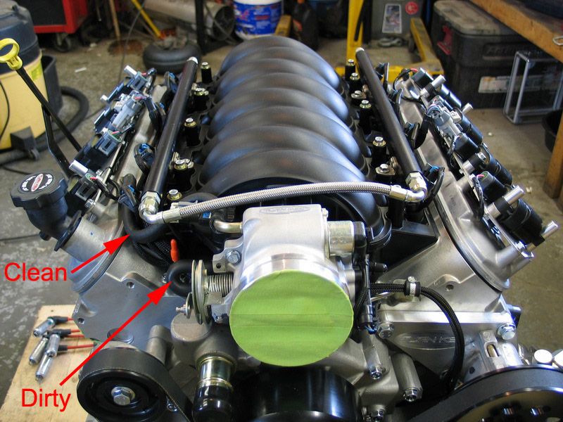 |
Uppermost hose is the clean side. Small, looped hose is the dirty side. |
|
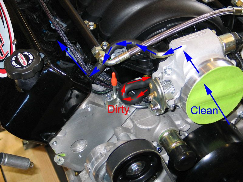 |
LS2 PCV system air-flow illustrated. | |
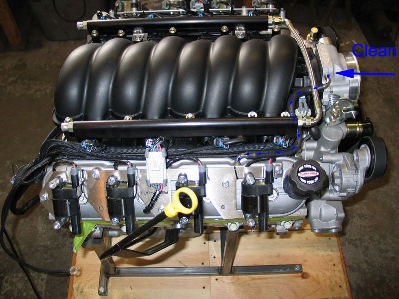 |
This pic illustrates the path that fresh, clean air takes in the system. | |
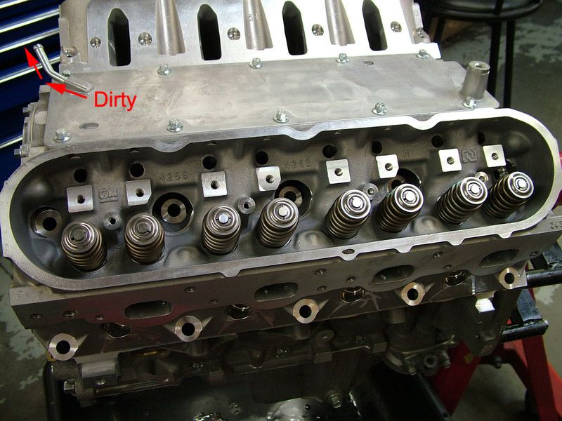 |
This pic illustrates the port in the valley cover from which the dirty crankcase vapours are drawn. | |
What can't be seen in the above pics are the oil separators. Externally, the LS2 PCV system appears only to be a couple of hoses - a clean one connecting the throttle body to the rocker cover, and a dirty one connecting the valley cover to the intake. But there is more to the system than that. There are air/oil separators on both sides of the system. The most important is the dirty-side separator, as that is where the oil is in the crankcase vapours. Essentially, the separator is a baffling system that separate the oil from the air and drops it back into the crankcase so that only the air is burned. The better the oil is separated, the less oil will be burned, and the less oil consumption will occur. There is also a separator on the clean side. This is required because, under certain conditions (like wide open throttle), blow-by increases to the point that it exceeds the capacity of the dirty side to extract and consume the gasses. When this happens, the air flow can reverse, and air comes out of the crankcase from the clean side. Obviously, under these conditions, you don't want to dump a lot of oil into the throttle body, so a separator is also required on the clean side. Under normal conditions, this reverse-flow situation is not a problem, because the intake manifold produces enough vacuum to constantly purge the crankcase vapours adequately. There will always be some oil consumption, but it is normally very little. However, at sustained WOT and high engine speed there is no longer sufficient manifold vacuum to help pull the air from the crankcase. At the same time, more blow-by is produced. This combination may exceed the capacity of the dirty air side, which is sized for most normal light load engine operation, (if it were sized larger, the engine would consume excessive oil under normal conditions, which would not be beneficial) and reverse flow can occur. Therefore, the clean side also has a separator to ensure reverse-flow conditions don't dump oil into the throttle body. All of this said, as good as the stock PCV system may be, in spirited use, it can use a little help, or you can end up with oil in the intake. The help comes in the form of installing a small air/oil separator in the "dirty side". Instead of the standard hose simply looping between the valley cover and the intake manifold, we install a small filter to separate any remaining oil vapour in the blowby gasses, before directing the gas back into the intake manifold to be combusted. |
||
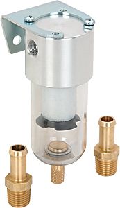 |
There are several makes and brands of oil separators for this purpose to choose from - including some pretty bling machined aluminum units. However, I chose this cheap and simple unit from JEGS, primarily because it is transparent, and therefore the oil level in the bowl can easily be monitored. Specs of the unit include:
|
|
If it looks a lot like a small version of the air filter on your shop compressor, that's because it is. It is essentially exactly the same thing (technically known as a coalescing filter). Update: Reader Steve recently alerted me to these other two possibilities. I have no expeience in using either, but they may be worth checking out. |
||
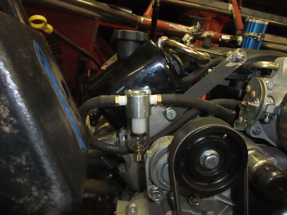 |
Here is the unit installed on the front of the passenger side head. | |
|
||
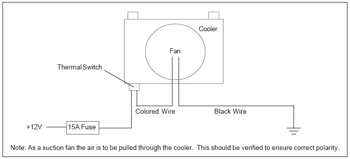
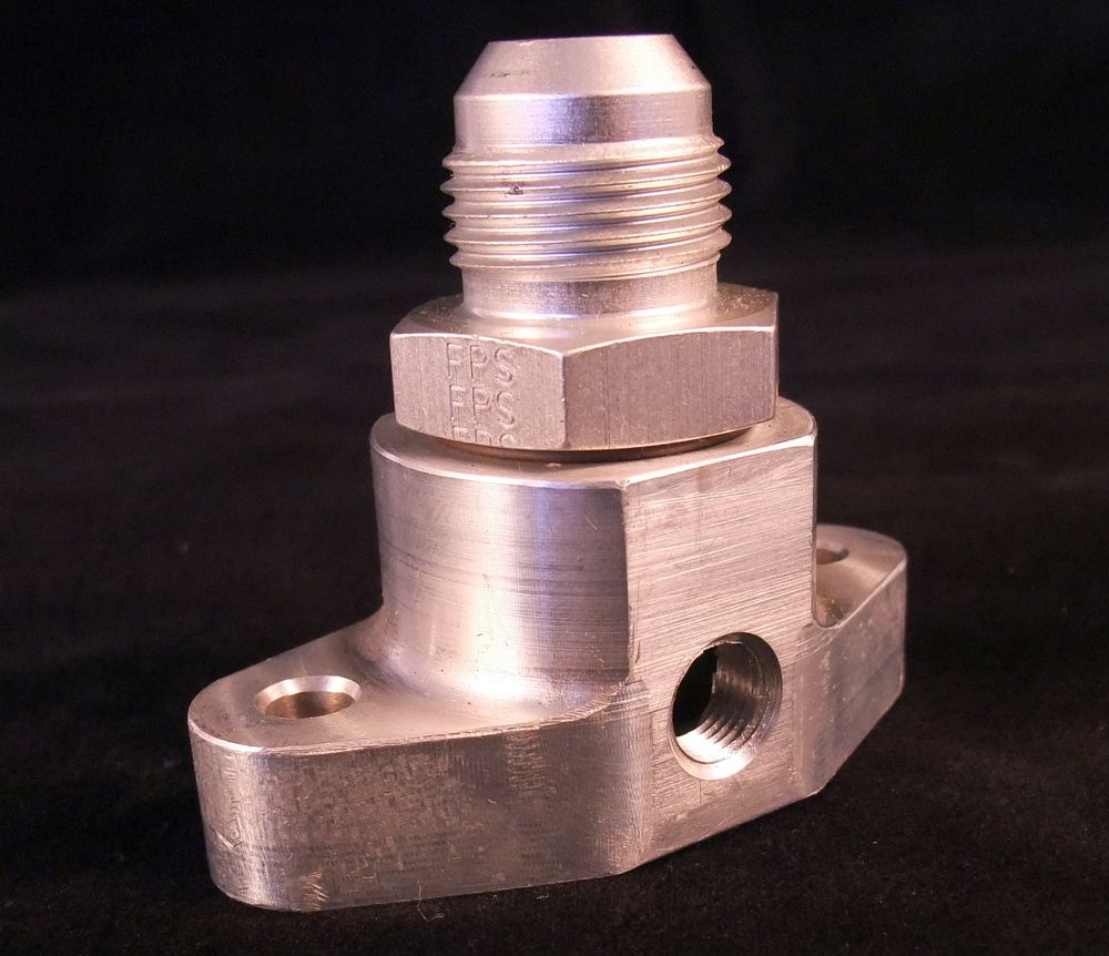 |
Sources: Wide Open Design Machine & Fab435 Cut Off Rd. |
|