 |
Fuel Cell Tech
By Bill "BillaVista" Ansell |
IntroductionNot surprisingly, most OEM's place fuel tanks under the vehicle, usually along the side and/or at the rear. The problem is, for a hardcore offroad rig, this positioning leaves the fuel tank vulnerable to damage and also robs valuable space that is needed for suspension components and to allow axle articulation. Sooner or later the serious offroader is faced with either re-locating the stock tank or switching to a fuel cell. There are several different types of aftermarket fuel cells available that are suitable for an offroad rig. One of the simplest, cheapest, and most effective is the so-called "bladder in a box" style. |
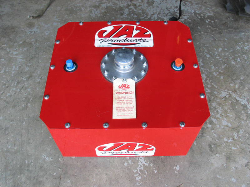 |
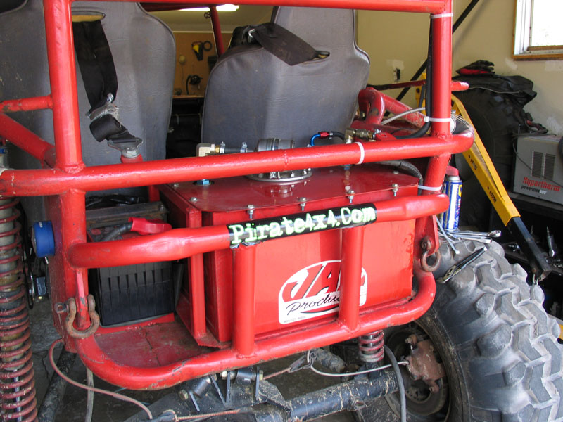
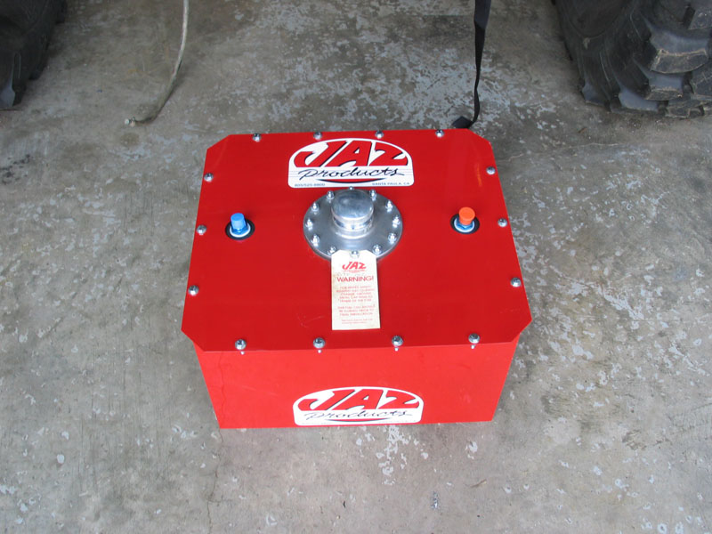
Custom built aluminum cells are great for maximizing available space but need to be constructed by an expert aluminum welder and can be susceptible to fatigue cracking, especially at the mounting points. On the other hand, if you have the room available, installing a simple off-the-shelf "bladder in a box" style fuel cell is *almost* a plug-and-play affair. Follow along as I install a 12 gallon Jaz Pro Sport fuel cell in my rock buggy and, as usual, learn a few things the hard way. |
|
 |
Specs: Model: Jaz Pro Sport with 90° Filler & Cap Features:
|
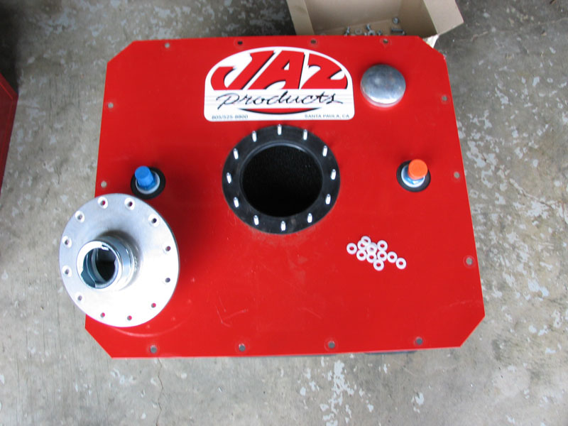 |
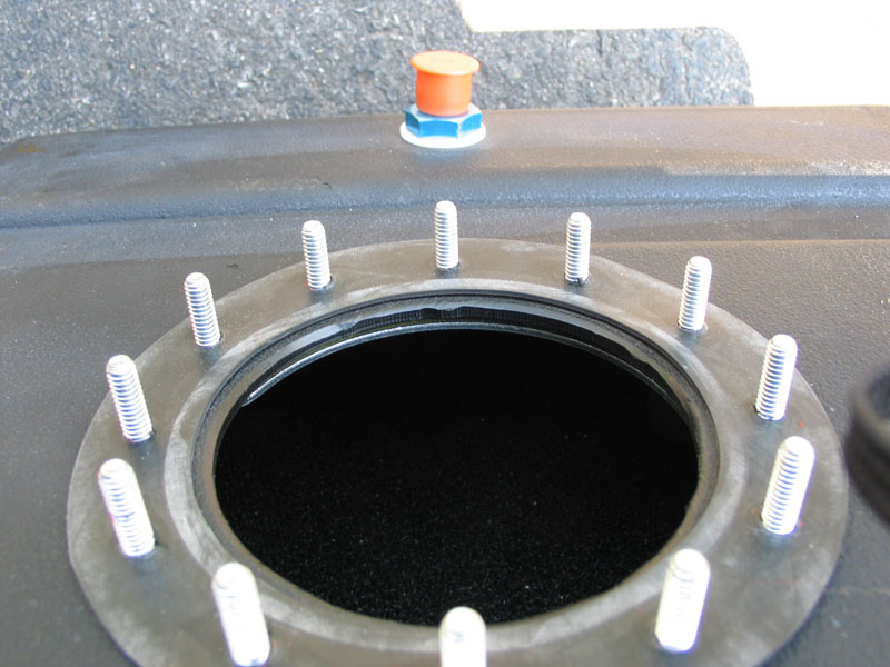
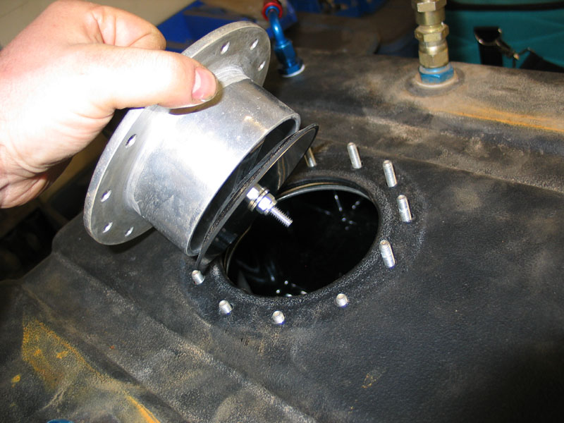
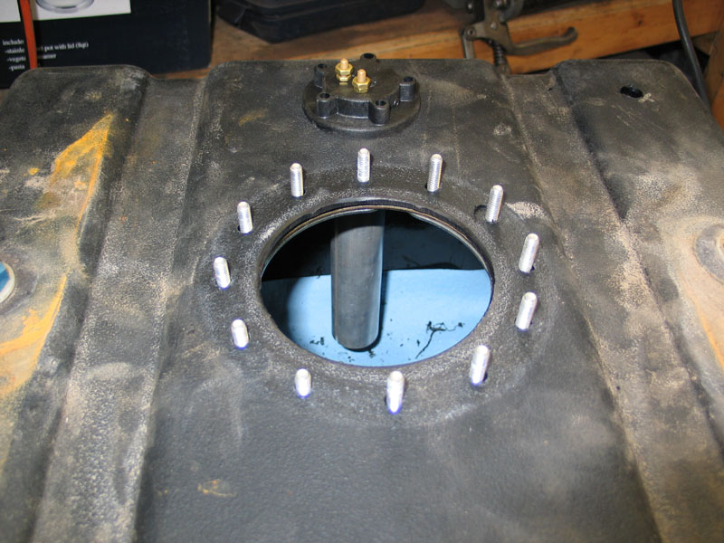
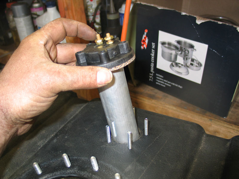
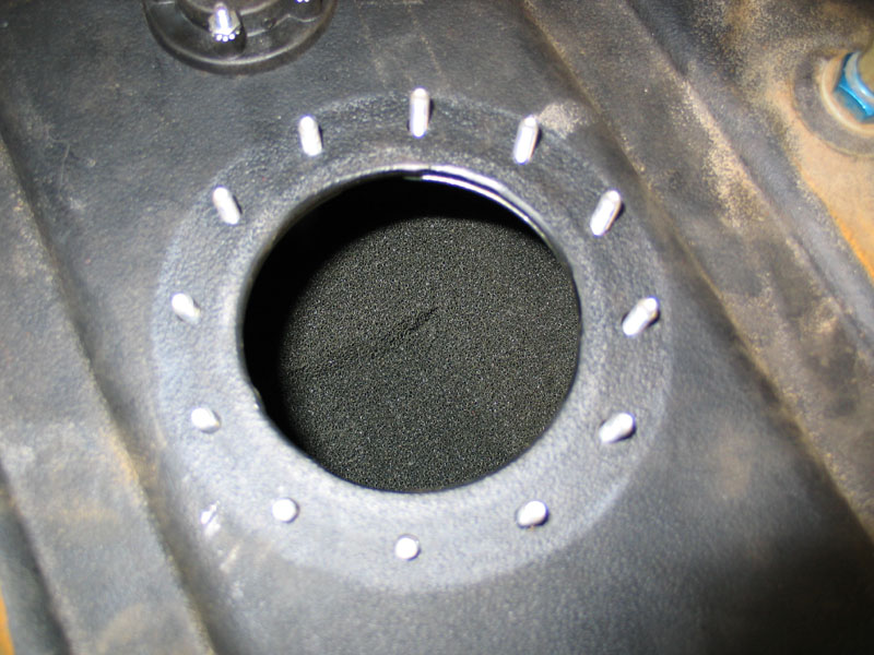
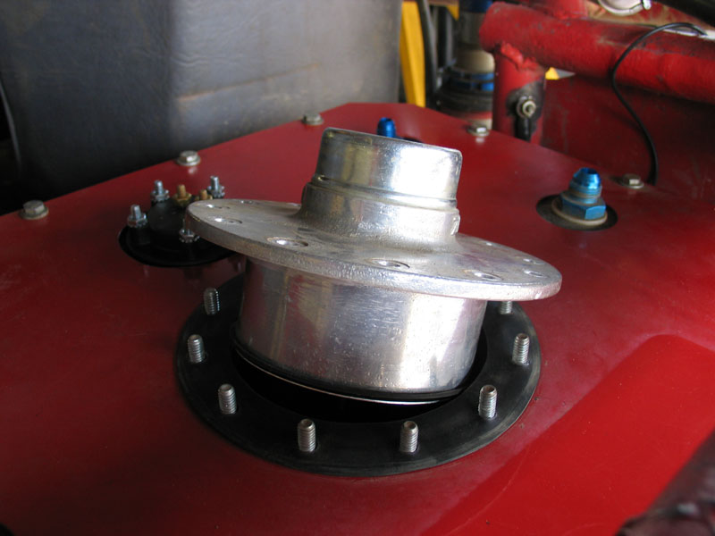
Let's take a look at it. If you remove the 12 nylon locking nuts and plastic washers that attach the filler neck, you can remove it and see inside the cell. There are two -8 male AN connections, seen on either side of the main opening. One is the fuel pickup and the other the vent. I don't know if it's an industry standard or not, but on my cell, the little orange plastic cap covered the fuel pickup, and the blue cap covered the rollover valve / vent. More details on these shortly. |
|
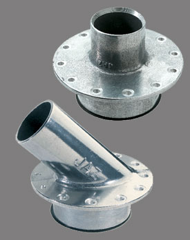
Filler necks are available in a wide variety of styles from straight and 45° to recessed. Some are designed to be used with remote fill hoses (normally mounted on the fender) and some are filled right at the tank. I chose the 90° "fast fill" filler neck shown at top left, on the recommendation of Dave at PolyPerformance. It's a cast-aluminum piece with 12 bolts for a secure, leak-free mounting and features a twist-lock cap. According to Dave, these style filler necks, in both straight and 45° ,are much less prone to leaking than the common D-ring bail handle style. In practice I have found the filler to be sturdy and leak free, and holds the gas pump nozzle nicely when filling up. The twist-lock cap is non-vented and has a nice secure feeling action but is not lockable and is not attached to the neck or tank (so watch where you set it after removing it!). |
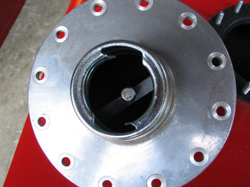 |
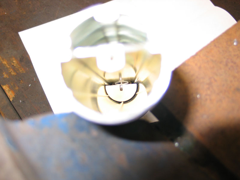
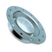
Most importantly, especially for those of us who spend a good portion of our day on our sides or lids, the filler neck comes with a spring-loaded flapper valve for rollover protection. |
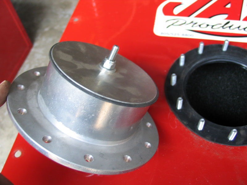 |
Spring pressure holds an aluminum disc and rubber seal against the bottom (in-tank) end of the filler neck so that fuel cannot leak out.
|
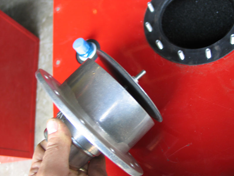 |
When filling the tank, the pressure of the fuelling nozzle opens the flapper to allow fuel in. |
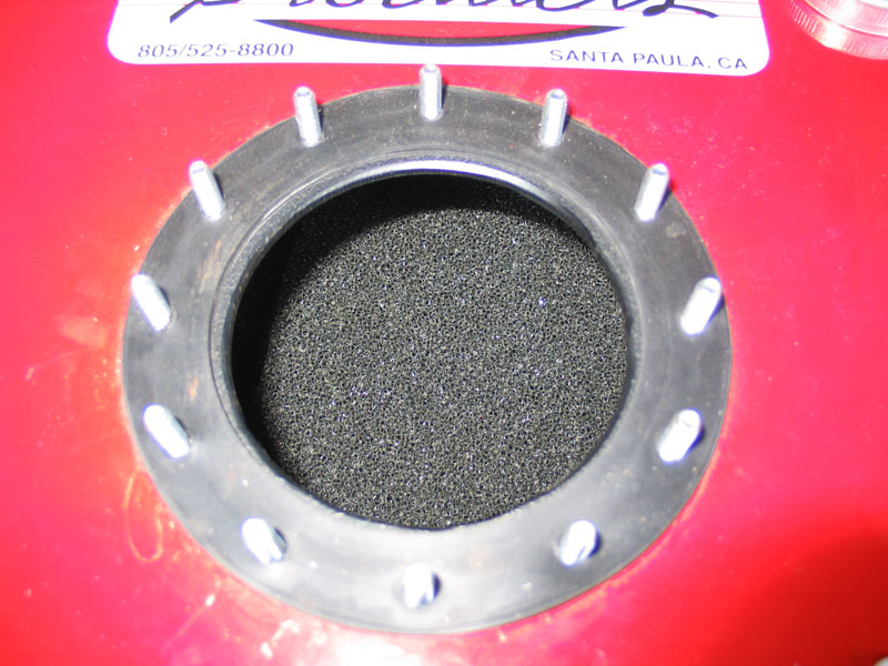 |
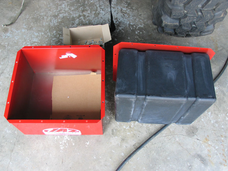
You can order this style, or any other fuel cell, with or without foam. The purpose of the foam is to prevent fuel sloshing. It was originally designed for use in aircraft that store the fuel inside tanks in the wings. As you can imagine, it wouldn't do to have large quantities of fuel sloshing around the wings of an aircraft in flight, drastically altering the weight and balance. As such, the foam is the most effective form of baffling to prevent fuel from sloshing. This can be a distinct advantage in an offroad rig used at steep angles, especially when the tank is less than full - not only for weight and balance, but also to reduce the chance of the pickup starving for fuel. |
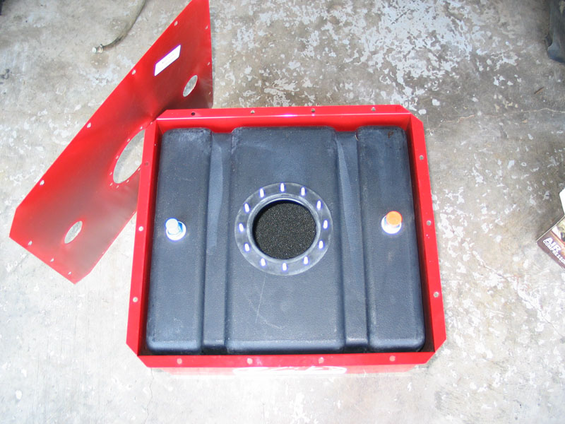 |
The steel box protects the fuel cell, makes it easy to mount, gives you a "double-wall" between the gas and occupants / gear, and protects the poly fuel cell from sunlight / UV. The poly liner or "tank" itself is much more resistant to cracking or bursting than a metal tank, even under crash conditions. It is also easy to drill, won't spark, won't crack or fatigue, and isn't electrically conductive. This style of fuel cell will never approach a custom aluminum unit for the ability to make best use of available space, but it does make a pretty convenient, safe, and effective package. I have heard complaints of the poly cell swelling due to UV and/or heat, but have not experienced this problem myself in the last two years. It's possible that installation, proper venting, mounting, and even environment play a part. Although you can buy them separately, I wouldn't recommend installing a bare poly tank in an offroad vehicle as you loose the safety and puncture resistance of the double-wall affect. |
 |
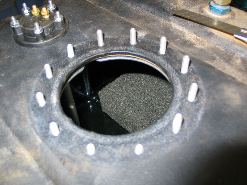
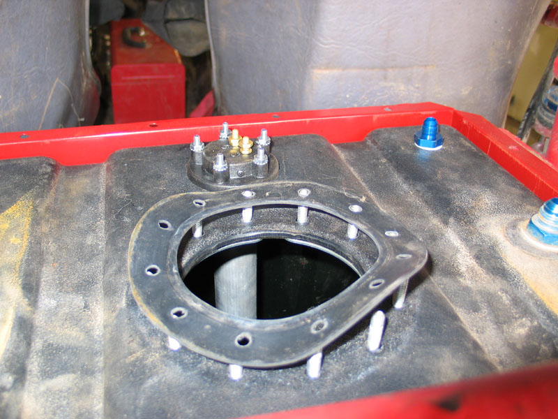
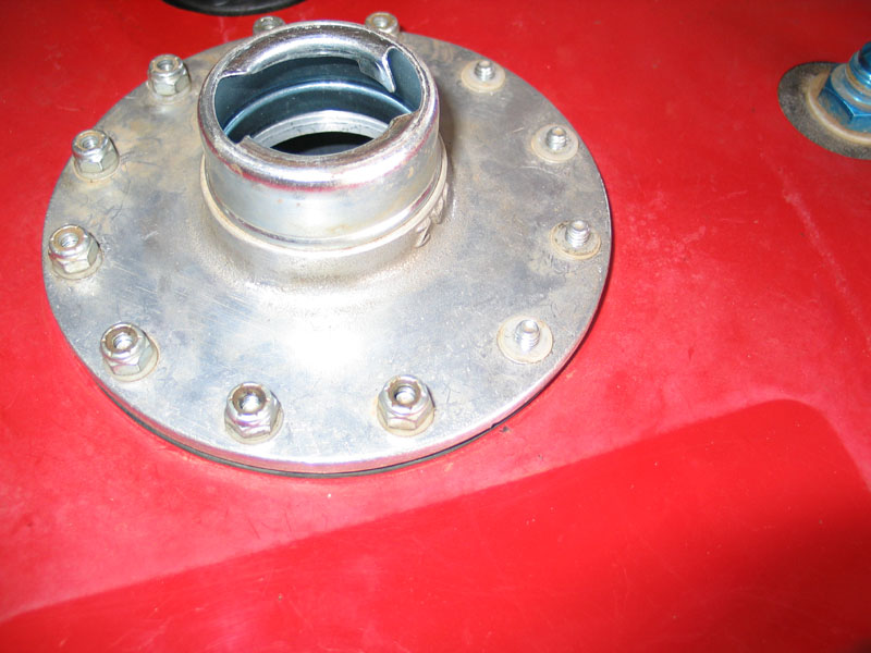
There are two rubber gaskets that seal the filler neck. One sandwiched between the filler neck and the steel lid of the box, as can be seen in the pic two photos up; and one sandwiched between the poly tank and the steel lid, as seen here. |
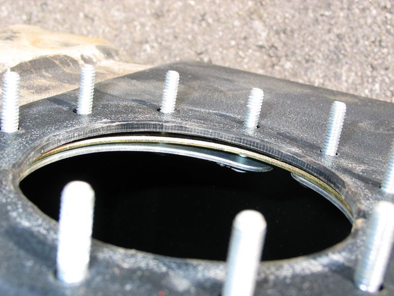 |
The studs that mount the filler neck are contained on two semi-circular rings, inserted from the inside of the tank. |
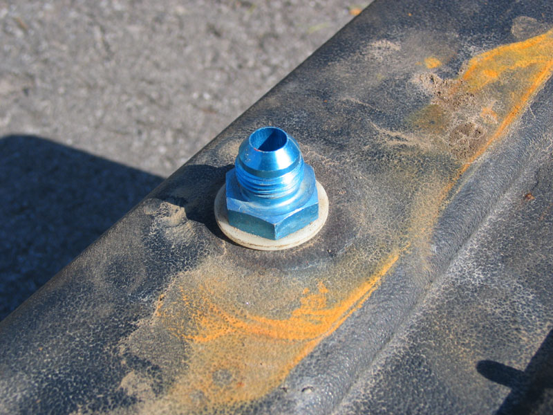 |
As mentioned, the fuel pickup connection is a -8 AN male thread. AN connections use a 37° flare to seal, the same as JIC hydraulic fittings. Also, remember that the "dash number" is the number of sixteenths of an inch of the ID of the fitting. Thus, a -8 fitting has a bore of 8/16" or 1/2". The fitting is simply an aluminum bulkhead fitting that sandwiches the poly tank between two plastic sealing washers. |
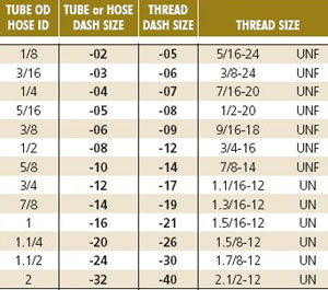 |
When matching AN fittings, just make sure not to confuse the -AN size for the tube (or bore) with the -AN size for the threads. Here's a little chart to help you keep it straight. The vast majority of fittings, and I think virtually all fuel fittings in AN sizes, are sold with reference to the -AN size of the tube, hose, or ID / bore of the fitting. |
 |
The in-tank side of the fitting simply has an "AN to hose barb" swivel hose-end connected to it, and a length of rubber fuel hose for the fuel pickup tube. |
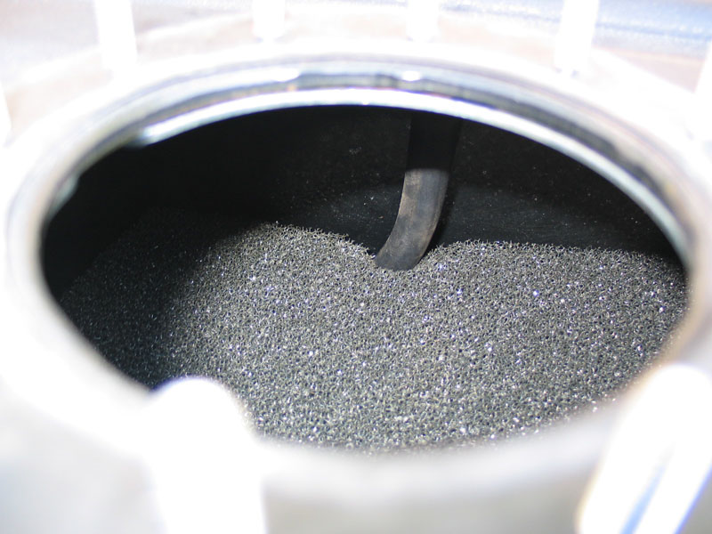 |
The pickup tube is wedged between the foam and the side of the tank. |
 |
And if we remove the foam we can see it terminates in the corner of the tank. There are countless threads on the internet about fancy pickups and weighted swinging assemblies and multiple pickups and things that look like bats, and sumps, and all sorts. I simply installed the fuel cell at a very slight angle both fore-aft and left-right so that the corner with the pickup tube (in my case, the left rear corner) would be the lowest point on level ground. Combined with the foam and keeping a reasonable level of gas in the tank, I have yet to have a fuel starvation problem at any angle with either carb or TBI. |
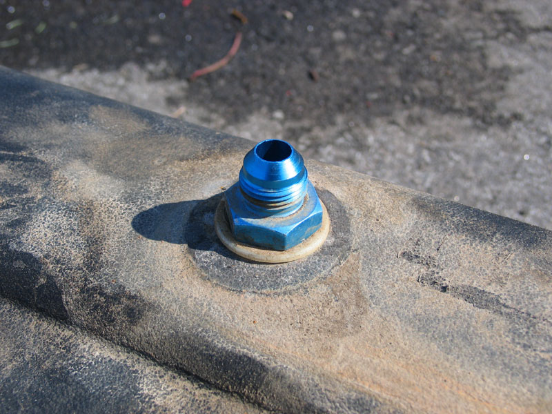 |
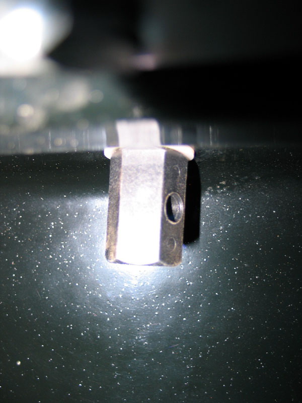
The other male -8 AN fitting is the vent. In its simplest form it is just an open hole between the tank and the atmosphere. Obviously, any fuel tank must be vented to atmospheric pressure for two reasons. First, to allow for the expansion and contraction of the fuel and vapour inside the tank that occurs with changes in temperature. Second, air must be allowed in as fuel is used, and air must be allowed out when the tank is refuelled. Of course, in practice, if this connection is simply an open hole, fuel will spill any time the rig is at a steep angle or rolled over - which in my case is a lot! As such, the fitting shown here is a tip-over valve, also known as a rollover valve or vent. There are several different styles available, depending on your needs, but they all work on the same principle. |
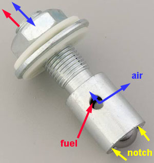 |
This particular tip-over valve has a standard threaded connection instead of an AN connection. However, it clearly shows how the valve functions. Air & fuel vapours are able to freely travel back and forth through the hollow threaded stem and out the small hole in the side (blue arrows). When the vehicle tips over, the ball seen at the lower right, drops into a tapered fitting inside the valve and effectively seals off the opening. There are a couple of problems with this design though. First, the vehicle must be completely upside-down for the ball to effectively seal in the valve - this means fuel can still leak out of the small holes on the side when the rig is on its side or a steep incline (red arrows). Another problem is, if fuel is ever forced into the small hole in the side (either by internal pressure or when the vehicle is on its side), a small amount will sit trapped on top of the ball and leak out the vent line the next time the vehicle tips to one side. JeepinDoug has an ingenuous solution: he takes a small jeweller's file and files two small notches in the swage that holds the ball captive at the bottom of the valve (yellow arrows). This way, any fuel trapped in the valve can drain back into the tank. |
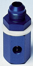 |
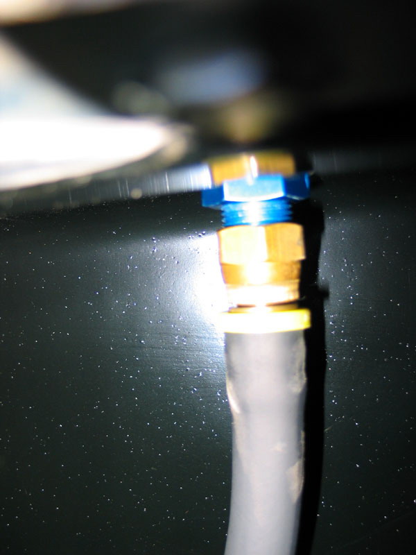
This is the style that came installed in my tank. It works the same as described above, except that it has an AN connection for attaching the vent hose. It is installed in the tank by sandwiching the tank between the two white plastic sealing washers. However imperfect the design, any fuel cell should have a tip-over valve installed for the vent. If you don't have one, they are cheap, and easy to install using the procedure I outline a little later for adding a fuel return-line fitting. This particular style is available from Summit Racing as p/n SUM-G3114. |
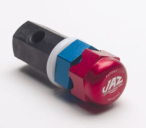 |
You can also get them with a built-in little filter cap on the top. This particular model is available as Summit p/n SUM-220020. However, I don't recommend this style, as there is no provision for attaching a vent hose, which is critical, along with proper vent hose routing, in solving the problem of fuel leaking out when the rig is on its side. More on vent hose routing a little later. |
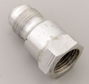 |
If you already have an AN fitting in your tank for the vent, but it doesn't have a built-in tip-over valve, you can add one in-line on top of the existing fitting. This model is available as p/n RCI 7021A. |
 |
This is what my valve looks like from inside the tank. |
 |
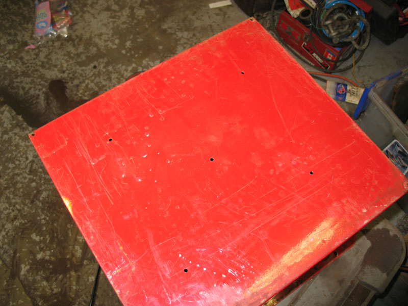
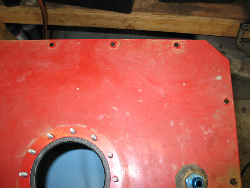
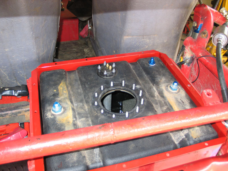
Back to the tank itself. This shot shows the simple arrangement of the poly tank inside the steel box. Notice the incomplete paint/powdercoat job on the inside of the box and also the piece of cardboard that was put there presumably when the thing was assembled. I presumed the cardboard was intentional and served as some kind of abrasion guard or padding between the poly tank and the steel box. This would turn out to bite me in the ass. |
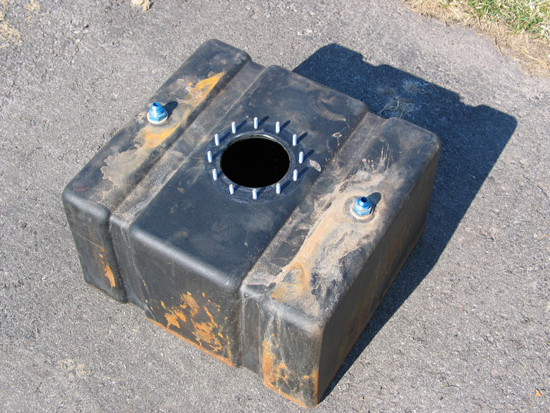 |
Fast forward two years of abusive use and I have removed the poly tank to add a fuel-level sender and a proper EFI return line (I has previously T'd the TBI return line into the vent, which works OK, but completely negates the tip-over valve and, in-fact, pumps fuel out the vent line in a rollover). The poly tank is in great shape... |
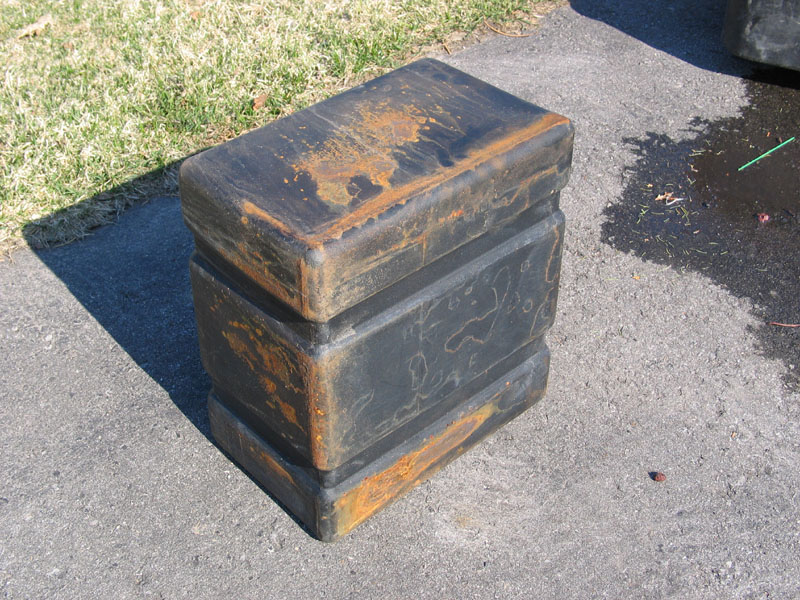 |
...but has some nasty corrosion stains transferred to it. |
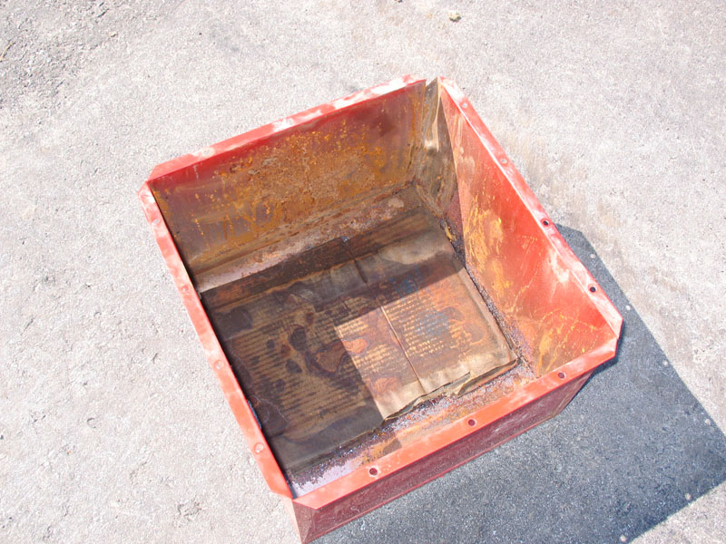 |
From this mess! The combination of incomplete paint inside the steel box, off-road conditions, tiny drain holes, and that ridiculous piece of cardboard acting: one, as a sponge to hold moisture inside the box; and two, to break down and effectively clog the tiny drain holes; has created a serious corrosion problem. I'm glad I took the cell out when I did instead of noticing the problem only when the box disintegrated! |
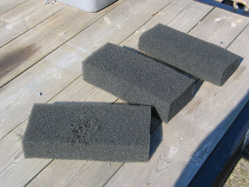 |
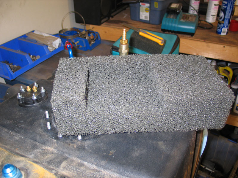
In order to work on the cell, I also had to remove the foam from the inside. As you can see, one of the pieces seems to have some damage. Was this the dreaded foam breakdown I had read so much about? |
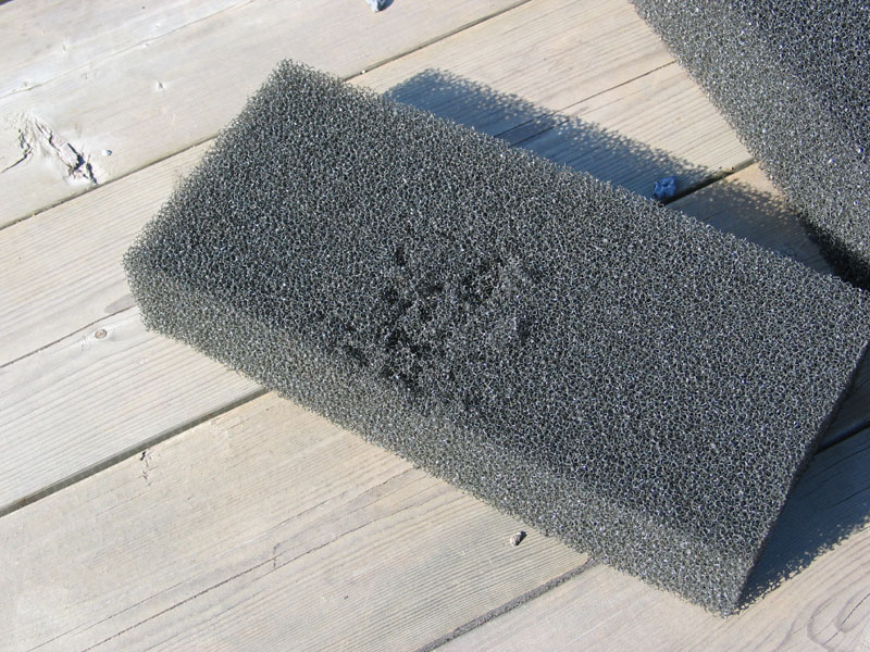 |
Close-up of the damaged foam. |
 |
I don't think the foam was breaking down chemically. In fact, I found that the damaged area was confined to the piece of foam directly below the filler neck, and when the flapper was opened during fill up, the sharp end of the excessively long bolt simply gouged the foam. Poor design! |
 |
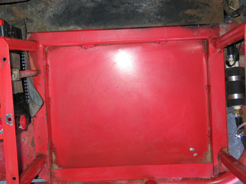
First step in the recovery process was to drill five extra, decent-sized, drain holes in the bottom of the box and enlarge the original pin-holes that passed for drain holes, located one in each corner. |
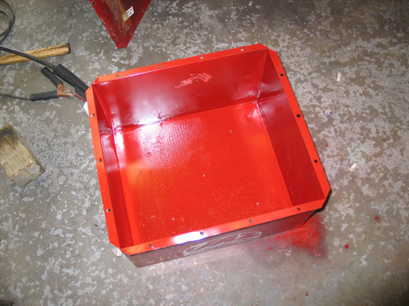 |
Next I cleaned the box with the old wire wheel on a grinder and painted it. |
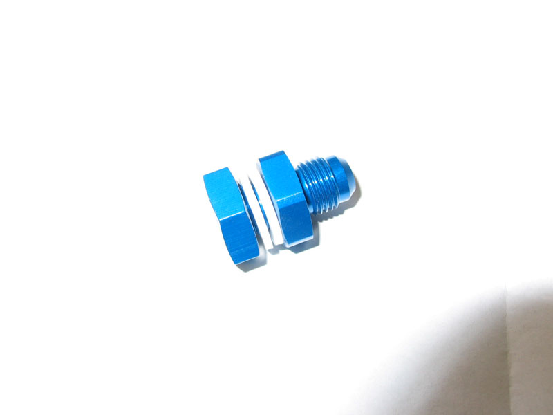 |
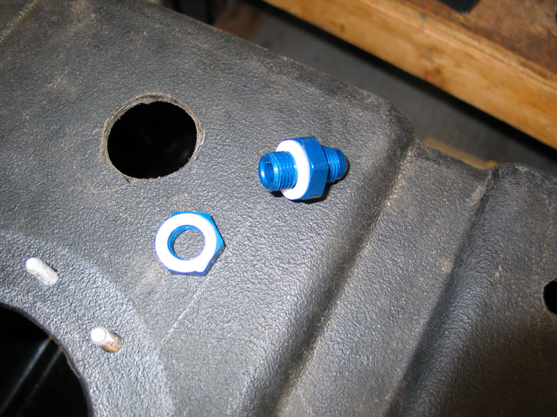
OK, so the first thing I needed to do was add a new bulkhead fitting for the TBI fuel return line. This is a picture of the fitting, it comes with the nut and two plastic sealing washers. They are available in different size, I chose -6. The complete part number and description is: SUM-220682: Fitting, Fuel Cell, Male Bulkhead, -6 AN, Aluminum, Blue Anodized. |
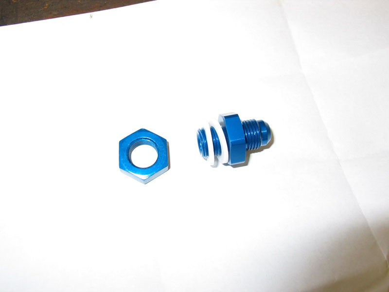 |
The nut and one of the washers go inside the tank and the fitting and other washer go on the outside. |
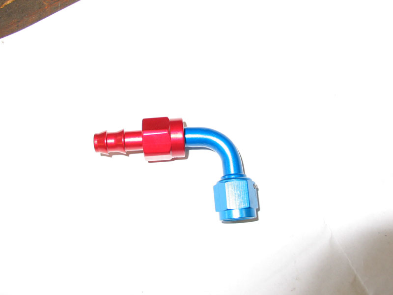 |
In order to connect the fuel return line to the bulkhead fitting, I ordered this 90° hose end: SUM-220711: Fitting, Hose End, 90 Degree, -6 AN Hose Barb to Female -6 AN, Aluminum, Red/ Blue Anodized. The fuel line pushes onto the barbed end and the female threaded end screws onto the bulkhead fitting. |
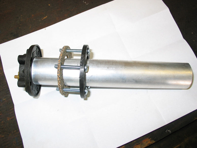 |
Tired of tapping, dipping, or guessing at the fuel level in the tank, I also decided to install a fuel level sender. I chose the tube style for its compactness and ease of installation. They are available in different levels of resistance to match the gauge you will be using. They are also available in 8.5" or 11.5" lengths. Since my tank is about 10" deep, I chose the 8.5" long model. SUM-290180: Sending Unit, Fuel Level, Tube-Type, 0-90 Ohm. |
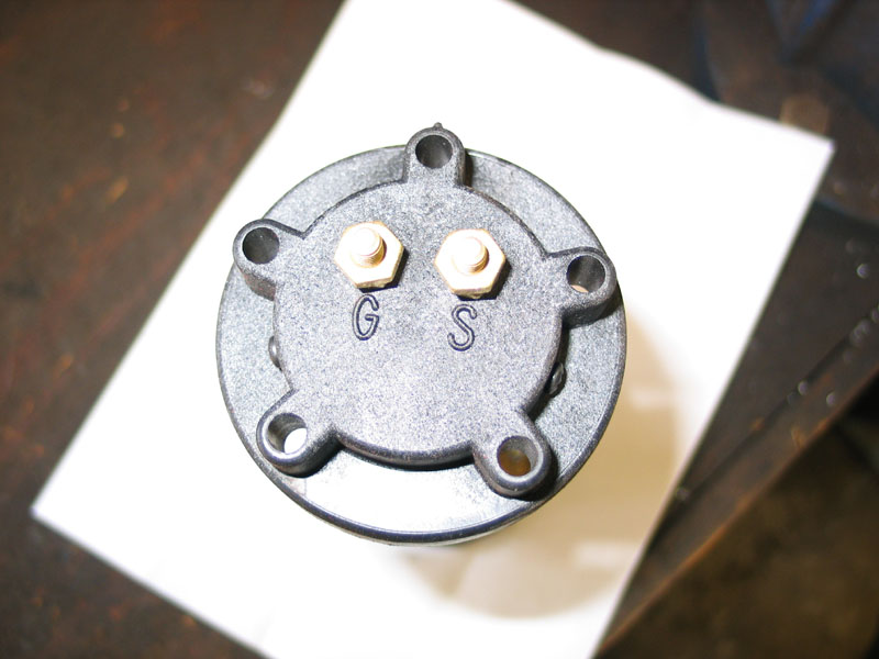 |
There are two electrical connections on the unit: G goes to chassis ground. S goes to the "signal" connector on the gauge. |
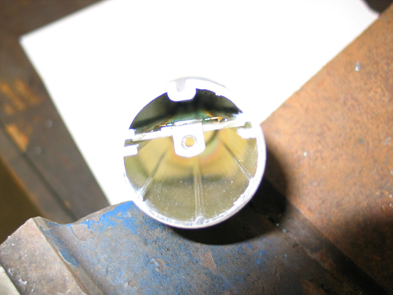 |
Inside the tube you can see the copper wire that provides varying resistance depending on the position of the little plastic float... |
 |
... and the plastic float captive in the tube. |
 |
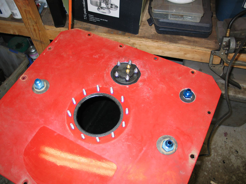
Lay out the positions for the new attachments on the tank itself. Make sure you retain adequate clearance from other fittings, the sides, and the mounting strap grooves (that aren't actually used with the cell mounted in the steel box). |
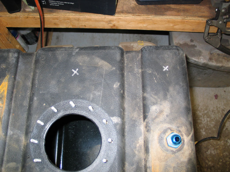 |
Mark the positions with a permanent marker. |
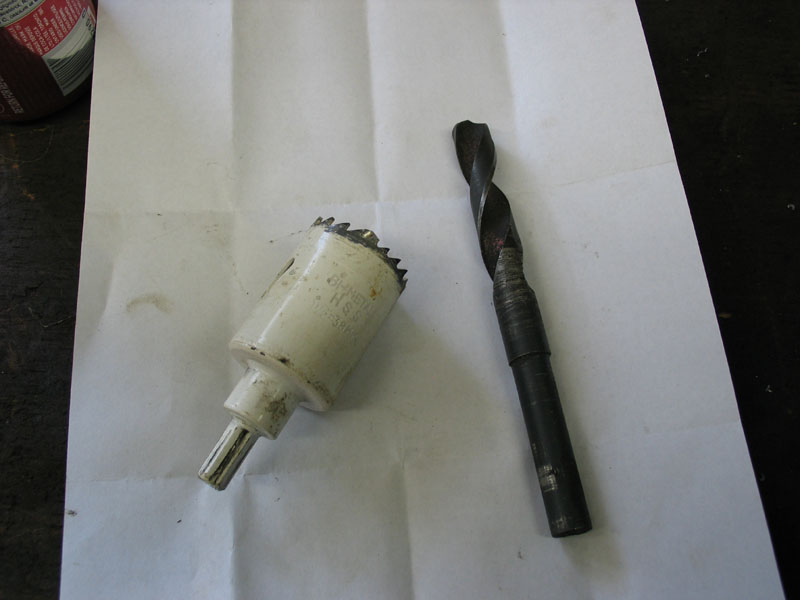 |
You will need a 9/16" drill bit to make the hole for the -6 bulkhead fitting, and a 1.5" hole saw to make the hole for the fuel level sender. |
 |
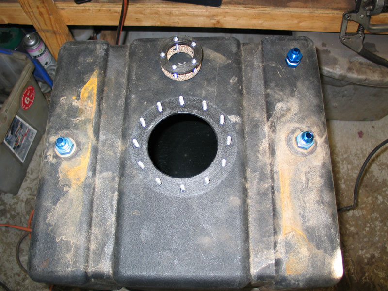
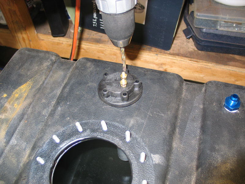
You need to drill the holes through both the steel lid, and the poly tank. Installing the lid over the 12 filler neck studs and drilling both at once will keep the holes aligned. Notice the blue shop towel placed inside the tank to catch any shavings that fall inside the tank during the drilling. |
 |
Once the holes are drilled, remove the steel lid and set it aside (you will have to enlarge its holes later). Then carefully de-bur the holes in the poly tank with a small file. Be careful not to enlarge the holes, but make sure the edges are all smooth and free of any stray bits of plastic. Here I am test fitting the sender in its new hole. You can see the shavings inside the tank. |
 |
To install the bulkhead fitting, first separate the nut and one of the washers... |
 |
...then hold the washer and nut inside the tank and tighten the fitting into them, sandwiching the tank between the two washers. Tighten securely but don't overdo it - remember you're only working with plastic and aluminum parts. |
 |
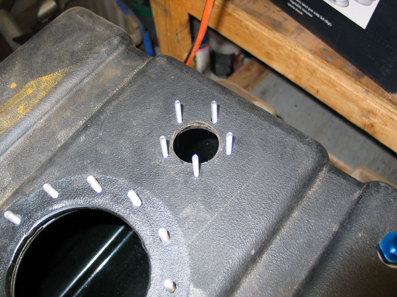
Insert the fuel sender into its hole, and use it as a template to drill the five 7/32" mounting holes. |
 |
Slip the cork gasket onto the sending unit. |
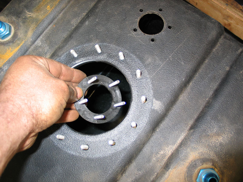 |
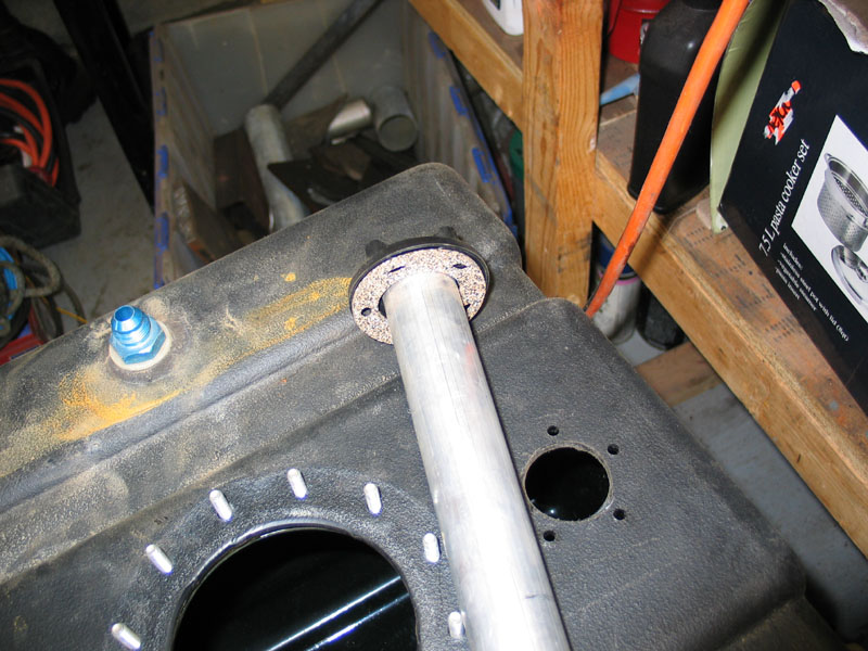
Insert the sending unit's retaining ring into the tank... |
 |
...and fit it into place in the five mounting holes. |
 |
Insert the sender... |
 |
...and install and tighten the five mounting nuts. You will also have to enlarge the holes in the steel lid to fit over the bulkhead fitting and top of the fuel level sending unit. A smart person would have realized this earlier, and when drilling the initial holes with the lid and tank together, have drilled only a small pilot hole through both, and consequently been able to use a larger hole-saw to drill the larger holes in the lid resulting in neat and perfectly centred clearance holes. I, however, did not and therefore had to try and enlarge the holes with a rusty old jigsaw with the wrong type of blade, sawing away with the thin, unsupported lid flapping away like a mad creature possessed! |
 |
After thoroughly cleaning the inside of that tank of any debris, it's time to re-insert the foam. I used a sharp utility knife to trim a clearance slot for the bolt on the filler neck flapper valve so that it won't chew up the foam any more. I also trimmed the length of the centre piece to allow clearance for the fuel level sender. |
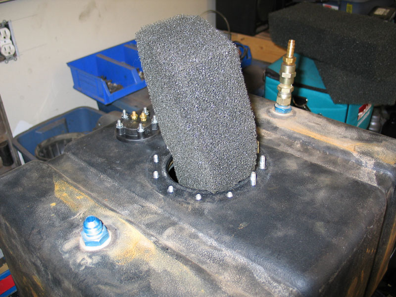 |
Insert the foam into the tank. |
 |
Clearance for the bolt on the filler neck flapper valve. |
 |
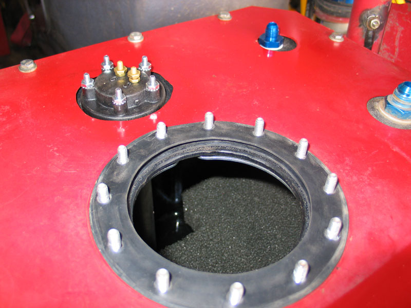
Foam and sending unit installed. |
 |
Next, reinsert the ploy tank into the steel box. |
 |
It's a tight fit and keeps everything secure. |
 |
You will have noticed that the box and its lid have multiple bolt holes. These holes are for joining the lid to the box and for providing some lateral and fore-aft support to the fuel cell. They are NOT designed to carry the entire weight of the full fuel cell. I built a small frame in which to mount the fuel cell. |
 |
The bottom of the fuel cell sits on the frame, supporting the weight. |
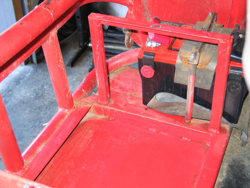 |
The stanchions give lateral support and have bolt holes that line up (sort of!) with the holes in the fuel cell, so everything can be securely bolted together. |
 |
The external in-line fuel pump is located below and beside the fuel cell frame. |
 |
With the fuel cell set in place in its frame, it's time to reassemble the lid and filler neck. |
 |
Install one of the rubber seals directly onto the poly tank. |
 |
Set the steel lid in place. |
 |
And install the other rubber seal. |
 |
Install the filler neck, followed by the 12 plastic washers on the mounting studs. |
 |
Then install and tighten the 12 nylon lock nuts |
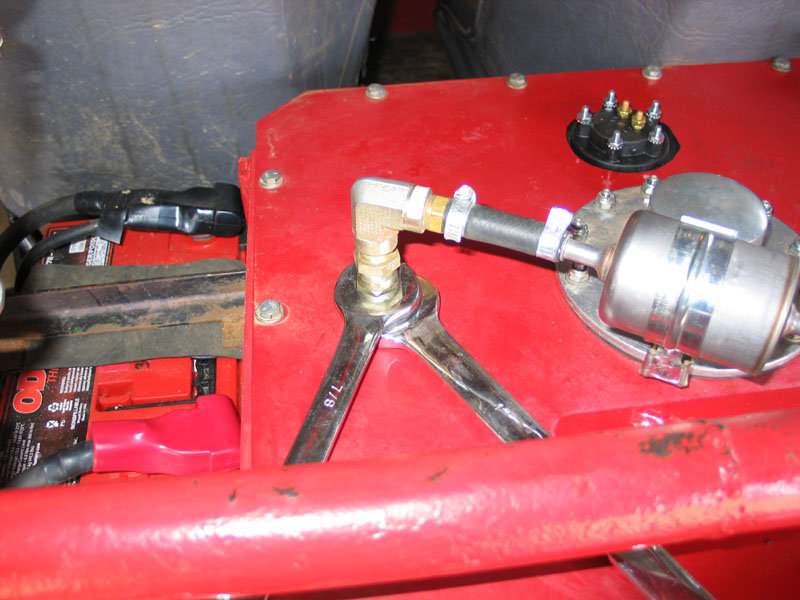 |
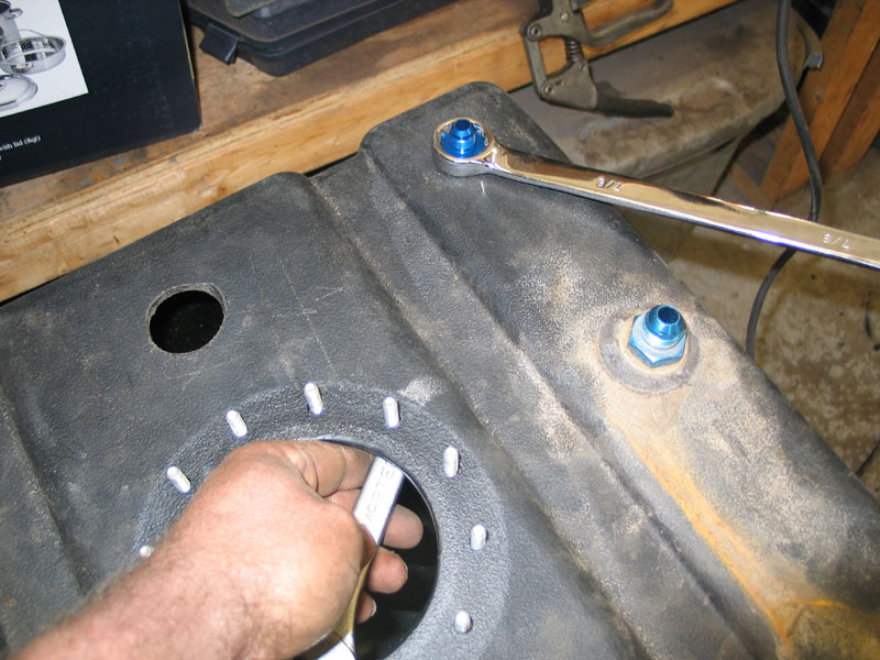
Next, connect the fuel line, fuel return line, vent hose, and electrical connectors to the fuel cell. Always make sure you hold the bulkhead fittings securely with a wrench when tightening fittings. |
 |
Clockwise, from top centre:
|
 |
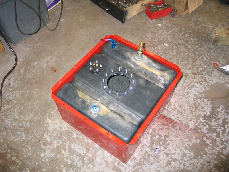
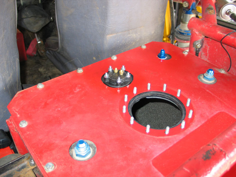
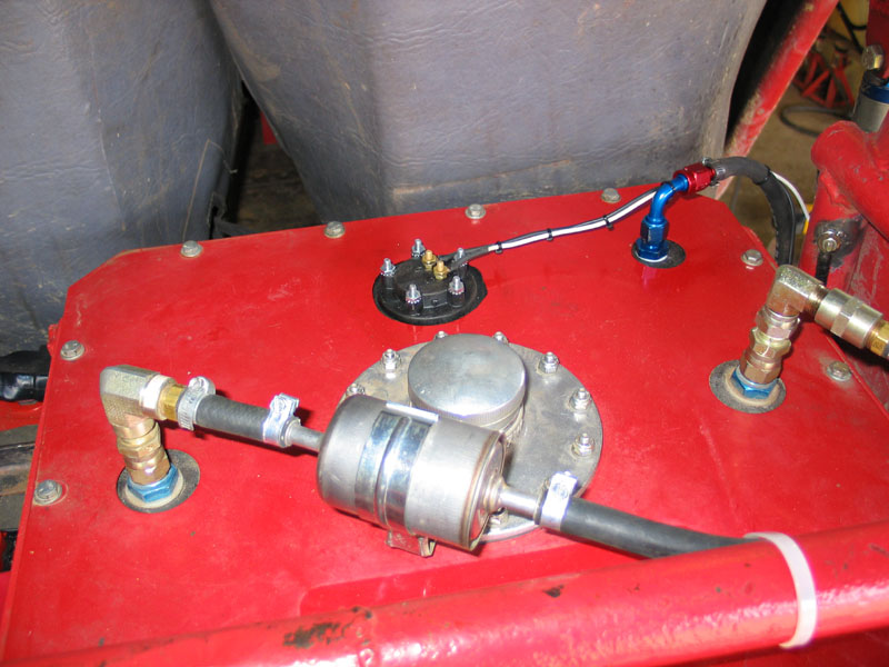
Complete, installed fuel cell. |
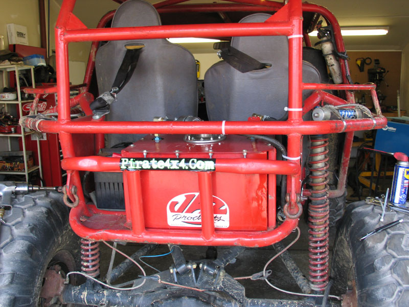 |
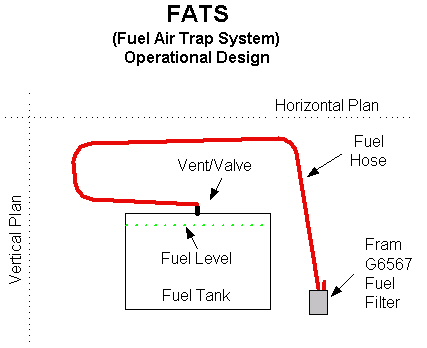
Complete, installed fuel cell. OK, we have just one issue left to solve - that of the leaking tip-over valve when the vehicle is vertical or on one side. The solution to the problem is in the routing of the vent hose. If you route the vent hose in a particular manner, you can ensure that a length of the hose will always be above the level of the tank, regardless of the position or orientation of the rig. In this manner, a liquid/air trap is created, similar to the one under your kitchen sink that prevents sewer gas from backing up through the drain in the sink. |
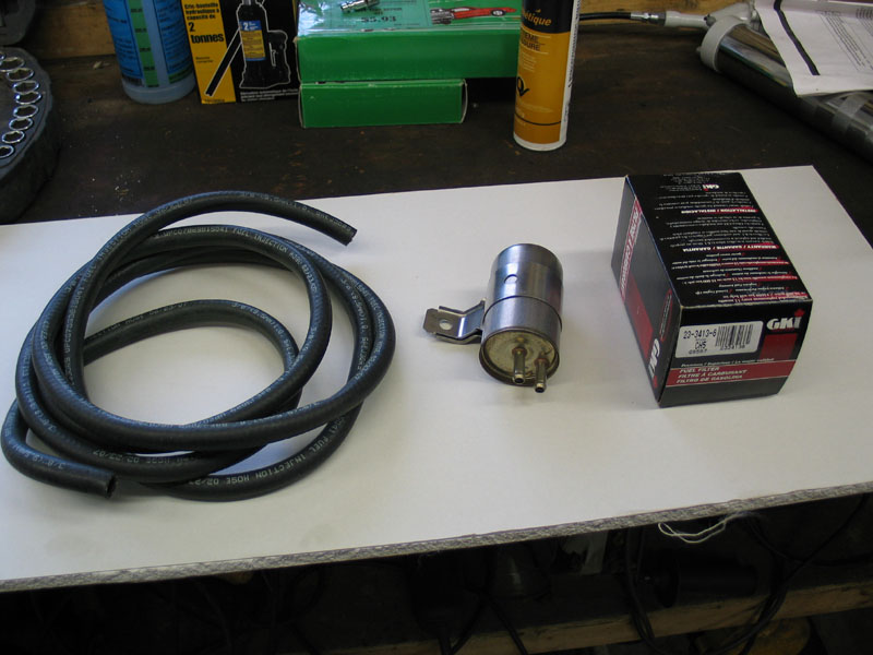 |
There are a couple of different ways you can accomplish this, with varying degrees of effectiveness and tidiness of install. I decided to copy the simple, elegant, and I think, brilliant plan first proposed by Frank Daless In the article where I first came across Frank's idea he does a great job of explaining the system and includes some great diagrams. I have duplicated some of his work here for clarity. The text that follows in italics are the words of Frank, for which he rightly deserves full credit. All you need are a few feet of 3/8 fuel hose and a particular fuel filter.
|
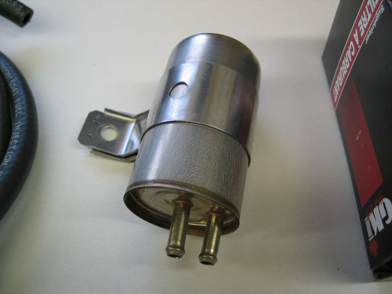 |
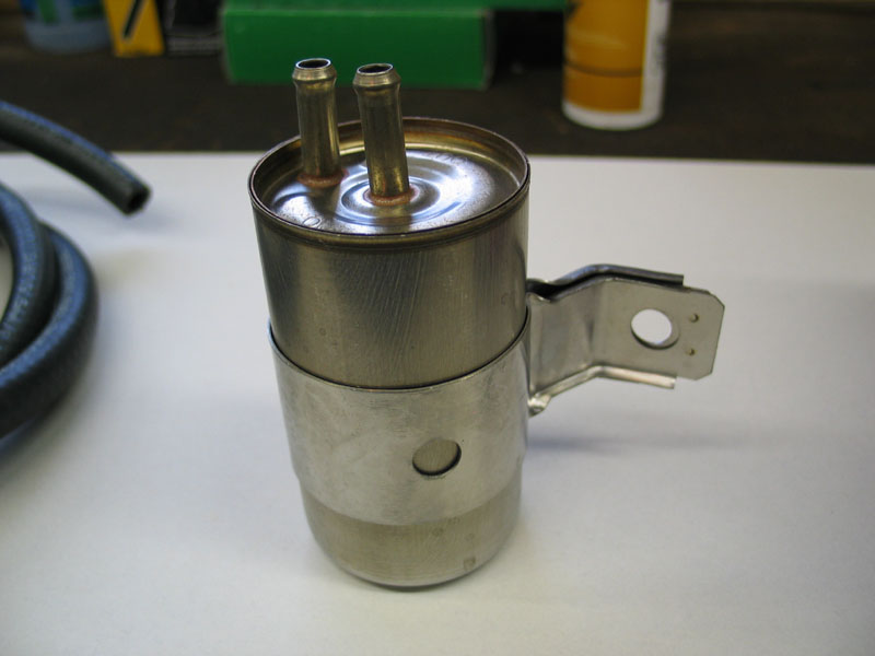
The fuel filter in question is a Fram G6567. It's key to the system because it has a reasonable volume and also has both the in and out ports on the same side, as can be seen here. Some other part numbers for this filter are: Wix: 33321 / Warner: G489 / Shell: F54617 / Quaker state: F54617 / Purolator: F54617 / NAPA: 3321 / Carquest: 86321 / Canadian Tire: 23-3413-6 / Baldwin: BF815 / Autopar : FE269 / AC Delco: GF681 |
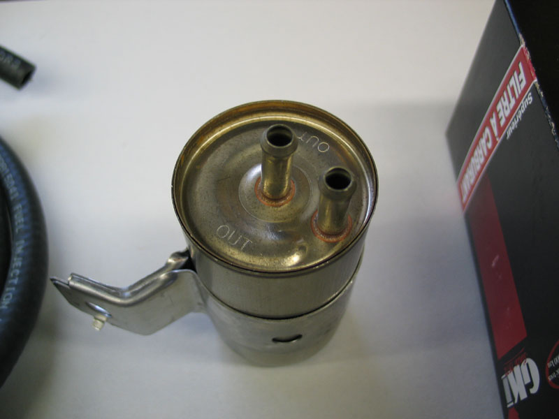 |
The application is: 89-90 5.2L V8 Dodge Dakota Vin Y 88-90 3.9L V6 Dodge Dakota Vin X 89-90 2.5L 4 Dodge Dakota Vin K As you can see, it has a handy mounting tab and at 4.72" high x 2.17" in diameter, it has enough volume to hold the fuel from 12 feet of 3/8" fuel hose. |
 |
As Frank explains it, the key to the system is the specific routing of the vent hose: Fuel Hose Routing |
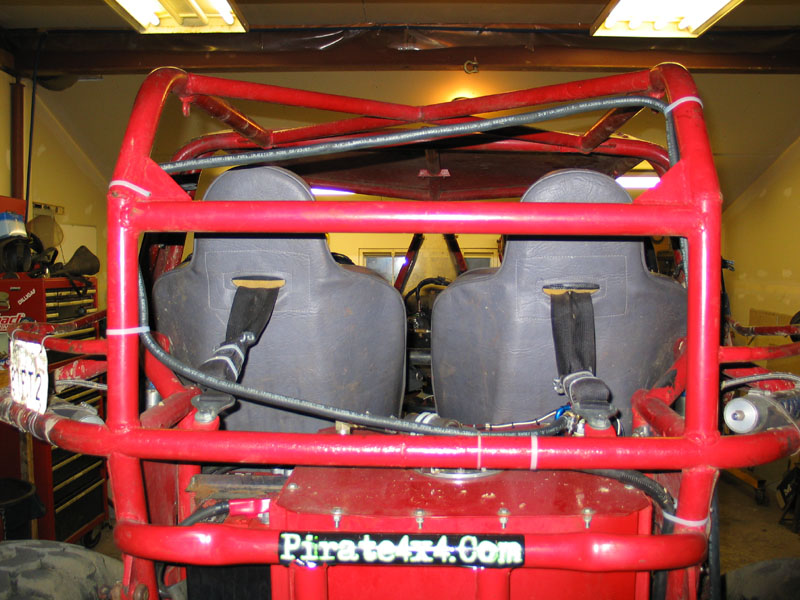 |
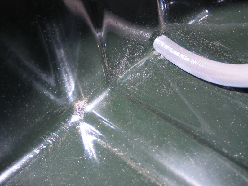
Here is a pic of the design employed on my buggy. |
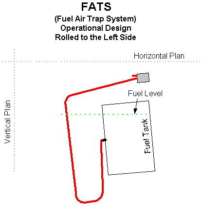 |
FATS Operations Let’s roll the vehicle over to the left, past 90 degrees and take a look at what happens. If the vent/valves leak fuel in this position, the fuel runs into the fuel hose attached to the vent/valve, but cannot exit to the environment because of the fuel hose routing, which forms the trap. The fuel level in the hose can only reach the vertical height of the fuel in the tank. (Physics says so.). When the vehicle is up righted any fuel that may or may not have gone into the fuel hose will flow back into the fuel tank via gravity and the slope of the hose routing. |
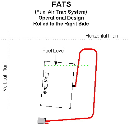 |
Here is another drawing of a vehicle rolled to the right. Again, the fuel, which leaks past the vent/valve, can only reach the height of the fuel level in the tank. When the vehicle is righted, the fuel in the hose will flow back into the tank. |
 |
Fuel Hose Termination Please note the FRAM Fuel Filter only comes into play during a full roll over. It is installed on the end of the fuel line to catch any fuel that may or may not be in the fuel lines. |
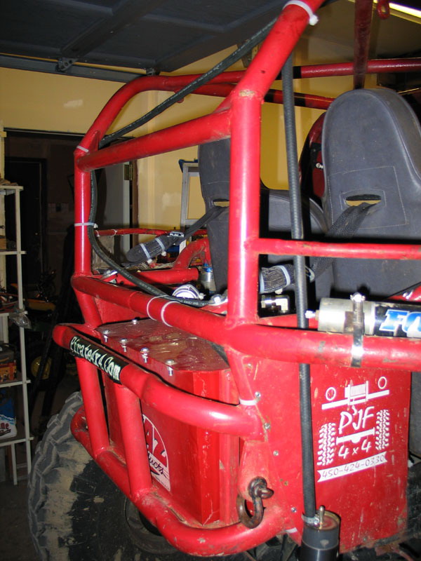 |
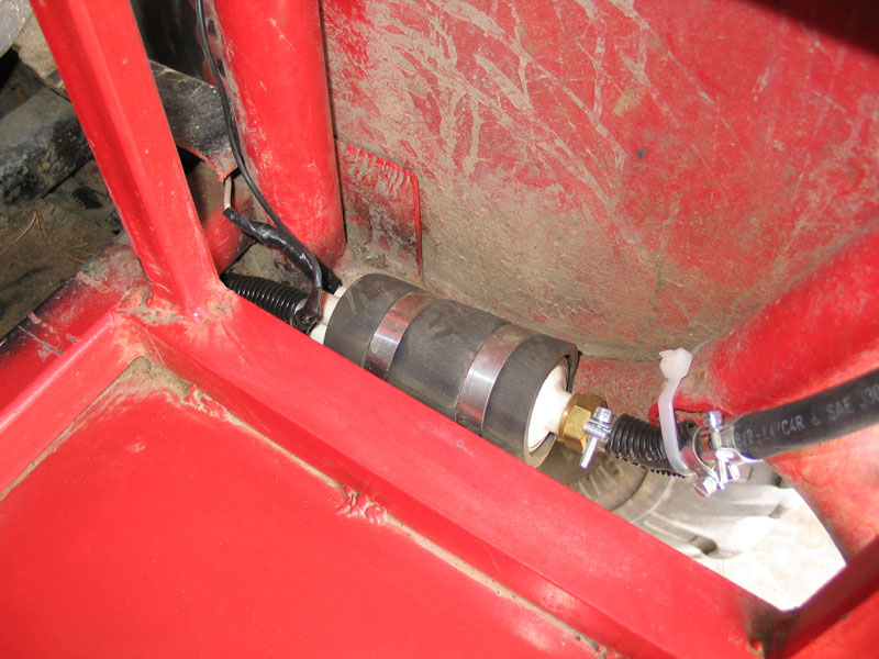
Here is a pic of the filter / catch can installed at the end of the vent hose in my buggy. The metal fuel canister comes into play if and only if all these situations happen. It will be essential to manually empty the catch can after a roll because if there is fuel in it, it will effectively block the vent hose (just like the sink trap blocks the venting of sewer gas into your kitchen/bathroom) and you fuel tank will no longer be vented. |
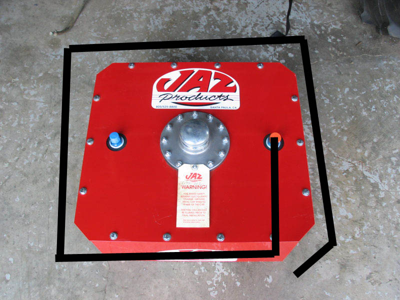 |
I haven't personally tested or verified it, but it seems to me that a similar effect could be achieved by routing the vent hose around the fuel cell and terminating it below the bottom of the tank in a manner similar to that shown at left. |
| The "bladder in a box " style fuel cell may not be the perfect solution for all applications, but it is a safe, convenient, and reliable setup that has worked well for me for a couple of years. Aluminum fuel cells also have their advantages, especially custom built units. When researching and selecting a fuel cell that will work best for you, it helps to talk with a vendor who has experience with the type of cell and type of rig you are considering. I consulted with Dave at PolyPerformance before buying my cell, as Poly have experience with a great number of different setups and carry a large selection of different styles of fuel cell, including: Fuel Safe, Gen-Right, and Jaz Products. | |
 |
Sources: PolyPerformance Summit Racing |
|