 |
MEFI 4 Tech
By Bill "BillaVista" Ansell |
IntroductionGeneral Motors Powertrain Introduced it's Marine Electronic Fuel Injection (MEFI) system in 1992. Since then, there have been several upgrades to the system. This article covers the fourth-generation of the GM MEFI system, known as MEFI-4. |
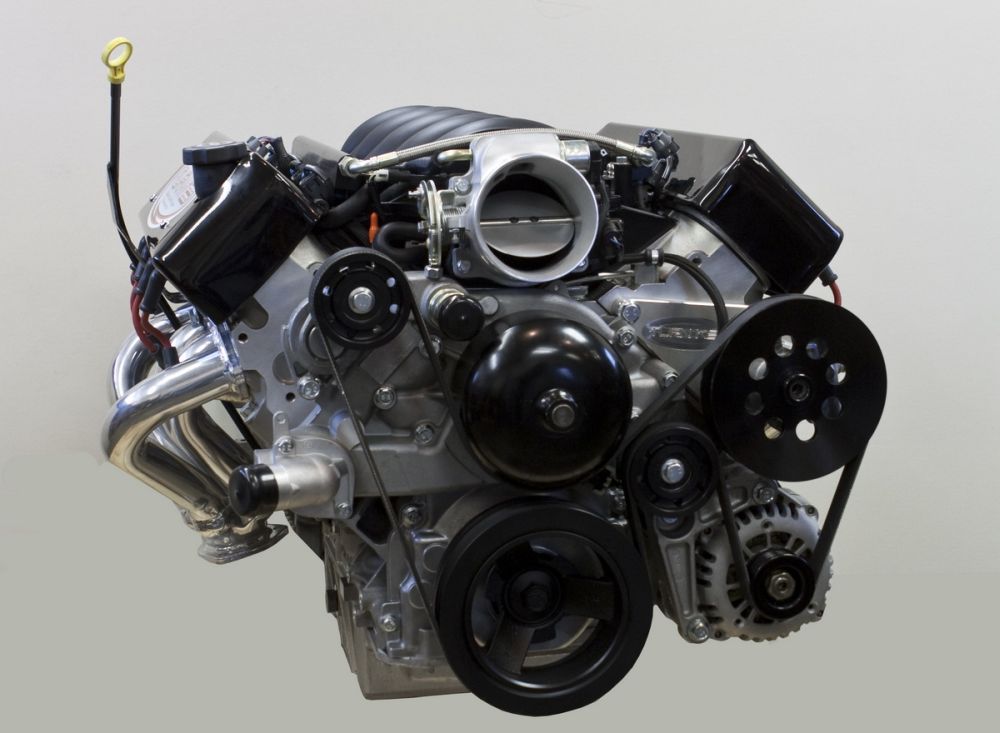 |
Fuel Injection BasicsWhether in a boat, car, or buggy, the fundamentals of the 4-stroke internal combustion engine haven't changed since its invention - it's still suck, squeeze, bang, blow; and the engine still needs just three things to run: air, fuel, and spark. How well it runs, and how much power it makes still depends on combining these three things in the right proportions at the right time. The more you step on the throttle pedal, the more the throttle blade opens, and the more air enters the engine. Feeding an engine the right amount of fuel is basically a function of engine load - the more load on the engine, the more fuel it needs. Spark timing is basically a function of engine speed - the faster the engine speed, the earlier in the "squeeze" (compression stroke) the spark must be fired. In today's modern EFI engines, fuel and spark delivery are controlled by a computer or Electronic Control Module (ECM). Fuel is delivered, or injected, directly into the cylinders by fuel injectors. Fuel injectors are nothing more than highly sensitive and accurate valves - they are supplied fuel by the fuel rail at a constant pressure, and have a calibrated orifice, or opening. The computer fuels the engine by telling the injectors when to "fire" (open and deliver fuel), and controls how much fuel is delivered by how long it tells the injector to stay open. Spark timing is similarly controlled by the computer. In the case of the LS2, which has individual ignition coils for each cylinder, the computer simply tells each coil when to "fire" and thereby create a spark across the spark-plug electrodes which, of course, ignites the fuel-air mixture in the cylinder and begins the "bang", or compression stroke, which is what makes power at the crank. Remember how we said that the amount of fuel required depends on engine load, and the spark timing on engine speed? It follows then, that the computer needs to know, or be able to measure, how much load is on the engine, and how fast the engine is turning. It gets this information from an array of engine sensors. With that information, it then "looks up" how much fuel to inject, when to inject it, and when to fire the spark for each cylinder in a set of pre-programmed tables (know as the "calibration") stored in the ECM's memory. Bottom line - the ECM accepts sensor information (inputs), then takes that data and looks up in its calibration tables, then sends signals (outputs) to control the engine, primarily to deliver the correct fuel and spark timing that the engine requires. Of course, the preceding explanation is a grossly over-simplified version, just to illustrate the basic principles. There are a host of other conditions and environmental factors, in addition to engine load and speed, that affect fueling and spark timing. Things such as temperature (of the surroundings, and of the engine), altitude, throttle position, whether the car is accelerating or decelerating, etc. all play a roll. In order to account for these conditions and deliver correct fuel and spark for all possible engine operating conditions, the ECM reads several other engine sensors and uses this data to "modify" the data it has looked up in the base calibration tables. There are different computing or calculation strategies used by different systems to accomplish this, the most common being "mass airflow", "speed-density", and "Alpha-N". Of these three, mass airflow is the most complicated, requires the most sensors, and relies heavily on a somewhat finicky and fragile air-flow sensor placed in the air inlet stream; it is commonly used in production vehicles but is not the best choice for rugged marine or off-road use. Alpha-N uses very few sensors and is little more than an electronic carburetor, relying primarily on engine rpm to decide how much fuel to add; it is normally suitable only for use in race cars that run at wide-open-throttle most of the time. MEFIThe GM MEFI-4 system uses speed-density calculation. It also has some basic differences from production road-vehicle fuel injection systems. |
|
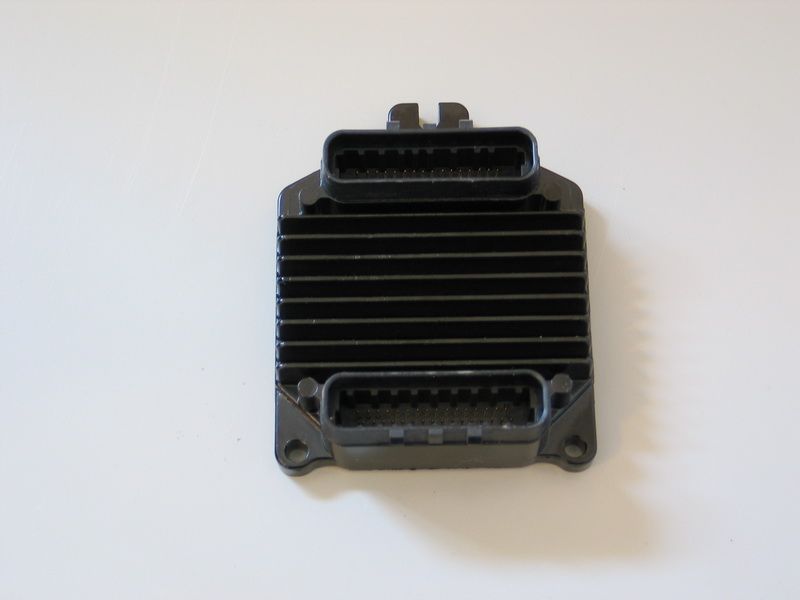 |
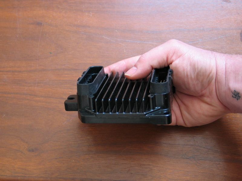
This is the GM-Delphi MEFI-4 ECM. It has two connectors and three mounting bosses. |
||||
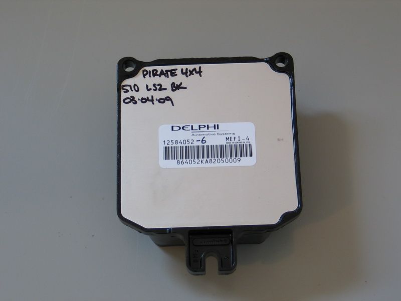 |
Back side of the ECM. Note the part number on the sticker. In this case "12584052".
|
||||
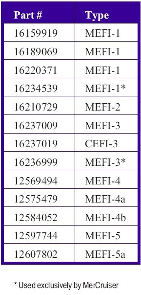
All MEFI ECM's have a part number like this that can be used to determine the "series" or "generation" that the MEFI system is, according to the following table:
|
|||||
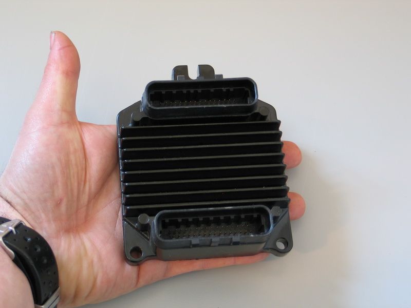 |
From the above table, we can tell that this particular ECM is a MEFI-4b Note how compact the MEFI-4 ECM is. |
||||
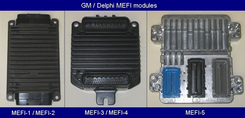 |
This picture shows what the other MEFI generation ECM's look like to help you identify them. | ||||
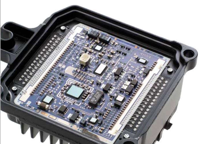 |
Inside the ECM. The MEFI-4 ECM is manufactured using a state-of-the-art, thick-film “hybrid” technology that forms the circuits by literally “printing” layers of conductive and nonconductive ink onto a ceramic substrate. The result is an extremely rugged and durable circuit board that can be mounted directly onto the engine if required, because it can handle very high temperatures and severe vibrations. |
||||
 |
Extensive use of “flip chip” integrated circuit technology The MEFI-4 ECM also "learns" as it is driven, fine-tuning its calibration / outputs in response to atmospheric conditions, engine condition, and driving style. |
||||
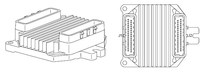 |
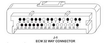
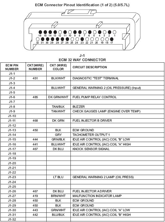
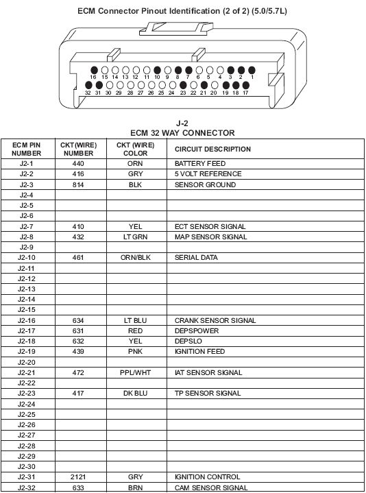
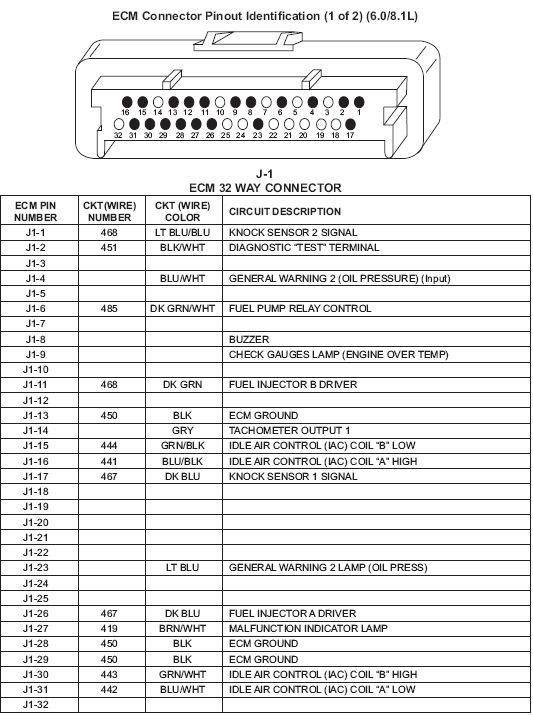
The ECM connectors are labelled J1 and J2, as shown in this diagram (click to expand). | ||||
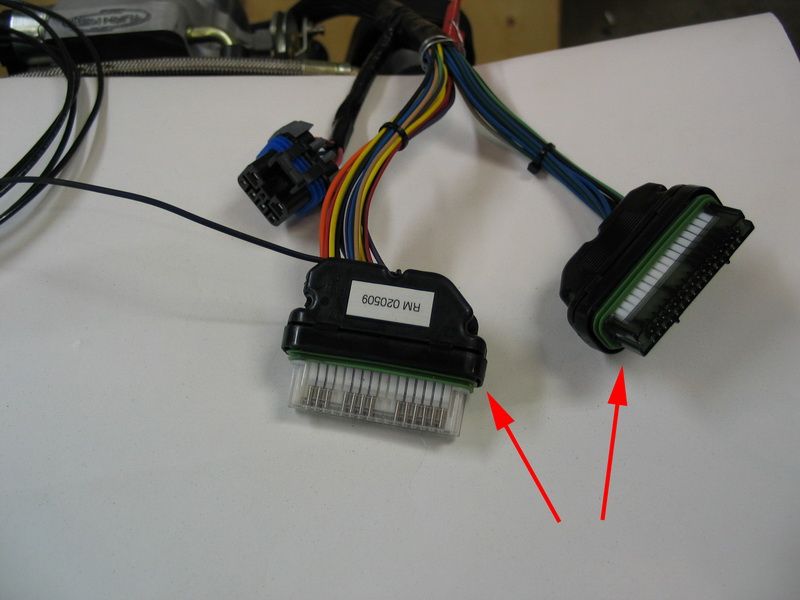 |
These are the wiring harness connectors that plug into the ECM, J1 and J2. They only plug in one way, with the clip to the outside of the ECM, and you can't plug them into the wrong sockets.\ However, each has 32 very small pins so you should verify the connection before plugging it in, and never force it, as damage to the pins or ECM can occur. Also, you should completely disconnect the vehicle's electrical system by disconnecting the battery ground cable before unplugging or plugging in the ECM connectors. Never weld on the vehicle with the ECM plugged in either. |
||||
MEFI-4 ECM Pin-outsHere are the pinouts for the MEFI-4 ECM used in 5.0 and 5.7L engines:
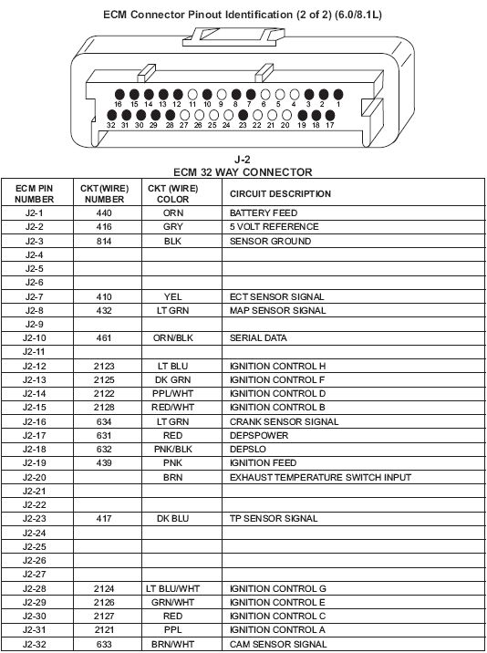
Here are the pinouts for the MEFI-4 ECM used in 6.0 and 8.1L engines:
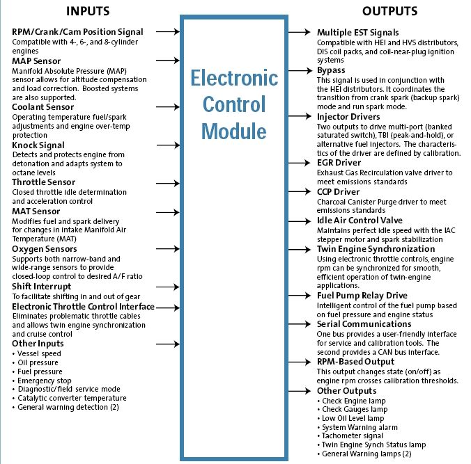
MEFI-4 Inputs & OutputsThe fourth-generation of GM Powertrain's Marine ECM has several important capabilities and features, including:
The following diagram is a representation of the general inputs and outputs of the MEFI-4 system.
Here's a basic look at how the sensors in the speed-density MEFI-4 fuel injection work. Engine load is primarily determined by sensing the current engine speed and reading the manifold pressure via the manifold absolute pressure (MAP) sensor (this is similar to old-fashioned vacuum signal). The MEFI module uses RPM and MAP to select data from a table with rows and columns of numbers that represent injector pulse width values (milliseconds of on-time). When the ECM needs to know how much fuel to deliver it reads the MAP and RPM, then it refers to the corresponding row and column in its fuel table to obtain the correct injector pulse width, also known as the “base pulse width”. Once this pulse width value is obtained there are adjustments made to it based upon other engine operating conditions, however MAP and RPM are the main factors involved in selecting the base value. The engine’s spark advance is also selected in similar fashion. Again, there is a table in the ECM ’s memory with rows and columns of numbers that specify degrees of advance. The desired advance value is chosen based upon RPM and MAP. Once the desired spark advance is obtained, other operating conditions are evaluated and used to adjust the value. The conditions my Turn Key LS2's MEFI-4 system uses to adjust base pulse width and base timing include throttle position, coolant temperature, manifold air temperature, air/fuel ratio (exhaust O2), and knock detection. The complete list of Turn Key LS2 sensors and what they sense and report is as follows: MEFI-4 InputsCS - Crank Sensor (a.k.a. Crank Trigger) – crank angle (i.e. where each cylinder is in its 4-stroke cycle) & RPM. All of these sensors play a vital role in engine operation and are used by the MEFI-4 ECM to sense a variety of operating conditions. The outputs from the MEFI-4 ECM are: MEFI-4 Outputs:EST Signal (Electronic Spark Timing) - to fire the coils / spark plugs. Injector Driver - to fire fuel injectors. IAC Stepper Motor Control - Maintains perfect idle speed with the IAC stepper motor. Fuel Pump Relay - Intelligent control of the fuel pump based on fuel pressure and engine status e.g. shut down fuel pump and therefore engine on overtemp, low oil pressure, engine overspeed, etc. Check Engine Lamp - ECM turns on warning lamp when it detects a problem condition. It also stores a "diagnostic trouble code" or DTC which can be read by a scanner. Tachometer Signal - to drive the tachometer. |
|||||
DTC's, the MIL, and the DLCThe MEFI-4 ECM, like all modern ECM's, continuously monitors sensor inputs and conducts self-diagnostic checks. If any malfunctions are discovered, they are stored in memory as Diagnostic Trouble Codes (DTC's). A DTC is a two-digit code ranging from 12 to 81. When a DTC is stored, the Malfunction Indicator Lamp (MIL) is illuminated. The MIL is the marine term for the "check engine light" (CEL), or "Service engine soon" (SES) light. It is normally a dash-mounted warning indicator lamp. If your installation doesn't have a MIL, don't worry, I'll show you how to add one in a moment. When the MIL lights, the user can retrieve the DTC(s) from the ECM via the Data Link Connector (DLC). The DLC is a 10-pin connector wired into the engine wiring harness. DTC's can be retrieved in one of several ways; either by:
|
|||||
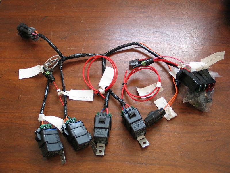 |
The DLC is part of the engine wiring harness. It can be seen here in the top-left of the pic. |
||||
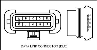 |
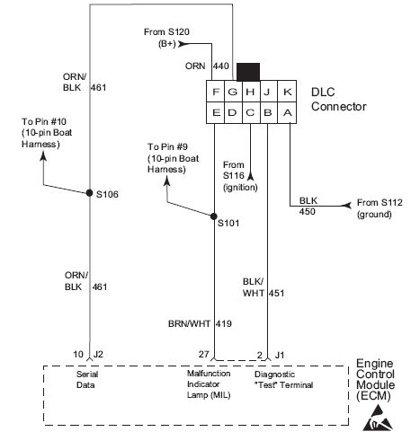
The DLC is a 10-pin connector with pins labelled A through F. (the letter "I" is not used). Only pins A,B,C,E,F, & G are used, as follows: |
||||
| A - Ground Here is the wiring diagram:
Whether or not you have a MIL, the following three methods can be used to retrieve DTC's from the ECM via the DLC if you suspect a problem or malfunction. In order of decreasing cost: | |||||
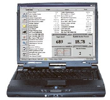 |
Rinda Technologies (www.rinda.com) sells a software program called "Diacom Marine" that runs on a standard PC laptop, along with the required cables to connect the laptop to the DLC. This is the most powerful and flexible of MEFI diagnostic tools, but it is also the most expensive, ranging in cost from about $580.00 - $700.00. According to the company:
This is probably way overkill for the average user, and certainly too much if all you want to do is read the DTC's (which i will shortly describe how to do for less than $5.00!) |
||||
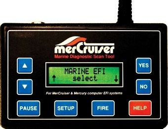 |
The next option down is to use a handheld scanner designed to work with the MEFI system. Unfortunately, OBD I and II scanners do not work, so you have to use a specialized marine scanner, like the MerCruiser or TechMate, again by Rinda Technologies. These units are also pricey at about $400.00, and are designed for the professional marine technician as they will scan all different types of marine EFI systems, not just the GM MEFI. It does have a cool fuel injector tester mode though, as can be seen from the manufacturer's description below:
|
||||
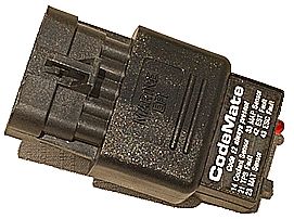 |
The third option, and most reasonably priced of the commercially available tools is the hand-held code flasher, like this Codemate unit from Rinda. This is a neat tool and reasonably priced at about $40.00, but it is pretty limited in its functionality as it is cable only of flashing DTC's on its built-in LED indicator lamp, clearing codes, and setting the ECM in "service mode" so that the base timing can be set. In reality, it is nothing more than a switch and a red LED housed in a fancy plastic housing that plugs directly into the DLC. It is simple and functional though, easy to use, and works well for what it is intended to do. Also, if you don't have a MIL, you could actually install one of these and leave it permanently attached to the DLC and use its built-in red LED as a MIL
|
||||
However, for the truly frugal, you can do everything the Codemate does with nothing more than a paperclip and your MIL (if you have one) or a small LED. But before we get to that, let's look at how the Codemate works and how to hook up your own MIL if you don't already have one. Codemate OperationTo connect the Codemate:
To use the Codemate as a MIL:
In this mode, the Codemate will act just as a dash-mounted MIL does, in that:
To read stored DTC's using the Codemate:
To clear all codes using the Codemate:
Setting Base Timing with the Codemate:
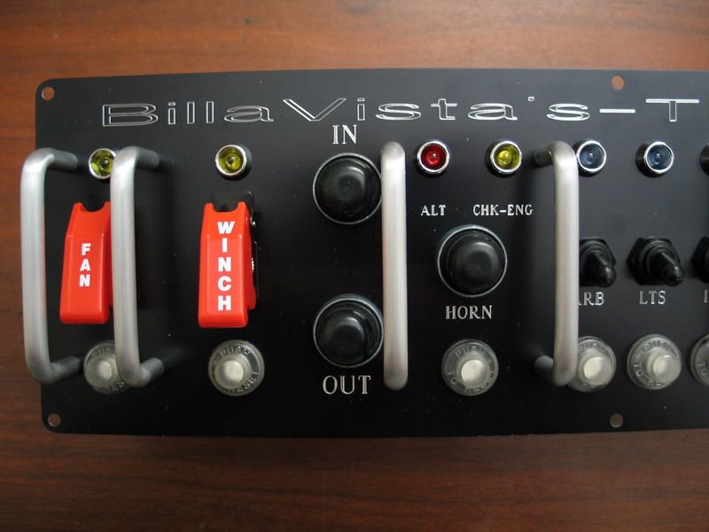
How the Codemate WorksIt's a switch and a LED. When you plug it in, and turn the switch ON, it connects terminals A & B, effectively grounding pin J1-2 of the ECM (the diagnostic link pin), putting the ECM in "service mode". The (+) side of the LED is connected to terminal F, from which it receives 12V+ from the battery. The (-) side of the LED is grounded to terminal E, which the ECM switches on and off to flash the LED and MIL (if present). Making your own MIL.If your MEFI-4 controlled engine doesn't have a MIL, it is very easy to make one. Once you have a MIL, it is very easy to emulate the performance of the Codemate using only a paperclip (or a small switch if you want to be fancy). |
|||||
 |
|
||||
 |
|
||||
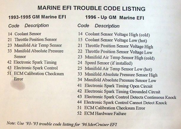
Reading DTC's using your MIL.To have the ECM flash any DTC's on your dash-mounted MIL, follow the procedures above for the Codemate, but simply use a paperclip to jump DLC terminals A & B in place of turning the Codemate switch ON; and remove the paperclip when the procedure calls for the Codemate switch to be OFF. If you want to get a little fancier, you could rig up a switch to connect terminals A & B when you want to put the ECM in service mode. Reading DTC's if you have no MIL.Even if you have no MIL, you can use the DLC to read codes by temporarily connecting an appropriate light between terminals E & F. You will need a 12V resistor-type LED, or a test-light rated safe for use on computer circuit boards. If you are using a LED, connect the (+) of the LED to terminal F, and the negative side to terminal E. Unlike old-fashioned light bulbs, LED's have a positive and negative side. If you get it backwards, you won't damage anything, but it won't work (see wiring diagram above). If you are using a test-light, make sure it is rated for use on computer circuits, otherwise you can damage the ECM. Connect the alligator clip of the test light to a 12V+ source, and use the tip to probe terminal E. Again, the ECM will flash the light by opening and closing the ground to terminal E of the DLC. Just as with the Codemate, using your paperclip and MIL/LED/Test-Light, you can clear any stored codes and set base timing, using the same procedures as for the Codemate. MEFI-4 Trouble CodesNo matter which of the above methods you use to retrieve the DTC's, once you have them, you need to decode their meaning to help with diagnosis and repair of the underlying fault. The following are tables of the MEFI-4 DTC's. each of the three tables presents the same data, although some are more detailed than others because of their different sources: DTC Listing for MEFI-1 through MEFI-4, from the Rinda Technologies Codemate Manual.
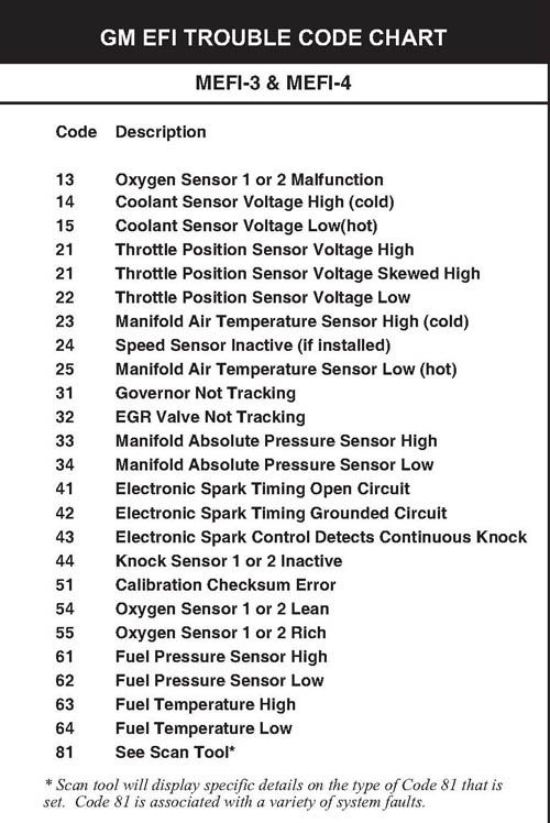
MEFI-3 & MEFI-4 DTC's from the Rinda Technologies MerCruiser Scan Tool Manual.
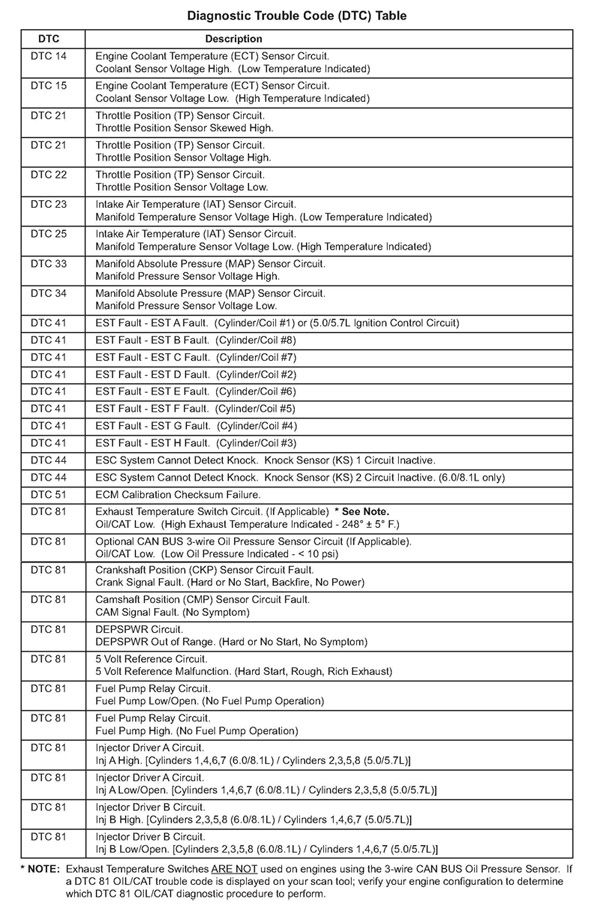
MEFI-4 DTC's from the PCM Marine Engines' MEFI-4/4b Diagnostic Manual
MEFI-4 Diagnostic ManualOnce you have the codes, and have decoded them, it can be very useful to have a good quality diagnostics manual to help with diagnoses and repair. PCM Marine Engines have an excellent manual, which includes full diagnostic procedures, wiring diagrams, sensor operation data, and more. It's a must-read for any MEFI-4 owner / operator. Download by clicking the pic or name below: |
|||||
 |
MEFI-4 Diagnostic Manual. | ||||
MEFI-4 Sensor Locations in my Turn Key LS2.The following series of pictures and text illustrate the location of the Turn Key LS2's MEFI-4 speed-density sensors and their primary uses. |
|||||
.jpg) |
1 = CPS – camshaft position sensor. The CPS tracks and reports the rotational position of camshaft and therefore valve/stroke timing. It is also used to detect misfires. The cam sensor is located on the front engine cover, as shown. |
||||
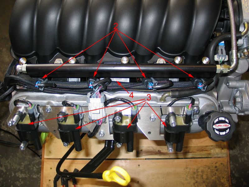 |
2 = Fuel injectors. 3 = Ignition coils. 4 = Firing order placard ( 1-8-7-2-6-5-4-3 )
|
||||
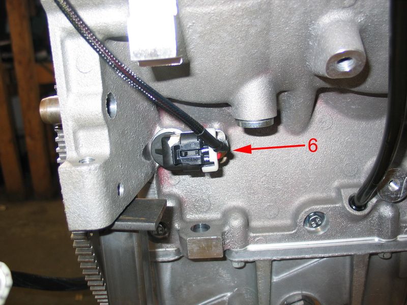 |
6 = Crank Sensor (CS). The CS reads the 58x crankshaft position encoder attached to the rear of the crank and thereby tracks and reports the crank angle (location) & engine RPM. Engine RPM, or engine speed, is one of the main factors used to determine injector pulse width and ignition timing in a speed-density system. |
||||
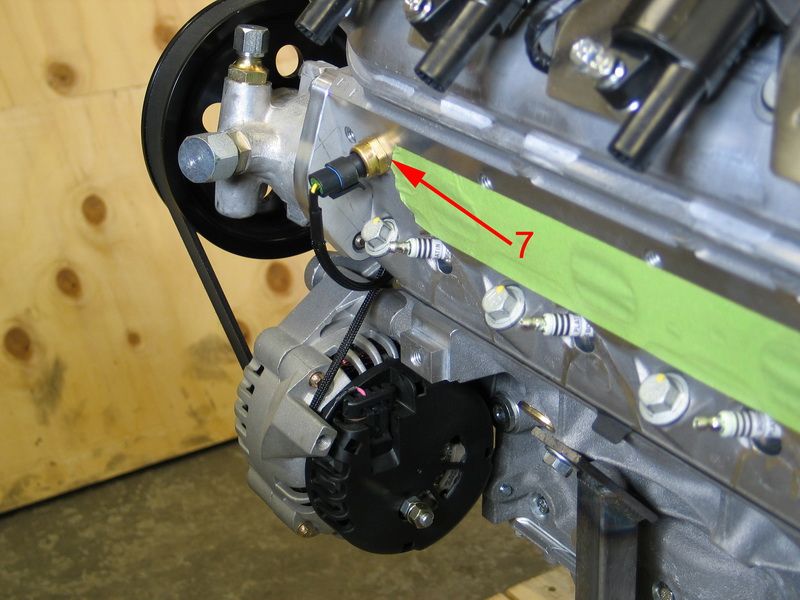 |
7 = Coolant Temperature Sensor (CTS). The CTS monitors engine temperature which is used in a wide range of functions, from telling the ECM when to use cold start-up enrichment mode to turning on the electric radiator cooling fans to fuel/spark adjustments and engine over-temp protection. Cold engines require more fuel to operate so the ECM uses the CTS information to enrich the air/fuel mixture in much the same way an automatic choke did on carbureted engines. Depending upon how cold the engine is, the ECM will increase the base pulse width values obtained from it’s main fuel table and then gradually taper off the increase as the engine warms up. The CTS is also used for several other temperature-dependent functions including: the modification of idle speed, IAC motor position, and spark advance as well as detecting engine overheat situations. |
||||
.jpg) |
8 = Knock Sensor (KS). The KS detects engine knock or ping. When it detects this high-frequency vibration/sound this information is used to retard timing and prevent pre-ignition. This system protects the engine from damage caused by detonation or pre-ignition while allowing the most aggressive ignition timing advance possible. It can also serve to adapt the system to varying octane levels in different fuels, although premium (91+ octane) unleaded gasoline is recommended. When the knock sensor detects detonation (or "knock") it signals the ECM to retard timing (called "knock retard"). The ECM then retards timing until detonation stops and, once it stops, advances the timing again. The loop takes only milliseconds and is continually occurring such that spark timing is always at the optimum level for best performance, highest fuel economy, lowest emissions and the octane of the gasoline being used. |
||||
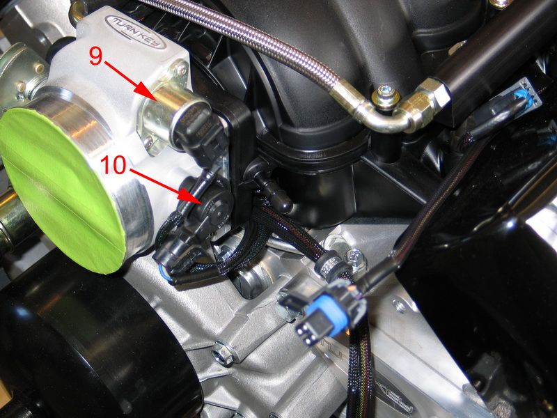 |
9 = IAC – Idle Air Control Valve. The IAC supplies metered air at idle, and the built-in sensor reports the solenoid plunger position to the ECM. The IAC is used to add more air to the engine as it is decelerating or warming up, like a high idle cam on a carb linkage, in order to keep the engine from stalling.\ In this manner the IAC is used by ECM to control idle RPM. To increase RPM, the ECM commands the plunger to extend, allowing more air to bypass the throttle blade. To decrease idle RPM the ECM commands the plunger to retract, reducing or preventing air from bypassing the throttle blade. |
||||
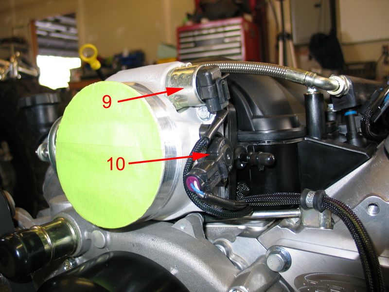 |
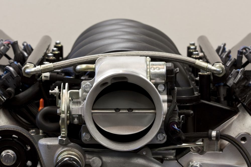
10 = TPS – Throttle Position Sensor The TPS reports the throttle blade position (or level of opening), and more importantly, its rate of change of position - i.e. is it opening, and how fast (an indication of acceleration) or is it closing, and how fast (an indication of deceleration). By monitoring the precise position of the throttle blade via the TPS, the ECM can respond quickly to driver-commanded throttle changes. |
||||
| The throttle position sensor is probably the most misunderstood of all engine sensors. While readings from this sensor are important in determining idle and wide open throttle conditions (eliminating the need for mechanical switches), its main purpose is to provide information related to engine acceleration and deceleration. Under normal running conditions, above idle and less than full throttle, the MEFI-4 ECM uses "spreading" to sense if the operator is trying to rapidly accelerate or decelerate. It does this by determining how much the TPS voltage has changed since the last time the value was read. The sensor’s absolute position and corresponding voltage are less important than the amount it has changed. The MEFI-4 ECM reads the TPS voltage every few milliseconds and calculates the difference between the current and last readings. If a large enough change is detected, adjustments are then made to the fuel injector’s base pulse width value to provide extra fuel for rapid acceleration or decrease in fuel for deceleration. Again, the exact TPS voltage is important at idle or wide open throttle; however during normal running conditions it’s the change and rate of change in TPS voltage that matters most. | |||||
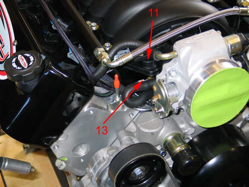 |
11 = MAP – Manifold Air Pressure Sensor The MAP measures the pressure of the air in the intake manifold as a measure of how much air is being drawn into the engine. The lower the pressure (higher the vacuum), the more air that is being drawn into the engine, and therefore the more power the engine is making and the more fuel it needs. This information is one of the key factors in the speed-density ECM's fueling calculations as it accurately represents the load on the engine. The MAP sensor allows for load correction and altitude compensation. |
||||
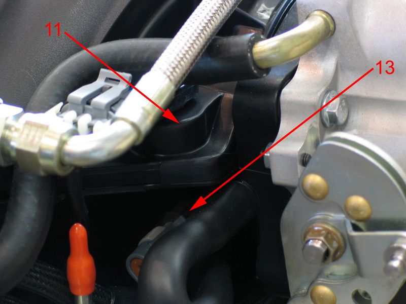 |
13 = IAT – Inlet Air Temperature Sensor The IAT reports the temperature of the air entering the intake manifold (and therefore also the air's density). Inlet air temperature data is important in calculating the proper fueling to achieve optimum air/fuel ratio for the best performance and efficiency for the given conditions. The ECM uses the IAT data to alter fueling and timing curves which results in modifying fuel and spark delivery for changes in intake manifold air temperature. |
||||
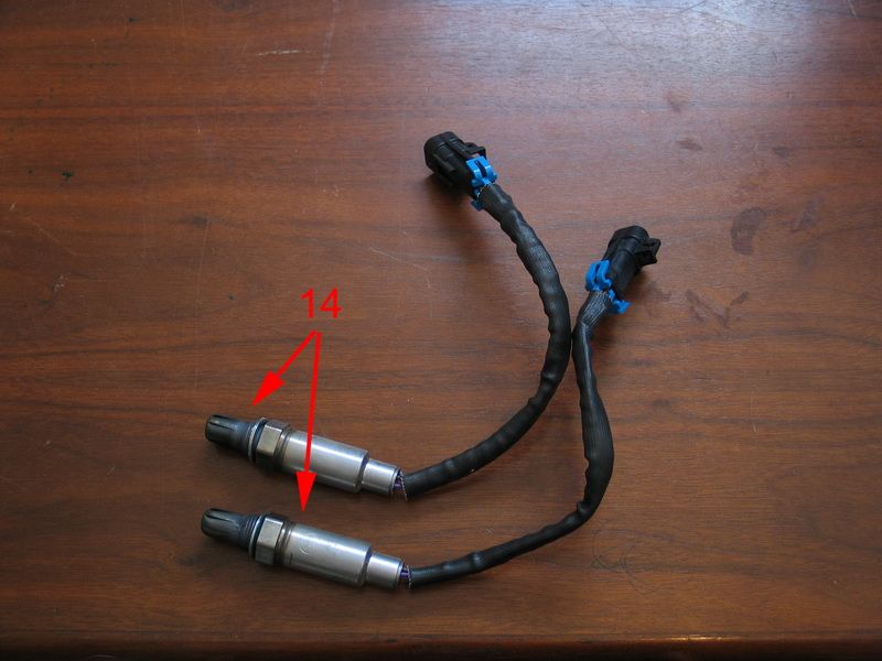 |
14 = O2 - Oxygen Sensors. When installed, the O2 sensors are located in the exhaust collectors, just after the headers. O2 sensors monitor O2 level in exhaust which the ECM uses to determine how rich or lean the air/fuel mixture is and make necessary adjustments. The O2 sensors provide a feedback loop (called closed-loop operation) for the ECM to control to the desired air/fuel ratio. The O2 sensors are the EFI systems "report cards" - they tell the ECM "how am I doing" with regards to air/fuel ratio when in closed-loop mode. |
||||
Other Reference Data:
|
|||||

|
Sources: Turn Key Engine Supply
|


|