 |
Fastener Tech – The Nuts and Bolts of It By Bill "BillaVista" Ansell |
IntroductionWhy an Article on a Topic as “Simple” as Nuts and Bolts? Because an understanding of fastener tech forms a solid foundation for all extreme off-road tech. It’s a great place to start – from the ground up. Much of what we do as builders and maintainers of off-road vehicles is strictly custom, often one-off, stuff. We don’t have the luxury of detailed instructions or the benefit of a major manufacturer’s years of engineering and research. In short, we’re on our own so we need to have a good solid understanding of fastener tech in order to answer questions such as: What size and type of thread should we use to attach our custom suspension links? What type of locking mechanism should we use on our beadlock wheels? Should we use studs or bolts to attach our steering arms to the knuckles? |
 |
BoltsThe basic parts of a bolt are:
|
|
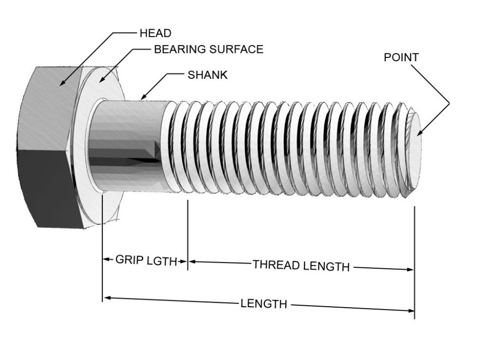 |
Figure 1 – The basic parts of a bolt. | ||||||||||||||||||||||||||||||||||||||||||||||||||||||||||||||||||||||||||||||||||||||||||||||||||||||||||||||||||||||||||||||||||||||||||||||||||||||||||||||||||||||||||||||||||||
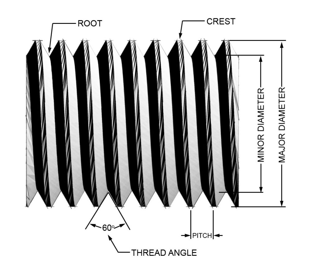 |
Figure 2 – The parts and dimensions of a thread. | ||||||||||||||||||||||||||||||||||||||||||||||||||||||||||||||||||||||||||||||||||||||||||||||||||||||||||||||||||||||||||||||||||||||||||||||||||||||||||||||||||||||||||||||||||||
The basic parts and most important dimensions of a thread are illustrated in Figure 2. A male thread is depicted, but the terms apply equally to female threads. The thread pitch is the distance from a point on the thread to a corresponding point on the next thread measured parallel to the bolt’s axis (equal to 1 divided by the # of threads per inch). The major diameter is the largest diameter of a thread (measured over the crests of the thread) while the minor diameter is the smallest diameter of a thread (measured over the roots of the thread). NutsCompared to a bolt, a nut is a fairly simple beast. It is really nothing more than a chunk of steel into which is cut appropriate internal threads so that it may be screwed onto a bolt. The flat area of the nut that contacts the joint when it is tightened is known as the “nut face”. Because the only practical way to form the internal threads is to cut them into the nut, these threads are always weaker than the rolled threads of a quality bolt or stud. Selection of an appropriate nut consists of choosing the correct grade and thread to match the bolt used. The only other concern is whether or not to use some sort of “locking” nut. Unless an assembly sees very little load and must also be frequently disassembled, it is best to always use some sort of locking nut – selection of which is covered later in this article. Bolt, Screw, or Stud? The choice between bolt or screw is really just a naming convention. A bolt is an externally threaded fastener intended to be used with a nut. It is tightened or loosened by turning a nut on the bolt’s threads. A screw is an externally threaded fastener designed to be threaded into a tapped hole in a part. A screw is tightened or loosened by turning it by the head. In practice, most people call both bolts and screws, “bolts” – in the majority of this article the terms can be used interchangeably. A stud is an externally threaded fastener that has 2 threaded ends with a non-threaded shank between them. It is designed to have one end threaded into a tapped hole while the other end uses a nut. Most often one end is coarse thread, for threading into a tapped hole, and the other end that takes the nut is fine thread, so that the benefits of both fine and coarse threads can be utilized – these differences will be discussed later. In the manner of operation, a stud is no different than bolt, they are both clamping devices, and neither should really be used as locating dowels or bearing trunnions. The advantage to using a stud occurs when you have a piece that needs to be fastened to a large, cast part that requires semi-frequent disassembly. By using a stud, the assembly can be disassembled leaving the stud in place, reducing the chance of fouling or stripping the internal threads in the cast part, which would be difficult to repair. Using studs to hold a steel steering arm to a cast or forged steering knuckle is an excellent example of this principle. |
|||||||||||||||||||||||||||||||||||||||||||||||||||||||||||||||||||||||||||||||||||||||||||||||||||||||||||||||||||||||||||||||||||||||||||||||||||||||||||||||||||||||||||||||||||||
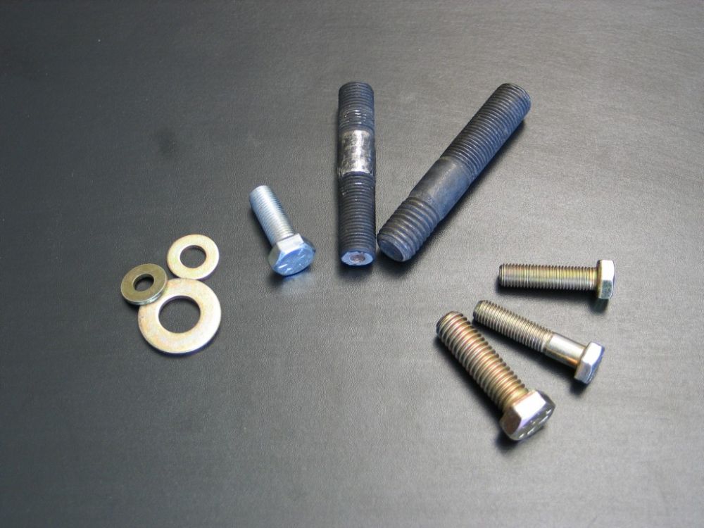 |
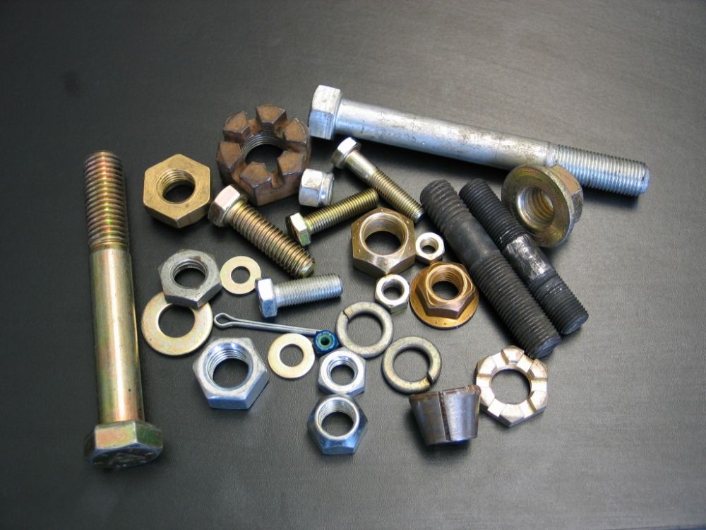
Figure 3 - Clockwise from left: Grade 8 flat washers, Grade 5 UNF bolt, UNF/UNF stud, UNC/UNF stud, Grade 8 bolts. | ||||||||||||||||||||||||||||||||||||||||||||||||||||||||||||||||||||||||||||||||||||||||||||||||||||||||||||||||||||||||||||||||||||||||||||||||||||||||||||||||||||||||||||||||||||
The Unavoidable PhysicsIn discussing fastener selection and joint design we must make use of a few engineering terms. Stress is a force or load applied to a part, divided by how big the part is, in other words force per unit of cross sectional area, commonly measured as pounds per square inch (PSI). Strain is a change in shape or dimension in response to a stress. The concept of strain allows us to describe how a part or material responds to an applied force or load. There are 3 things that can happen when a bolt strains:
How Bolted Joints WorkNuts and bolts are clamps. They work by tightly clamping the parts of a bolted joint together. They are able to do this because of stress and strain. When a nut and bolt is tightened in a joint, the bearing surface of the bolt and the nut face come up against the halves of the joint. If tightening continues, the bolt will stretch slightly – it will strain. As long as it is not stressed beyond its yield point it will try and return to its original length, establishing a clamping force. This bolt-stretch, which creates the desired clamping force, is called bolt pre-load. Establishing and maintaining appropriate fastener pre-load in a bolted joint is the principle on which all bolted joints work and is the chief determining factor in how strong, tight, and fatigue-resistant a bolted joint will be. Most, if not all, properly designed bolted joints in a 4x4 application will cause the joint and the bolt to be stressed in one of two distinct ways: tension or shear. |
|||||||||||||||||||||||||||||||||||||||||||||||||||||||||||||||||||||||||||||||||||||||||||||||||||||||||||||||||||||||||||||||||||||||||||||||||||||||||||||||||||||||||||||||||||||
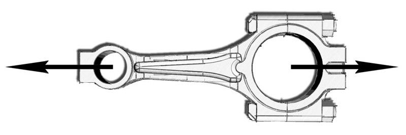 |
Figure 4 – Connecting rod is an example of a bolted tension joint. | ||||||||||||||||||||||||||||||||||||||||||||||||||||||||||||||||||||||||||||||||||||||||||||||||||||||||||||||||||||||||||||||||||||||||||||||||||||||||||||||||||||||||||||||||||||
Tension JointsA joint can be designed so that the bolt will be loaded in tension (Figure 4).The parts are loaded such that they to try and pull apart. In this case the load is applied along the longitudinal axis of the bolt. A connecting rod bolt is an example of a bolt loaded in tension. Shear JointsA joint can be designed so that it will be loaded in shear. In this case, the load on the joint acts perpendicular to the length of the bolt, and tries to cut, or shear, the bolt in half. Bolts used to hold suspension links in their brackets are loaded in shear. There are two sub-types of shear joint: bearing and friction. Bearing Shear JointsIn a bearing joint, it is the very close fit of the fastener in the holes that carries the load. Assembled properly, the bolt will be an extremely close fit in its hole – such that SAE fasteners and drilled holes are not appropriate – they allow too much tolerance or slop. Bearing shear joints should be avoided if possible, unless specialized aerospace bolts with exacting tolerances and precise hole-making methods (machining or reaming) are employed. The exception to this rule is if some additional method is employed to ensure there is an extremely tight fit between the fasteners and the holes. The most common method is to employ a floating, split, conical-shaped washer on the fastener with a matching tapered hole in the part. In this fashion, as the fastener is tightened, the conical washer cinches down in the tapered hole as well as against the shank of the bolt or stud, creating a tight, zero clearance fit and preventing slop, wear, and fatigue. The Dana 44 front axle steering arm attachment is a classic example of this method. Zero-clearance locating dowels are another method that can be employed. Friction Shear JointsThe second type of shear joint is a friction shear joint. In this case, the bolt clamps the parts of the joint together so that the friction between the clamped parts carries the majority of the load. When this is the case, the bolt itself is loaded only in tension, as it is designed to be, at least until the load overcomes the friction and the parts slip, loading the bolt in shear. Obviously the in-service load on the joint determines the amount of friction required, which in turn determines the clamping force required, and therefore the correct bolt pre-load, as measured by torquing the bolt to spec. When shear joints are employed, whether they are friction or bearing, they should always be designed so that the fastener is loaded in “double shear” if possible. As can be seen in Figure 5, the fastener or bracket must fail in 2 places for the joint to fail, making it almost twice as strong as the single-shear joint seen in Figure 6. |
|||||||||||||||||||||||||||||||||||||||||||||||||||||||||||||||||||||||||||||||||||||||||||||||||||||||||||||||||||||||||||||||||||||||||||||||||||||||||||||||||||||||||||||||||||||
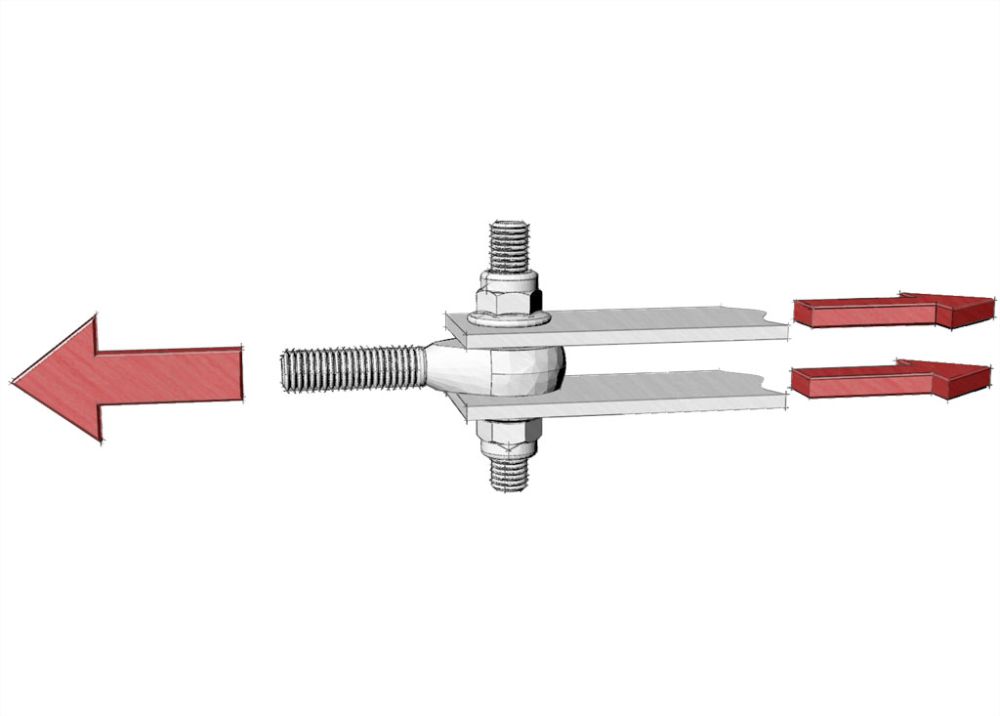 |
Figure 5 – Double shear joint. | ||||||||||||||||||||||||||||||||||||||||||||||||||||||||||||||||||||||||||||||||||||||||||||||||||||||||||||||||||||||||||||||||||||||||||||||||||||||||||||||||||||||||||||||||||||
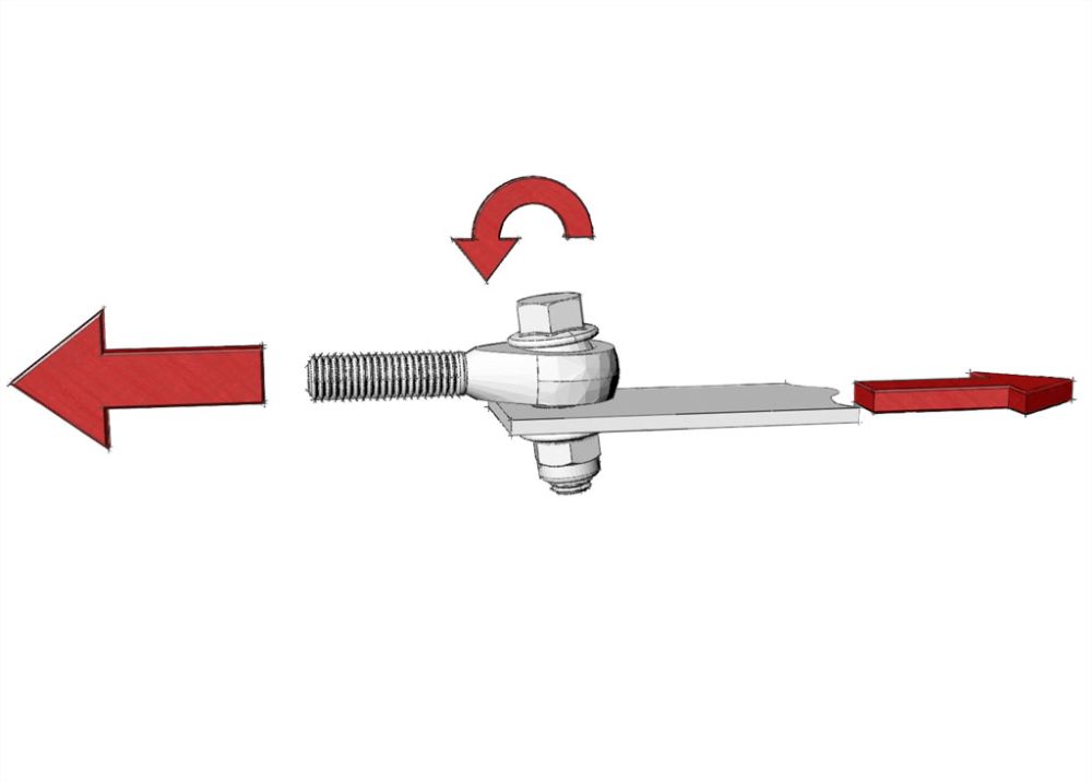 |
Figure 6 – Single shear joint. Note the bending load on the fastener. | ||||||||||||||||||||||||||||||||||||||||||||||||||||||||||||||||||||||||||||||||||||||||||||||||||||||||||||||||||||||||||||||||||||||||||||||||||||||||||||||||||||||||||||||||||||
Because shear joints (which are the most demanding on fasteners) are very common and are often highly loaded, as in suspension bracketry, the following rules of thumb can help achieve successful joint design:
There is a third type of load all too often imposed on bolts in 4x4 joints, that should be avoided at all costs. This type of load is called bending load and, naturally, occurs when the forces try to bend the bolt. Bending load is actually a combination of tension and compression load on opposite sides of the bolt. Bolts are not designed for this type of load, and if subjected to it will quickly fatigue and fail. In a bending load, the force is acting perpendicular, or nearly perpendicular, to the bolt, similar to a shear load. The difference is, in a shear joint, the parts of the joint themselves are clamped very closely together, creating friction and supporting the bolt. In a bending load, the force is applied some distance from the support of the joint. As a rule of thumb, bending loads are assumed when the load is applied at a distance from the joint greater than the diameter of the bolt. In the case of the single shear joint in Figure 6, the bending load is caused by a lack of support from the overly-thin joint. It is common to observe bending loads in steering linkages where excessively long spacers have been used between the brackets and the spherical rod ends. Fastener SpecificationsOnce the joint is designed, the next step is to select the right fastener. There are an almost limitless number of options available to the 4x4 builder. Time and space restrictions prevent a complete discussion of all possible types here (see ‘resources’ section for further reading). For the sake of simplicity and brevity, we shall concentrate on steel SAE fasteners. Table 1 provides the specifications and method of identification of the fasteners of greatest interest to us. Table 1 - SAE AND ISO Grdae Markings and Mechanical Properties for Steel Fasteners
What Size?The diameter of the fastener used will often be pre-determined by the joint design, as in the size of the collar in a bushing. If not, the diameter will have to be determined by a careful analysis of the clamping force and/or shear strength required. Tables 1 and 2 can be used for guidance with the knowledge that an SAE fastener’s shear strength is approximately 60% of its tensile strength. The length of the fastener should be carefully chosen so that there is sufficient grip length to hold the joint securely at the required torque setting without bottoming the nut between the shank and threads and without using washers as shims; while simultaneously having sufficient thread engagement in the nut or tapped hole, without excessive threads protruding from the nut. As a rule of thumb a bolt should protrude through a nut by at least 3 full threads. The reason for this is because often the first 2 or 3 threads of a bolt are poorly formed, usually due to a chamfer on the end of the bolt for easier starting. Thus they will not produce the full strength of the fastener. A screw should thread into a tapped hole at least 1.5 times the diameter of the screw, to ensure the screw will break before stripping the internally tapped threads. Formulae for more precise calculations are published in the Machinery’s Handbook. Table 2 –Torque Specs for SAE Coarse and Fine Thread Fasteners
* The upper end of these values represents approximately 85-90% of the fastener’s maximum torque. What Grade?This is a simple question, despite persistent myths to the contrary. The answer is, SAE Grade 8 from a reputable national manufacturer. Un-graded and Grade 2 fasteners have no place whatsoever on a 4x4 as they are weak and unreliable, and while Grade 5 fasteners may exhibit the necessary strength in some applications, in others they do not, and the lower strength and possible misuse of them is simply not offset by the marginal cost benefit. Grade 8 bolts exhibit greater tensile, yield, and shear strength as well as greater fatigue resistance and, just as important, are capable of greater torque specs and therefore much greater pre-load and clamping strength. There exists an often quoted myth, that Grade 5 bolts are better in shear than Grade 8 since they will bend before breaking. Not true. Shear strength of alloy steel is approximately 60% of its ultimate tensile strength. Reference to Table 1 shows that the yield strength of a Grade 8 bolt is higher than the ultimate strength of a Grade 5 bolt. The Grade 5 bolt will therefore always fail first whether in tension or shear. The only “gotcha” with the Grade 8 bolt is that, being harder, it is more “notch sensitive.” This means it is more sensitive to build up of stress concentrations caused by notches, nicks, and gouges leading to fatigue and failure. This becomes a non issue if good quality new fasteners are always used and periodically inspected. Different grades of fasteners can be identified by the markings on their heads (Table 1). Of course, matching grades of nut and bolt/stud must be used together. Note that many manufacturers (e.g. Caterpillar, Bowman) manufacture bolts to specifications that exceed those for SAE Grade 8 bolts. These fasteners (Figure 7) are often marked in a similar fashion to SAE graded hardware by means of dashes embossed on the head of the bolt. Despite this, it is not technically correct to refer to these bolts as “Grade 12” or such, as no such SAE specification exists. Bowman calls their line “Bowman Special Alloy.” |
|||||||||||||||||||||||||||||||||||||||||||||||||||||||||||||||||||||||||||||||||||||||||||||||||||||||||||||||||||||||||||||||||||||||||||||||||||||||||||||||||||||||||||||||||||||
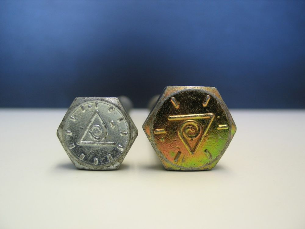 |
Figure 7 - Bowman Grade 8 bolt & Bowman “Special Alloy” bolt. | ||||||||||||||||||||||||||||||||||||||||||||||||||||||||||||||||||||||||||||||||||||||||||||||||||||||||||||||||||||||||||||||||||||||||||||||||||||||||||||||||||||||||||||||||||||
Which Thread – Coarse or Fine?While there exist many different classes of threads, the only classes likely to be of interest to us are Class 2A/2B and Class 3A/3B (the ‘A’ denotes external threads; the B denotes internal threads). Class 2A/2B is the recognized standard for normal production of the great bulk of commercial bolts, nuts and screws. Class 3A/3B is used where a close fit between mating parts for high quality work is required. This class is usually only found on certain specialized engine hardware (e.g. connecting rod bolts) or aerospace fasteners. The vast majority of our fasteners will be in Class 2A/2B. The thread class should be matched between nut and bolt. When tapping a hole, be sure the tap cuts the same class of thread as the screw or stud you intend to use. SAE fasteners come in a choice of either Unified National Coarse (UNC) or Unified National Fine (UNF). Sometimes the older designations NC and NF are still used. The differences are as follows:
Why Torque?The reason we torque fasteners to a given spec is because it is the most convenient, practical method for controlling the amount of pre-load or “stretch” in the bolt, which in turn provides the necessary clamping force for the assembly. Torque values are calculated considering the material of the nut and bolt, the surface finish (including lubricants or retention compounds), and other factors. In practice, the most common method is to use a table of pre-calculated torque values such as that shown in Table 2. There is a pitfall to controlling pre-load by torque though. The majority of the torque used to tighten a fastener is not directly used in achieving the desired pre-load. Of the torque we apply to a fastener, approximately 45% is consumed to overcome friction in the threads, 40% consumed to overcome friction between the nut face and the joint, and another 5% is consumed by prevailing torque - the torque required to screw a locking-type nut down the threads of a bolt. Thus only 10% is available to produce bolt pre-load. This means that changes in either the friction of the threads (as in rusty or oily threads), or under the nut face (when flat washers are used or the nut embeds in the bracket) can have a huge impact on the pre-load. This is why top pro engine builders tend to use strain gauges or ultrasonic measurement to measure actual bolt stretch, rather than torque. These methods are not practical for most of us though, but there are some rules we can follow to minimize the pitfalls:
The more a nut and bolt is tightened, the greater the pre-load in the bolt, and therefore the more external load it can sustain within material limits. As the bolt strains to return to its original length it “fights back” against any external tension load, until its pre-load clamping force is exceeded. In addition, the tighter the bolt and nut, the more friction in the threads, and the less it is susceptible to loosening. In summary – loose is useless and tight is right! But how tight is tight enough? A good rule of thumb is to use an established table of recommended torque values or to tighten a fastener to about 70-80% of its maximum torque capacity. Note that almost all torque specifications published are for clean, dry threads. In calculating assembly torque for any threads that are not clean and dry, exact figures are difficult to determine – experience and judgement are the best tools, along with direct strain measurement in critical applications. Common compounds applied to threads such as grease and anti-seize normally reduce the required torque by 20-40% or more. It’s worth noting the reason critical fasteners such as ring gear bolts are never to be re-used. Such bolts are required to achieve extremely high clamping loads in order to do their job. This means they must be installed and torqued so highly that they approach their yield point, sometimes very closely. Add the stress they see in service, and we cannot be sure that they will retain all of their tensile strength if they have been removed and reinstalled. Setting TorqueThe proper technique for tightening a fastener to spec is as follows: Tighten the fastener a little at a time (3 or more steps), pausing to allow the stress in the threads to relax. Finish with an even pull until the torque wrench clicks or indicates final torque, pause, and then pull again to check. Checking TorqueWhen checking an assembled joint, such as wheel lugs or steering-arm-to-knuckle joints, the best procedure is to loosen the fasteners and torque evenly to spec, as above. When one needs to know if the fastener had loosened in service, one can simply place the socket over the nut, make an alignment mark between the socket and a part of the joint that is stationary, back the nut off a quarter turn, and then re-torque to spec – how close the alignment marks line up will give an indication as to the degree of loosening in service Figure 8). The snag is: this method is problematic for checking fasteners that use chemical thread-locking compounds. Breaking the chemical bond in checking the torque defeats the purpose of the thread locker, and the resulting cured compound in the threads increases thread friction, resulting in less torque available for pre-loading the fastener – meaning the fastener will now be looser and weaker if torqued to the same spec again. However, since the cured thread locker will add to the friction in the threads, it stands to reason that it would take more than the original assembly torque used when it was not cured, to break the fastener free either by tightening or loosening. Therefore, torque can be checked by holding the bolt head stationary, and applying assembly torque to the nut, while checking to make sure there is no relative movement between nut and bolt. If the torque wrench indicates assembly torque and the nut and bolt have not moved relative to one another, the fastener is still tight. |
|||||||||||||||||||||||||||||||||||||||||||||||||||||||||||||||||||||||||||||||||||||||||||||||||||||||||||||||||||||||||||||||||||||||||||||||||||||||||||||||||||||||||||||||||||||
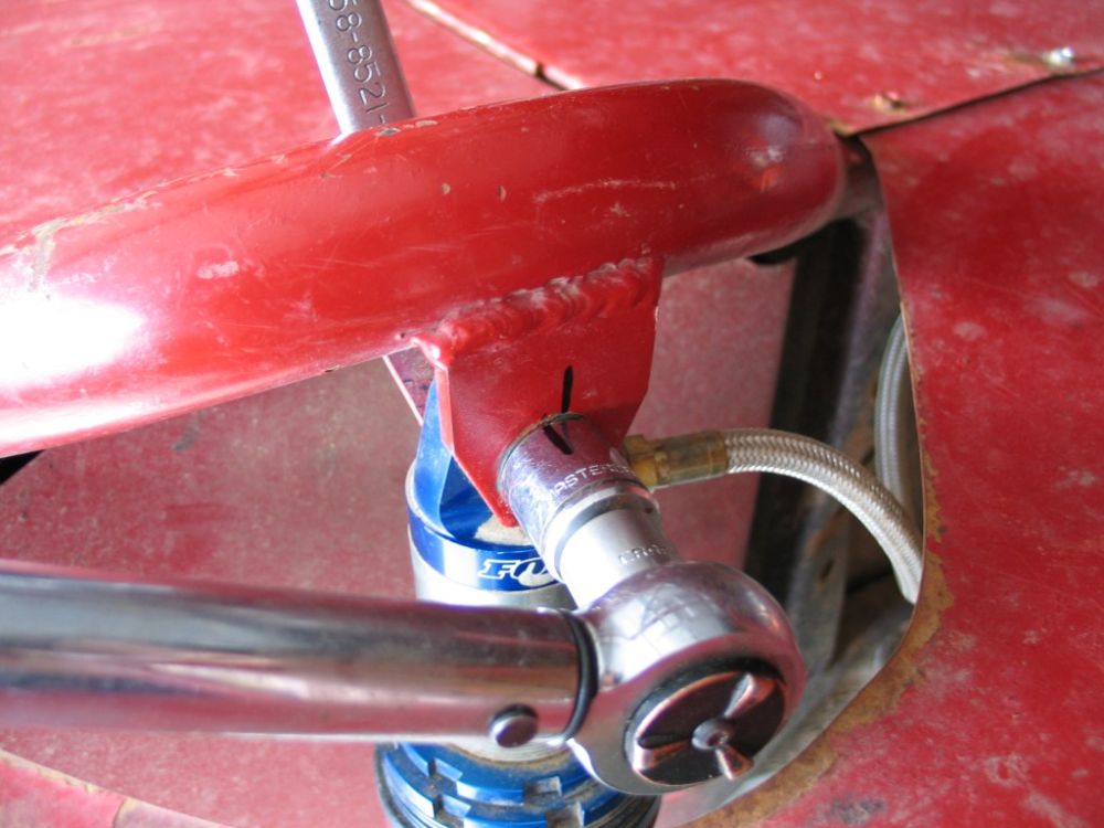 |
Figure 8 – Torque checking. | ||||||||||||||||||||||||||||||||||||||||||||||||||||||||||||||||||||||||||||||||||||||||||||||||||||||||||||||||||||||||||||||||||||||||||||||||||||||||||||||||||||||||||||||||||||
WashersIf a washer is necessary, there is really only one type that should be considered in a structural bolted joint, and that is the flat washer. Its purpose is to act as an increased load-bearing surface for either the head of the bolt and/or the face of the nut. This use should only be considered when using a nut or bolt with insufficient bearing area resulting in it digging into the surface of the joint (embedding) if a washer were not used. Embedding is to be avoided. Not only does it damage the surface, but the unpredictable stress that occurs when fasteners embed into the joint destroys any chance we have of achieving proper pre-load by torquing. The only other purpose a flat washer serves is to act as a shim to either position the threads more favourably, or to adjust the position of a castle nut so that the slots better line up with the hole in the bolt. Use of washers as shims is dubious at best, and should be avoided if possible by using the correct length bolt. Preventing LooseningAs we have seen, loose fasteners are weak and quickly lead to failure. The best way to prevent a fastener from loosening is to do it up tightly enough that there is sufficient clamping force across the joint to prevent relative motion between the bolt head/nut and the joint, as well as sufficient inter-thread friction to prevent any relative motion between the threads. If a fastener is new, clean, dry, torqued to the proper spec with a calibrated wrench and it is properly sized and used in a sufficiently rigid joint - it will stay tight. Of course, there are a lot of “ifs” in that statement, and we off-roaders live in an imperfect world at best, so there are several methods available to assist in preventing the loosening of fasteners. Which is best for the application depends partly on the root cause of the loosening, and partly on the characteristics of the locking device. Root causes of loosening are usually one of:
The following are the most effective methods of helping to control loosening – but none will replace a properly tightened fastener. There are many other methods not listed (such as split beam nuts, star washers, Bellville washers and lock wiring), simply because they are uncommon, largely ineffective or too complex and expensive for the majority of our uses. Lock NutsThere are many types and brands of lock nuts available (Figure 9). There are also countless proprietary types available, but most use some variation, or combination, of the following basics: Nylon Collar Lock NutsThe most common type of locking nut, they have a small nylon insert at the top of the nut, the ID of which is slightly less than the major diameter of the bolt’s thread. As the bolt threads into the nylon area it impresses its own threads into the nylon and the friction bond achieved resists loosening. Nylon collar lock nuts can be re-used up to about 10 times, but are only good up to temperatures of about 250 degrees Fahrenheit. Deformed Thread (Elliptically Offset) Lock NutThis all-metal lock nut is my personal favourite. It has no practical temperature limit and can be reused many, many times. The top threads of this nut are deformed (usually elliptical or triangular in shape) so that they tightly grip the male threads of the bolt, creating a very secure locking action but without damaging the male threads. Examples include Torquenut®, Stover®, and Clevloc® nuts. Castellated NutThe castellated nut has slots cut in the top and is used with a bolt that has a single hole through its threaded end. In use, the nut is installed and torqued to spec and then rotated so that the nearest slot aligns with the hole in the bolt. A cotter pin is then installed through the slots and the hole, to lock the nut in place. The disadvantage to this type is that, because of the clearance required between the slots to allow for cotter pin insertion, it is difficult to achieve a precise torque setting and simultaneously line up the hole and slots. For the same reason, the cotter pin prevents the nut from backing off, but due to the clearances involved, does not hold the nut tightly to prevent any loosening. The castellated nut is best suited for low-torque applications such as holding a wheel bearing in place. |
|||||||||||||||||||||||||||||||||||||||||||||||||||||||||||||||||||||||||||||||||||||||||||||||||||||||||||||||||||||||||||||||||||||||||||||||||||||||||||||||||||||||||||||||||||||
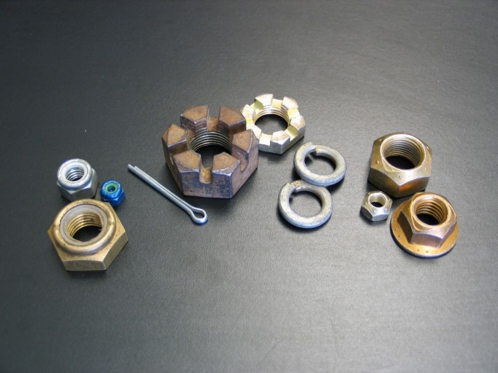 |
Figure 9 – From left: nylon collar lock nuts, castellated nuts, spring lock washers, flanged and non-flanged deformed thread lock nuts. | ||||||||||||||||||||||||||||||||||||||||||||||||||||||||||||||||||||||||||||||||||||||||||||||||||||||||||||||||||||||||||||||||||||||||||||||||||||||||||||||||||||||||||||||||||||
Spring (Split) Lock WashersI mention this so-called locking device only in an effort to turn you off them forever! I can’t stand the things and believe they are next to completely useless. The typical spring washer is made of slightly trapezoidal wire formed into a helix of one coil. It is supposed to work by acting as a compressed spring – presumably to add to bolt pre-load and prevent loosening. However, when we combine our knowledge of bolt stretch and pre-load with the fact that the split washer is always compressed completely flat under any properly tightened bolt, we can see that the idea that this thing would effectively contribute to bolt pre-load is ridiculous. The only other way it could possibly help is that the sharp trapezoidal ends dig in slightly to the bolt’s bearing surface and the face of the joint (but only if the washer were harder than the bolt’s bearing surface, which is extremely unlikely). However, when we remember the pitfalls of inaccurate pre-load caused by excessive/unpredictable friction under the bolt head/nut face consuming too much of the tightening torque, we can see that this is hardly a good idea. Not only that, but experience teaches us that the damn things invariably squish and splay out under any decent amount of torque anyway. I think they are useless junk that should be avoided on extreme off-road machines! Thread Locking CompoundsThe final method to consider is the family of chemical thread locking compounds such as Loctite™. A thread locking compound is an anaerobic adhesive, meaning it is applied to threads in a liquid form, and when the fasteners are joined and oxygen is excluded, they cure into a solid, plastic-like compound “locking” the threads together. They are available in a wide variety of strengths to suit different applications, from those that can be disassembled by hand to those that require the application of heat and power tools. The manufacturer’s application directions should be carefully followed and it is advisable to avoid using too much – usually a drop or two will do. They provide excellent resistance to loosening but can be messy and expensive. They also make tightening to spec, torque checking, and disassembly more complicated. Most thread locking adhesives actually create more friction in the threads than clean, dry threads so that assembly torque will have to be adjusted accordingly. |
|||||||||||||||||||||||||||||||||||||||||||||||||||||||||||||||||||||||||||||||||||||||||||||||||||||||||||||||||||||||||||||||||||||||||||||||||||||||||||||||||||||||||||||||||||||
|
|||||||||||||||||||||||||||||||||||||||||||||||||||||||||||||||||||||||||||||||||||||||||||||||||||||||||||||||||||||||||||||||||||||||||||||||||||||||||||||||||||||||||||||||||||||
|