 |
Chopsaw Notching & Link Construction By Bill "BillaVista" Ansell |
IntroductionIn the last five years, linked suspensions have exploded in popularity, and for good reason - they offer not only the best performance, but also the most flexibility. By custom designing a multi-link suspension you have the most control over how the suspension performs and also how you route nearby components such as brakes, steering, and exhaust. However, due to their placement and the rock smashing abuse they are often subjected to, they can be quite vulnerable. Combine this with the critical job they have of controlling and positioning the axles, especially in high torque rigs, and there are few things more frustrating than bent and mangled links or destroyed bushings and joints on the trail. Many have experienced this frustration, and many have subsequently asked – what should I make my links from? This article will attempt to provide some insight into the answer. |
 |
There are essentially five steps to constructing suspension links that will fit your needs and hold up the way you hope. They are - Understanding and reconciling design
factors At this point you might wonder if I’m not overdoing it just a bit. Could I not just say “Get some 2” x 3/8” DOM tube and weld on your favourite ends” and be done with it? Well, yes and no. Yes, that might work for some, but I know from experience it isn’t the best solution for many – depending on their needs. More importantly, many of the things I’ll discuss here can be applied equally to the design, selection or fabrication of any part – whether it be a simple suspension link or a full chassis – balancing cost, weight, looks, etc will always be required. Design FactorsBefore we get to the specifics of link construction, it’s important that we recognize some of the factors that must be considered when designing any part. We need to know what these factors are because all design is a compromise - a careful balancing act. It’s impossible to have the best of everything – strongest, lightest, easiest, and cheapest simply don’t go together. I’m reminds me of a sign that hangs over the counter in a local machine shop: “We do three kinds of work here – good, fast, and cheap – you can pick any two!” The maxim is true of any custom work we do ourselves. When setting out to design or fabricate any part we must have a good understanding of the relative importance we personally attach to each of the following factors. There are no right answers (although probably several wrong ones) and everybody’s needs will differ, but in order to avoid disappointment and frustration we should consider:
Of course, the most important design factor to consider is the goal – what we are trying to build and what do we want it to do? Suspension links will be loaded in a variety of ways – in compression and tension as they counteract the driveline torque, in torsion as they locate the axle during articulation, and in bending as they contact rocks and obstacles. It is this last case where the link’s strength is most critical. Rarely will a link fail in torsion or tension, but often we see links that are bent from the abuse of hard driving over rough terrain. So what we ultimately want is a link that will resist bending as much as possible. The following list outlines the six things we have to decide in constructing our links, and is followed by some technical proof of the factors. The six things to consider are:
Fortunately for us, we don’t have to make detailed engineering calculations in order to design a material and have it produced for us. There are already a wealth of good choices readily available, along with a great deal of first-hand information from folks who have used different products. With a suppliers catalogue, this article, and a little bit of head scratching you should be able to come up with the ideal combination for your project. Table 2 shows the dimensions and specs of commonly available round mechanical tubing in a range of sizes most likely to be appropriate for suspension link construction. Note particularly the weight per foot column. Also be advised that, though prices aren’t shown, they tend to increase exponentially as the size and weight of the tube does. Choosing Size, Wall Thickness, and Material |
|
 |
|||||||||||||||||||||||||||||||||||||||||||||||||||||||||||||||||||||||||||||||||||||||||||||||||||||||||||||||||||||||||||||||||||||||||||||||||||||||||||||||||||||||||||||||||||||||||||||||||||||||||||||||||||||||||||||||||||||||||||||||||||||||||||||||||||||||||||||||||||||||||||||||||||||||||||||||||||||||||||||||||||||||||||||||||||||||||||||||||||||||||||||||||||||||||||||||||||||||||||||||||||||||||||||||||||||||||||||||||||||||||||||||||||||||||||||||||||||||||||||||||||||||||||||||||||||||||||||||||||||||||||||||||||||||||||||||||||||||||||||||||||||||||||||||||||||||||||||||||||||||||||||||||||||||||||||||||||||||||||||||||||||||||||||||||||||||||||||||||||||||||||||||||||||||||||||||||||||||
In order to make an informed decision about what tube we want to use to construct our links, it is helpful to explore in a little more detail the effect of tube OD and wall thickness on the relative strength of different types of tube. In order to do this we must consider two separate but related concepts – how much stress a tube will endure for a given load, and what the tube’s reaction to that stress will be. The stress is related to the cross section (shape) and size of the link. The reaction is related to the material the link is made from. In order to make a useful but simple comparison it is necessary to apply some formulae to a very simplified model. The following calculations are not intended to represent actual engineering calculations in any way, but are sufficient to illustrate general concepts for comparative purposes. The model contains the following simplifications and assumptions: • Assume our suspension link
is made from tube The model doesn’t take into account multiple loads, dynamic loads, shock loads, tapering cross sections (as in the case of threaded adjustable links), or loads applied at locations other than the center. The formula for calculating the maximum stress in a beam supported at both ends, with load applied at the centre is: S= (W x L) / 4(Z) where: The section modulus of a round, hollow tube is calculated as: Z = I / Y where: The Moment of Inertia (I) is given by the formula: I = 0.049(D^4 - d^4) where: Because the formula for (I) takes into account both OD and ID of the tube, it is the same thing as taking into account the OD and wall thickness, the two specs we use for purchasing – i.e. the inside diameter is equal to the OD minus two times the wall thickness. A tube’s moment of inertia really describes how easily something bends by quantifying how much material there is and how far from neutral axis (the line about which the bending occurs) it is located. Common experience confirms the truth of the equation. You could quite easily take a 3 foot long ¼ “ solid bar and bend it by hand. However, if you were to place the ¼” of steel much further from the neutral axis by having a 4” pipe with 1/8” thick walls, it would be impossible to bend by hand. So, with the OD and wall thickness we can calculate the moment of inertia and section modulus for any tube. Calculated values for common tube have been included in Table 2. If we then take our model with and assume a 48” link and a theoretical load of 5000 lbs, we can calculate the maximum stress at the center of the tube under that load. Table 2 also includes these calculations. By comparing the results of these stress calculations we can get a good idea of the relative strength (in terms of resistance to bending) of different sized tubes. To make the comparison even more clear, I chose, (completely arbitrarily) to assign a value of 1 to the stress (calculated using our model) in a 1.75” x ¼” wall tube. I then calculated the percentage difference between the stress in any other tube compared to this base value. The results appear in the last column of Table 2, with a (-) indicating that the tube is x% “weaker” than 1.75 x 0.25 tube, and a positive number indicating that that tube is x% stronger. To compare two tubes directly, take the higher stress value from the table, subtract the lower, divide the result by the higher and multiply by 100. For example, if I am trying to decide whether to use 2” x 3/8” wall tube or take the hit on cost and weight and use 2” x ½” wall tube, I can calculate the rough strength difference as follows: From Table 2: 2" x 3/8" - stress = 3763 (3763-3401)/3763 = 0.096 = 9.6%. (1/2" wall tube is ~ 10% stronger) Therefore, at 8.0 lbs / ft, the ½” wall tube is 19% heavier than the 3/8” wall tube (6.5 lbs / ft) but only approximately 10% stronger. MaterialNow, you might reasonably ask, how
do you account for the different material different tubes are made from? Recall
that the second factor we must consider in our link’s strength is its
reaction to stress. That is, when choosing a tube based on OD and wall thickness,
you can see that the stronger the tube, the less stress it experiences for a
given load – but what does this translate to in the real world? f =[ (W)(L^3) ] / [48(E)(I)] Where: The modulus of elasticity is a measure of stiffness, and is a constant value for all steels (approximately 30,000,000 psi). This equation illustrates that how much the tube will bend under load is still only related to the OD and wall thickness, not the material, since the equation includes (I) and (E) but no variable that accounts for differences in material. What this means is, all steels are comparably stiff, they will all resist bending about the same amount - from cheap pipe to expensive cr-mo tubing. The difference between them is what happens when they bend. The better, more expensive steels, due to their much higher yield points and greater elastic ranges (Table 2), will be able to easily shrug off the load, returning to shape. The lesser materials may yield (take a permanent set, or bend) or actually rupture. The key to the difference between different steels is the relationship between the stress and the yield strength of the material. When stress is greater than yield strength, the link will yield or permanently change shape, if stress is less than yield strength, the link will simply return to shape after the load is removed. Table 2 shows a list of common materials used in link and other 4x4 related construction. Note the very different yield strengths of the different steels. Don’t be tempted to directly compare the stress numbers in Table 2 to the Yield Strengths in Table 1, because the numbers in Table 2 are purely arbitrary, for purposes of comparison only, and not representative of any real-world scenario. For example, don’t be tempted to look at Table 2 and note that the stress example for a 5000 lb load is only about 15,000 psi, and then look at Table 1 and calculate that this 15,000 psi is only half the yield strength of pipe and conclude that 1-1/2” x 1/8” pipe will be strong enough, as this would be a mistake. Actual calculations of real-world dynamic loads are for more complicated than I have shown here, and it is likely that in service your links will see stresses tens, possibly hundreds of times greater than those shown in Table 2. The equations and values shown here are simply for the purpose of understanding and illustrating the concepts discussed; they are not to be used for calculations, and do not include critical elements such as design factor, impact loads, safety margins, and fatigue factors! When observing Tables 1 and 2 together the bottom line becomes apparent: - The larger the OD and the
thicker the wall of the tubing you choose, the less stressed the tube will be
for any given load. |
|||||||||||||||||||||||||||||||||||||||||||||||||||||||||||||||||||||||||||||||||||||||||||||||||||||||||||||||||||||||||||||||||||||||||||||||||||||||||||||||||||||||||||||||||||||||||||||||||||||||||||||||||||||||||||||||||||||||||||||||||||||||||||||||||||||||||||||||||||||||||||||||||||||||||||||||||||||||||||||||||||||||||||||||||||||||||||||||||||||||||||||||||||||||||||||||||||||||||||||||||||||||||||||||||||||||||||||||||||||||||||||||||||||||||||||||||||||||||||||||||||||||||||||||||||||||||||||||||||||||||||||||||||||||||||||||||||||||||||||||||||||||||||||||||||||||||||||||||||||||||||||||||||||||||||||||||||||||||||||||||||||||||||||||||||||||||||||||||||||||||||||||||||||||||||||||||||||||
|
Table 1- Average Yield Strengths for Different Materials | ||||||||||||||||||||||||||||||||||||||||||||||||||||||||||||||||||||||||||||||||||||||||||||||||||||||||||||||||||||||||||||||||||||||||||||||||||||||||||||||||||||||||||||||||||||||||||||||||||||||||||||||||||||||||||||||||||||||||||||||||||||||||||||||||||||||||||||||||||||||||||||||||||||||||||||||||||||||||||||||||||||||||||||||||||||||||||||||||||||||||||||||||||||||||||||||||||||||||||||||||||||||||||||||||||||||||||||||||||||||||||||||||||||||||||||||||||||||||||||||||||||||||||||||||||||||||||||||||||||||||||||||||||||||||||||||||||||||||||||||||||||||||||||||||||||||||||||||||||||||||||||||||||||||||||||||||||||||||||||||||||||||||||||||||||||||||||||||||||||||||||||||||||||||||||||||||||||||
* Average representative values only – actually values vary greatly and depend on the condition of the product. For example, 4340 chrom-moly steel can have a yield strength ranging from 68,000 PSI (annealed at 1490°F) to 243,000 PSI (quenched and tempered at 400° F). Consult exact product specification from product supplier for accurate figures. In my opinion, the best over-all choice for link construction is DOM tubing in the 1020-1026 range. Pipe is too weak and soft for hard duty in a critical application like this. Hot-rolled ERW (HREW) tubing varies in dimension too much and is supplied with a rough, scale-covered finish, making it unpleasant to work with and requiring clean-up before welding. Cold rolled ERW (CREW) is stronger, cleaner, and has better dimensional tolerance than HREW, but is uncommon and therefore difficult to source. Also, it is not appreciably cheaper than DOM tubing, leaving no real advantage to using it as opposed to DOM tubing. At the other end of the scale, while 4340 Cr-Mo tubing is extremely strong, I believe the required strength can easily be accomplished for far less cost by appropriate size and thickness selection in a mild steel DOM. Chrom-moly also has very strict welding, post-welding heat treatment, and stress-relieving requirements. It is my opinion that it should only be TIG or Oxy-Acetylene welded, and then only if proper stress relieving will be done post welding. Sure, people MIG weld it all the time, and you can safely do so - BUT - what you have in the end is a superior tube with an inferior weld joint which reduces the overall strength of whatever you fabricated to the weakest point (the weld in this case) and so you have a very expensive structure that is no better overall than one made from 1020 DOM. When I recently redid my own 3-link front and 4-link rear I used a combination of 2” x 3/8”, 2-1/4” x ¼” and 2” x 3/16” 1026 DOM tubing. In Table 2 the values for these three tubes are highlighted in yellow for easy comparison to our arbitrary "standard" 1-3/4" x 1/4" tube which is highlighted Impact ResistanceOne last consideration that relates primarily to material type and wall thickness is the property of impact resistance. By this I mean the link’s ability to resist small localized denting, scrapes, and nicks. Very difficult to quantify for direct numerical comparison, nonetheless we can state that the thicker the wall and the higher the quality of the steel the “tougher” the tube will be and the better it will be able to resist damage. Table 2 gives the dimensions and approximate weight for a wide variety of tubes that are available in ERW, DOM, and Cr-Mo, one of which should meet your needs. Check with your supplier for availability of a particular size and type. Table 2 - Tube Properties
* Calculated as the
stress developed in a 48” long beam, supported at both ends and evenly
loaded in the center. Joint Selection |
|||||||||||||||||||||||||||||||||||||||||||||||||||||||||||||||||||||||||||||||||||||||||||||||||||||||||||||||||||||||||||||||||||||||||||||||||||||||||||||||||||||||||||||||||||||||||||||||||||||||||||||||||||||||||||||||||||||||||||||||||||||||||||||||||||||||||||||||||||||||||||||||||||||||||||||||||||||||||||||||||||||||||||||||||||||||||||||||||||||||||||||||||||||||||||||||||||||||||||||||||||||||||||||||||||||||||||||||||||||||||||||||||||||||||||||||||||||||||||||||||||||||||||||||||||||||||||||||||||||||||||||||||||||||||||||||||||||||||||||||||||||||||||||||||||||||||||||||||||||||||||||||||||||||||||||||||||||||||||||||||||||||||||||||||||||||||||||||||||||||||||||||||||||||||||||||||||||||
 |
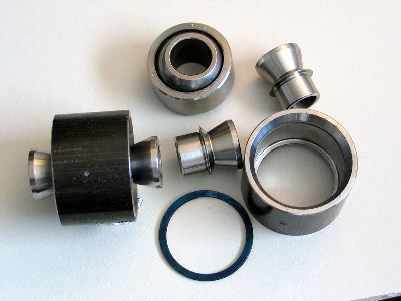
The selection of the joint for the suspension link is at least as important as selection of the tube. Having destroyed countless rubber and poly bushings I am a firm believer in using some sort of cartridge-style joint or spherical rod end (Heim joint). There are many good choices available on the market, all with their advantages and disadvantages. | ||||||||||||||||||||||||||||||||||||||||||||||||||||||||||||||||||||||||||||||||||||||||||||||||||||||||||||||||||||||||||||||||||||||||||||||||||||||||||||||||||||||||||||||||||||||||||||||||||||||||||||||||||||||||||||||||||||||||||||||||||||||||||||||||||||||||||||||||||||||||||||||||||||||||||||||||||||||||||||||||||||||||||||||||||||||||||||||||||||||||||||||||||||||||||||||||||||||||||||||||||||||||||||||||||||||||||||||||||||||||||||||||||||||||||||||||||||||||||||||||||||||||||||||||||||||||||||||||||||||||||||||||||||||||||||||||||||||||||||||||||||||||||||||||||||||||||||||||||||||||||||||||||||||||||||||||||||||||||||||||||||||||||||||||||||||||||||||||||||||||||||||||||||||||||||||||||||||
In selection a joint, there are a number of factors to consider:
|
|||||||||||||||||||||||||||||||||||||||||||||||||||||||||||||||||||||||||||||||||||||||||||||||||||||||||||||||||||||||||||||||||||||||||||||||||||||||||||||||||||||||||||||||||||||||||||||||||||||||||||||||||||||||||||||||||||||||||||||||||||||||||||||||||||||||||||||||||||||||||||||||||||||||||||||||||||||||||||||||||||||||||||||||||||||||||||||||||||||||||||||||||||||||||||||||||||||||||||||||||||||||||||||||||||||||||||||||||||||||||||||||||||||||||||||||||||||||||||||||||||||||||||||||||||||||||||||||||||||||||||||||||||||||||||||||||||||||||||||||||||||||||||||||||||||||||||||||||||||||||||||||||||||||||||||||||||||||||||||||||||||||||||||||||||||||||||||||||||||||||||||||||||||||||||||||||||||||
 |
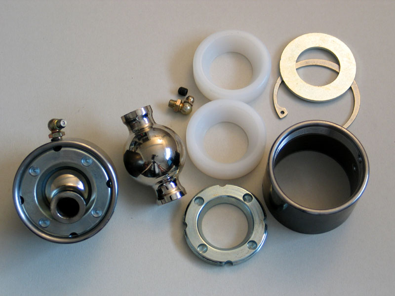
Poly Performance Uniball | ||||||||||||||||||||||||||||||||||||||||||||||||||||||||||||||||||||||||||||||||||||||||||||||||||||||||||||||||||||||||||||||||||||||||||||||||||||||||||||||||||||||||||||||||||||||||||||||||||||||||||||||||||||||||||||||||||||||||||||||||||||||||||||||||||||||||||||||||||||||||||||||||||||||||||||||||||||||||||||||||||||||||||||||||||||||||||||||||||||||||||||||||||||||||||||||||||||||||||||||||||||||||||||||||||||||||||||||||||||||||||||||||||||||||||||||||||||||||||||||||||||||||||||||||||||||||||||||||||||||||||||||||||||||||||||||||||||||||||||||||||||||||||||||||||||||||||||||||||||||||||||||||||||||||||||||||||||||||||||||||||||||||||||||||||||||||||||||||||||||||||||||||||||||||||||||||||||||
 |
Large RE bearing | ||||||||||||||||||||||||||||||||||||||||||||||||||||||||||||||||||||||||||||||||||||||||||||||||||||||||||||||||||||||||||||||||||||||||||||||||||||||||||||||||||||||||||||||||||||||||||||||||||||||||||||||||||||||||||||||||||||||||||||||||||||||||||||||||||||||||||||||||||||||||||||||||||||||||||||||||||||||||||||||||||||||||||||||||||||||||||||||||||||||||||||||||||||||||||||||||||||||||||||||||||||||||||||||||||||||||||||||||||||||||||||||||||||||||||||||||||||||||||||||||||||||||||||||||||||||||||||||||||||||||||||||||||||||||||||||||||||||||||||||||||||||||||||||||||||||||||||||||||||||||||||||||||||||||||||||||||||||||||||||||||||||||||||||||||||||||||||||||||||||||||||||||||||||||||||||||||||||
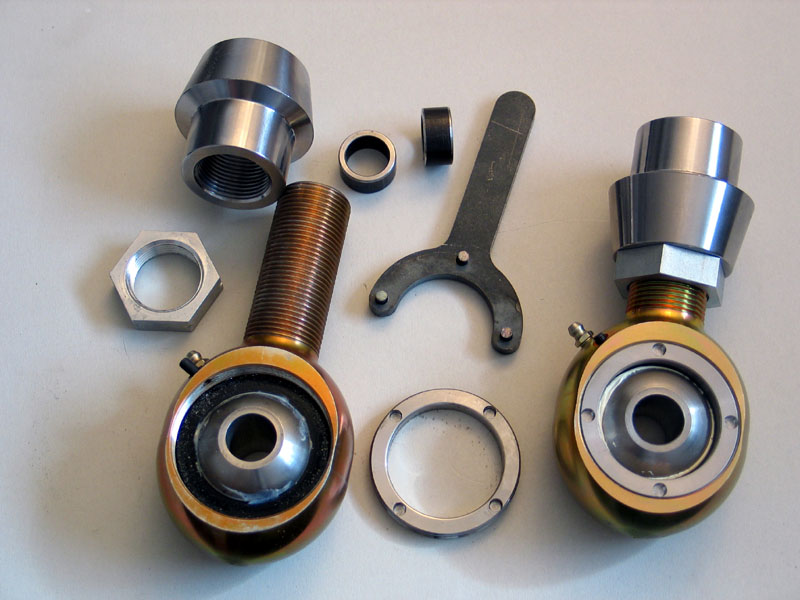 |
Evolution Heim Joint | ||||||||||||||||||||||||||||||||||||||||||||||||||||||||||||||||||||||||||||||||||||||||||||||||||||||||||||||||||||||||||||||||||||||||||||||||||||||||||||||||||||||||||||||||||||||||||||||||||||||||||||||||||||||||||||||||||||||||||||||||||||||||||||||||||||||||||||||||||||||||||||||||||||||||||||||||||||||||||||||||||||||||||||||||||||||||||||||||||||||||||||||||||||||||||||||||||||||||||||||||||||||||||||||||||||||||||||||||||||||||||||||||||||||||||||||||||||||||||||||||||||||||||||||||||||||||||||||||||||||||||||||||||||||||||||||||||||||||||||||||||||||||||||||||||||||||||||||||||||||||||||||||||||||||||||||||||||||||||||||||||||||||||||||||||||||||||||||||||||||||||||||||||||||||||||||||||||||
For a detailed article on joint selection see my article "A Joint for Any Occasion" Link Design FeaturesAs previously mentioned, I am a fan of the simple straight link. However, you may prefer to more highly customize your links. Two common approaches are 1) offset mounting to the joint and 2) links that are pre-bent or curved for clearance. If you decide to design links with such features, there are a couple of "gotchas" to watch out for. If you decide to gain extra clearance by joining the link more towards the top of the joint than to the center, be aware that you will have to adjust the notch in your tube accordingly and that you may further reduce the maximum size of the tube you can use. Of course, if you use a threaded, adjustable joint this will not be an option. I am not a fan of “bent links” because the design either requires bracing which then eats up any previously gained clearance, or leaves the link significantly weaker than if it were not bent. A curved link shifts the neutral axis from the gravity axis (straight line between the ends of the link) toward the center of curvature (the concave side of the link). This shift in the position of the neutral axis causes an increase in the stress on the concave side of the link - up to as much as 3.5 times the stress in a straight link. What does this means in real-world terms? It means, depending on how curved the link is, a bent-link design may require a massive 2-3/4 x ½” tube, weighing over 12 lbs/ft to equal the strength of a 1-3/4 x ¼” straight link that would weigh only 4 lbs/ft. In other words – three times the weight and almost twice the diameter! Building the LinksThe simplest kind of link to build is one that uses, at both ends, joints with threaded shanks and slip-in threaded tube adapters. In this case, you only need to cut the tube to length, insert and weld in the threaded adapters, screw in the joints and you’re finished. When measuring the tube, you will, of course, have to account for the length of the tube adapter, shank of the joint, and distance from shank to bolt hole. When doing so, do not make the mistake of counting the entire length of the threaded shank. I will normally measure the length of the threaded shank, then subtract the length of the threads not available for adjustment. This is equal to the length of the minimum number of engaged threads (calculated as the length of the adapters internal threads plus 3-4 threads) and the length of the threads taken by the jam nut. The resulting number is the length of threads available for adjustment, which I then divide by two, using the resulting figure for the calculation of link length – this allows me to essentially install the link in the middle of its adjustable range so that I can later make it shorter or longer as required. At the other end of the scale is a fixed link with both joints welded directly to the tube. This approach has the advantage of strength and simplicity, but requires extremely careful and accurate measurement and triple-checking as there is no ability to adjust the lengths after construction. Mismatched or inaccurate link lengths will effect steering geometry, suspension performance, and pinion angles – so great care is required. |
|||||||||||||||||||||||||||||||||||||||||||||||||||||||||||||||||||||||||||||||||||||||||||||||||||||||||||||||||||||||||||||||||||||||||||||||||||||||||||||||||||||||||||||||||||||||||||||||||||||||||||||||||||||||||||||||||||||||||||||||||||||||||||||||||||||||||||||||||||||||||||||||||||||||||||||||||||||||||||||||||||||||||||||||||||||||||||||||||||||||||||||||||||||||||||||||||||||||||||||||||||||||||||||||||||||||||||||||||||||||||||||||||||||||||||||||||||||||||||||||||||||||||||||||||||||||||||||||||||||||||||||||||||||||||||||||||||||||||||||||||||||||||||||||||||||||||||||||||||||||||||||||||||||||||||||||||||||||||||||||||||||||||||||||||||||||||||||||||||||||||||||||||||||||||||||||||||||||
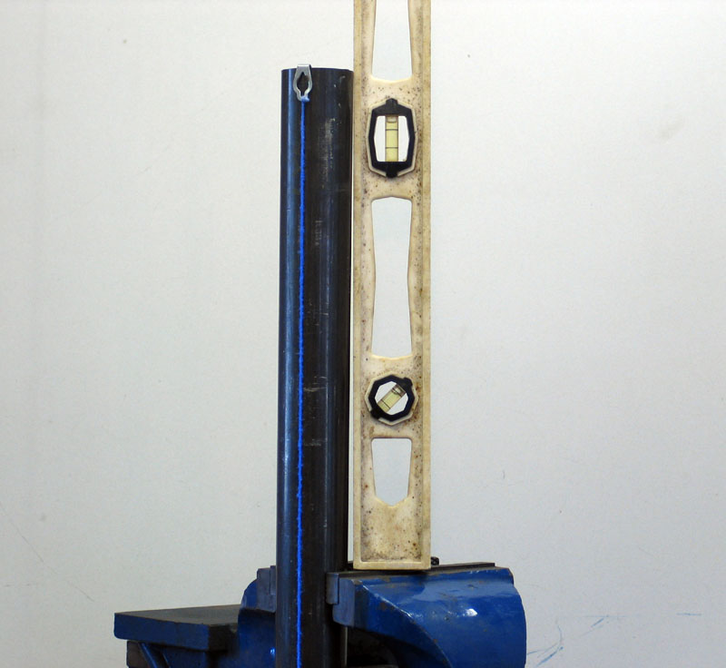 |
Figure 1 – Using a level and plumb-line to mark tube centerline | ||||||||||||||||||||||||||||||||||||||||||||||||||||||||||||||||||||||||||||||||||||||||||||||||||||||||||||||||||||||||||||||||||||||||||||||||||||||||||||||||||||||||||||||||||||||||||||||||||||||||||||||||||||||||||||||||||||||||||||||||||||||||||||||||||||||||||||||||||||||||||||||||||||||||||||||||||||||||||||||||||||||||||||||||||||||||||||||||||||||||||||||||||||||||||||||||||||||||||||||||||||||||||||||||||||||||||||||||||||||||||||||||||||||||||||||||||||||||||||||||||||||||||||||||||||||||||||||||||||||||||||||||||||||||||||||||||||||||||||||||||||||||||||||||||||||||||||||||||||||||||||||||||||||||||||||||||||||||||||||||||||||||||||||||||||||||||||||||||||||||||||||||||||||||||||||||||||||
The other tricky part of making a fixed link with joints welded to both ends is that you have to get both joints at exactly 90° to the tube, and both in the same plane. If not, you will either eat up precious misalignment just to install the link, or worse, not be able to install it at all. Figure 1 illustrates the method I used to mark the tube centerline for my fixed-length, lower, front links. First, clamp the tube in a vice and use a level to make sure it is vertical both side-to-side and front-to-back. Next, use a carpenter’s chalk line to mark a plumb centerline on the tube. Using this centerline as a reference point should allow you to notch the tube so that both joints will be square to the tube and in the same plane. Notching the tube is the final challenge before welding up the links. There are three basic methods for notching tube: tube notcher, chop-saw, and template. Using a tube notcher is the most obvious method – providing you have one. The only caution is that many notcher’s may have a difficult time getting through two inch diameter, half-inch wall tubing. If you use a hole-saw type notcher, be particularly careful of it catching in the cut and trying to break your wrists. With a little patience and practice, you can cut excellent notches in tube using a chop saw. The first step is to mark the centerline of the tube in 2 places exactly 180° apart. Next, set the required angle on your chop saw and chuck the tube in the saw with the blade just touching the first centerline mark (Fig 2). Make the cut (fig 3), and the tube should then look like fig 4. Next, rotate the tube in the saw 180° until the blade just touches the opposite centerline mark (fig 5). Make the final cut, and you will be left with 2 small slivers of tube and a well-formed notch for joining to another tube (fig 6 & fig 8). To make quality, accurate cuts you need to use a decent chop saw with a fairly rigid base and vice, and to use a quality abrasive cutting wheel designed for cutting tube. I prefer Walter brand cutting wheels as they are good quality, last well, and indicate on them with a little icon whether they are suited to cutting tube. The key to success with this method is how accurately you calculate and make the two cuts. Figure 9 illustrates the angle you are setting, and Table 3 gives some values for the cut angle for various sizes of tube. Generally, the larger the angle, the deeper and more narrow the notch. Figure 6 shows a notch cut at 30° and figure 7 shows a notch cut at 45°. Because all chop saws will vary a little and even the best are only capable of limited accuracy in angles the best results will be obtained from using the values in the table as a starting point and then proceeding to practice with your actual tube, keeping a 4.5” angle grinder handy to clean up the notches. After the initial cuts, test-fit the tubes and make any required touch-ups to the notch with the grinder (fig 8). Note that the values in Table 3 are for joining two tubes at 90° to one another. If you want to join the two tubes at an angle (either to offset the link from the joint, or more likely in other tube work such as roll-cage building) you must adjust your cuts as follows. Take the angle at which you want to joint the two tubes, and then modify the initial cut angles by adding this value to one, and subtracting it from the other. For example, if I wanted to join a 2” tube to a 2” tube, the initial cut angle is 30°. If I wanted to join the tubes at a 15° angle, I would add 15° to one cut and subtract it from the other. In this way I would make one cut at 45° and the other at 15°. The values in the table were calculated and kindly provided to me by Marc "Tigweld" Googer. Marc notes that the figures given are for .120" wall tubing and that wall thickness can dramatically affect fit. Thicker walled tube will require either an adjustemnt to the figures shown or some post-cut cleanup with the angle grinder. The only limitation to the chop saw method of tube notching is the angle-capacity of the chop saw – most do not cut angles greater than 45°. NEVER ever be tempted to bypass the chop saw’s vice and simply hold the tube at a steep angle – no matter how strong you think you are there is a very good chance the blade will bind in the cut, rip the tube from your hands, possibly taking finger tips with it, and fling it across the shop with frightening force - as usual - ask me how I know this!. If in doubt about the angle to use, it is best to cut a little shallow (smaller angle) and finish the notch with a hand-held angle grinder. Table 3 - cut angle for various sizes of tube(Data kindly provided by Marc "Tigweld" Googer)
|
|||||||||||||||||||||||||||||||||||||||||||||||||||||||||||||||||||||||||||||||||||||||||||||||||||||||||||||||||||||||||||||||||||||||||||||||||||||||||||||||||||||||||||||||||||||||||||||||||||||||||||||||||||||||||||||||||||||||||||||||||||||||||||||||||||||||||||||||||||||||||||||||||||||||||||||||||||||||||||||||||||||||||||||||||||||||||||||||||||||||||||||||||||||||||||||||||||||||||||||||||||||||||||||||||||||||||||||||||||||||||||||||||||||||||||||||||||||||||||||||||||||||||||||||||||||||||||||||||||||||||||||||||||||||||||||||||||||||||||||||||||||||||||||||||||||||||||||||||||||||||||||||||||||||||||||||||||||||||||||||||||||||||||||||||||||||||||||||||||||||||||||||||||||||||||||||||||||||
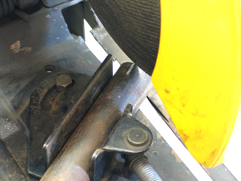 |
Figure 2 – aligning first cut. | ||||||||||||||||||||||||||||||||||||||||||||||||||||||||||||||||||||||||||||||||||||||||||||||||||||||||||||||||||||||||||||||||||||||||||||||||||||||||||||||||||||||||||||||||||||||||||||||||||||||||||||||||||||||||||||||||||||||||||||||||||||||||||||||||||||||||||||||||||||||||||||||||||||||||||||||||||||||||||||||||||||||||||||||||||||||||||||||||||||||||||||||||||||||||||||||||||||||||||||||||||||||||||||||||||||||||||||||||||||||||||||||||||||||||||||||||||||||||||||||||||||||||||||||||||||||||||||||||||||||||||||||||||||||||||||||||||||||||||||||||||||||||||||||||||||||||||||||||||||||||||||||||||||||||||||||||||||||||||||||||||||||||||||||||||||||||||||||||||||||||||||||||||||||||||||||||||||||
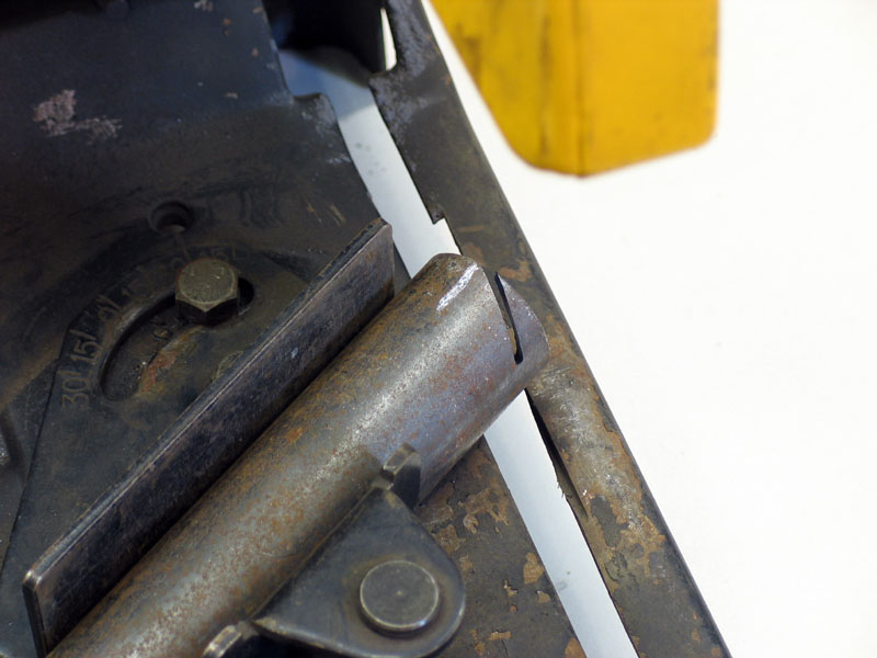 |
Figure 3 – first cut in progress. | ||||||||||||||||||||||||||||||||||||||||||||||||||||||||||||||||||||||||||||||||||||||||||||||||||||||||||||||||||||||||||||||||||||||||||||||||||||||||||||||||||||||||||||||||||||||||||||||||||||||||||||||||||||||||||||||||||||||||||||||||||||||||||||||||||||||||||||||||||||||||||||||||||||||||||||||||||||||||||||||||||||||||||||||||||||||||||||||||||||||||||||||||||||||||||||||||||||||||||||||||||||||||||||||||||||||||||||||||||||||||||||||||||||||||||||||||||||||||||||||||||||||||||||||||||||||||||||||||||||||||||||||||||||||||||||||||||||||||||||||||||||||||||||||||||||||||||||||||||||||||||||||||||||||||||||||||||||||||||||||||||||||||||||||||||||||||||||||||||||||||||||||||||||||||||||||||||||||
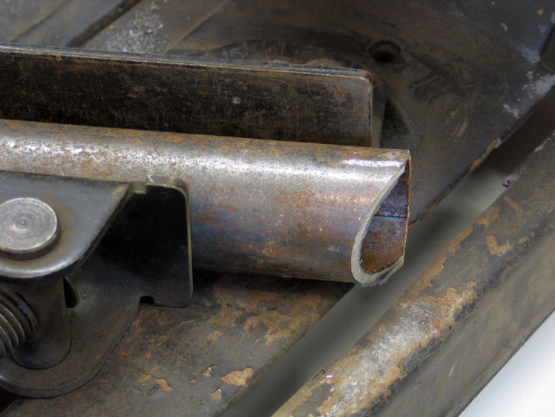 |
Figure 4 – First cut completed. | ||||||||||||||||||||||||||||||||||||||||||||||||||||||||||||||||||||||||||||||||||||||||||||||||||||||||||||||||||||||||||||||||||||||||||||||||||||||||||||||||||||||||||||||||||||||||||||||||||||||||||||||||||||||||||||||||||||||||||||||||||||||||||||||||||||||||||||||||||||||||||||||||||||||||||||||||||||||||||||||||||||||||||||||||||||||||||||||||||||||||||||||||||||||||||||||||||||||||||||||||||||||||||||||||||||||||||||||||||||||||||||||||||||||||||||||||||||||||||||||||||||||||||||||||||||||||||||||||||||||||||||||||||||||||||||||||||||||||||||||||||||||||||||||||||||||||||||||||||||||||||||||||||||||||||||||||||||||||||||||||||||||||||||||||||||||||||||||||||||||||||||||||||||||||||||||||||||||
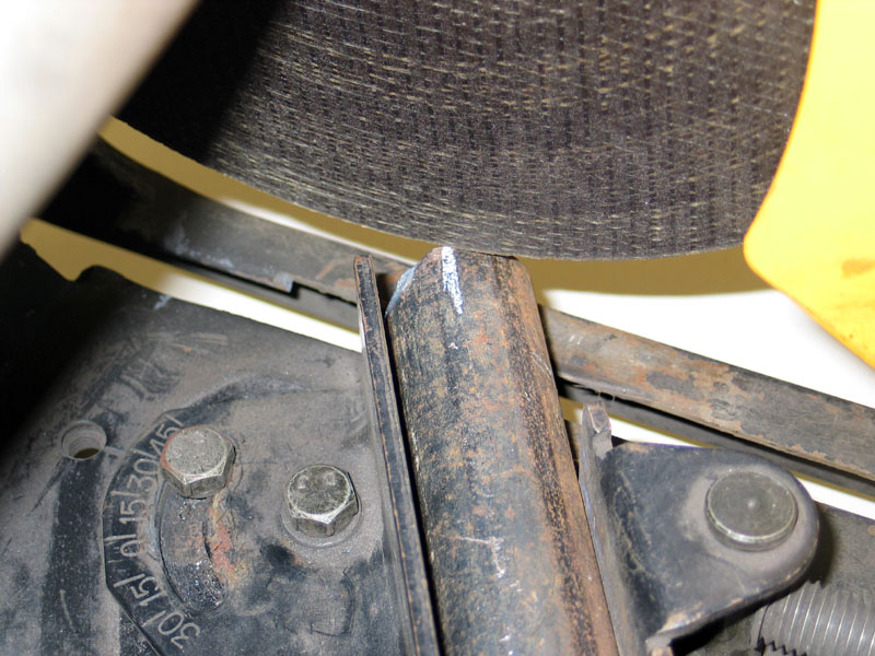 |
Figure 5 – start of second cut | ||||||||||||||||||||||||||||||||||||||||||||||||||||||||||||||||||||||||||||||||||||||||||||||||||||||||||||||||||||||||||||||||||||||||||||||||||||||||||||||||||||||||||||||||||||||||||||||||||||||||||||||||||||||||||||||||||||||||||||||||||||||||||||||||||||||||||||||||||||||||||||||||||||||||||||||||||||||||||||||||||||||||||||||||||||||||||||||||||||||||||||||||||||||||||||||||||||||||||||||||||||||||||||||||||||||||||||||||||||||||||||||||||||||||||||||||||||||||||||||||||||||||||||||||||||||||||||||||||||||||||||||||||||||||||||||||||||||||||||||||||||||||||||||||||||||||||||||||||||||||||||||||||||||||||||||||||||||||||||||||||||||||||||||||||||||||||||||||||||||||||||||||||||||||||||||||||||||
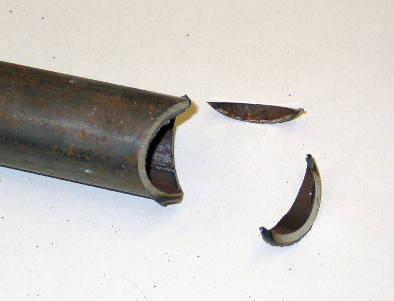 |
Figure 6 – Completed chop saw notch cut at 30° | ||||||||||||||||||||||||||||||||||||||||||||||||||||||||||||||||||||||||||||||||||||||||||||||||||||||||||||||||||||||||||||||||||||||||||||||||||||||||||||||||||||||||||||||||||||||||||||||||||||||||||||||||||||||||||||||||||||||||||||||||||||||||||||||||||||||||||||||||||||||||||||||||||||||||||||||||||||||||||||||||||||||||||||||||||||||||||||||||||||||||||||||||||||||||||||||||||||||||||||||||||||||||||||||||||||||||||||||||||||||||||||||||||||||||||||||||||||||||||||||||||||||||||||||||||||||||||||||||||||||||||||||||||||||||||||||||||||||||||||||||||||||||||||||||||||||||||||||||||||||||||||||||||||||||||||||||||||||||||||||||||||||||||||||||||||||||||||||||||||||||||||||||||||||||||||||||||||||
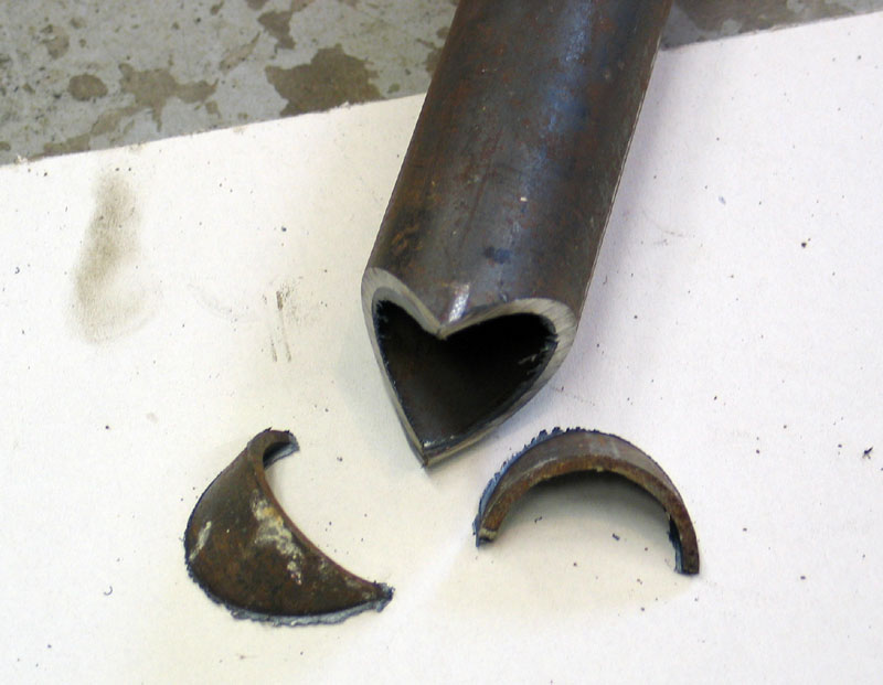 |
Figure 7 – Chop saw notch cut at 45° | ||||||||||||||||||||||||||||||||||||||||||||||||||||||||||||||||||||||||||||||||||||||||||||||||||||||||||||||||||||||||||||||||||||||||||||||||||||||||||||||||||||||||||||||||||||||||||||||||||||||||||||||||||||||||||||||||||||||||||||||||||||||||||||||||||||||||||||||||||||||||||||||||||||||||||||||||||||||||||||||||||||||||||||||||||||||||||||||||||||||||||||||||||||||||||||||||||||||||||||||||||||||||||||||||||||||||||||||||||||||||||||||||||||||||||||||||||||||||||||||||||||||||||||||||||||||||||||||||||||||||||||||||||||||||||||||||||||||||||||||||||||||||||||||||||||||||||||||||||||||||||||||||||||||||||||||||||||||||||||||||||||||||||||||||||||||||||||||||||||||||||||||||||||||||||||||||||||||
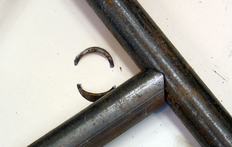 |
Fig 8 – Test fitting the notch | ||||||||||||||||||||||||||||||||||||||||||||||||||||||||||||||||||||||||||||||||||||||||||||||||||||||||||||||||||||||||||||||||||||||||||||||||||||||||||||||||||||||||||||||||||||||||||||||||||||||||||||||||||||||||||||||||||||||||||||||||||||||||||||||||||||||||||||||||||||||||||||||||||||||||||||||||||||||||||||||||||||||||||||||||||||||||||||||||||||||||||||||||||||||||||||||||||||||||||||||||||||||||||||||||||||||||||||||||||||||||||||||||||||||||||||||||||||||||||||||||||||||||||||||||||||||||||||||||||||||||||||||||||||||||||||||||||||||||||||||||||||||||||||||||||||||||||||||||||||||||||||||||||||||||||||||||||||||||||||||||||||||||||||||||||||||||||||||||||||||||||||||||||||||||||||||||||||||
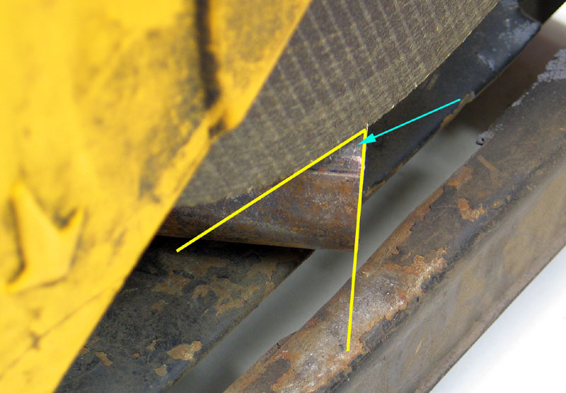 |
Fig 9 – cut angle for chop saw notching | ||||||||||||||||||||||||||||||||||||||||||||||||||||||||||||||||||||||||||||||||||||||||||||||||||||||||||||||||||||||||||||||||||||||||||||||||||||||||||||||||||||||||||||||||||||||||||||||||||||||||||||||||||||||||||||||||||||||||||||||||||||||||||||||||||||||||||||||||||||||||||||||||||||||||||||||||||||||||||||||||||||||||||||||||||||||||||||||||||||||||||||||||||||||||||||||||||||||||||||||||||||||||||||||||||||||||||||||||||||||||||||||||||||||||||||||||||||||||||||||||||||||||||||||||||||||||||||||||||||||||||||||||||||||||||||||||||||||||||||||||||||||||||||||||||||||||||||||||||||||||||||||||||||||||||||||||||||||||||||||||||||||||||||||||||||||||||||||||||||||||||||||||||||||||||||||||||||||
| The third method for notching a tube is to use a computer program that will allow you to enter the tube dimensions and will then calculate and print a template for your notch. You can then cut out this template, trace it onto the tube, and use any of several methods to cut along the lines of the notch (chop saw, 4.5” angle grinder with cutting disc, plasma cutter, etc.) Depending on how rough your cutting was, you can then clean up the notch with a 4.5” angle grinder to get a perfect fit. One such program available on the internet is Winmiter. It is a shareware program originally written for bicycle building enthusiasts. It accepts inputs of: large tube diameter, small tube diameter, angle of joint, and centerline offset, in metric or imperial units. It will then compute and display and/or print a simple template. I used this method for notching the 2” x 3/8” tube for my front lower links and it worked fairly well. Fig 10 shows the template cut out and taped to the tube, ready to be traced. After cutting the notch with a plasma cutter I then used a grinder to clean it up, pausing periodically to check the fit (fig 11). | |||||||||||||||||||||||||||||||||||||||||||||||||||||||||||||||||||||||||||||||||||||||||||||||||||||||||||||||||||||||||||||||||||||||||||||||||||||||||||||||||||||||||||||||||||||||||||||||||||||||||||||||||||||||||||||||||||||||||||||||||||||||||||||||||||||||||||||||||||||||||||||||||||||||||||||||||||||||||||||||||||||||||||||||||||||||||||||||||||||||||||||||||||||||||||||||||||||||||||||||||||||||||||||||||||||||||||||||||||||||||||||||||||||||||||||||||||||||||||||||||||||||||||||||||||||||||||||||||||||||||||||||||||||||||||||||||||||||||||||||||||||||||||||||||||||||||||||||||||||||||||||||||||||||||||||||||||||||||||||||||||||||||||||||||||||||||||||||||||||||||||||||||||||||||||||||||||||||
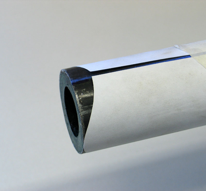 |
Fig 10 – Winmiter template taped to 2” tube | ||||||||||||||||||||||||||||||||||||||||||||||||||||||||||||||||||||||||||||||||||||||||||||||||||||||||||||||||||||||||||||||||||||||||||||||||||||||||||||||||||||||||||||||||||||||||||||||||||||||||||||||||||||||||||||||||||||||||||||||||||||||||||||||||||||||||||||||||||||||||||||||||||||||||||||||||||||||||||||||||||||||||||||||||||||||||||||||||||||||||||||||||||||||||||||||||||||||||||||||||||||||||||||||||||||||||||||||||||||||||||||||||||||||||||||||||||||||||||||||||||||||||||||||||||||||||||||||||||||||||||||||||||||||||||||||||||||||||||||||||||||||||||||||||||||||||||||||||||||||||||||||||||||||||||||||||||||||||||||||||||||||||||||||||||||||||||||||||||||||||||||||||||||||||||||||||||||||
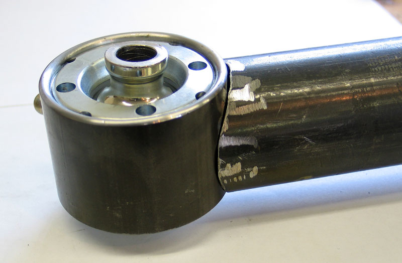 |
Figure 11 – 2” tube being test fit with RE bearing | ||||||||||||||||||||||||||||||||||||||||||||||||||||||||||||||||||||||||||||||||||||||||||||||||||||||||||||||||||||||||||||||||||||||||||||||||||||||||||||||||||||||||||||||||||||||||||||||||||||||||||||||||||||||||||||||||||||||||||||||||||||||||||||||||||||||||||||||||||||||||||||||||||||||||||||||||||||||||||||||||||||||||||||||||||||||||||||||||||||||||||||||||||||||||||||||||||||||||||||||||||||||||||||||||||||||||||||||||||||||||||||||||||||||||||||||||||||||||||||||||||||||||||||||||||||||||||||||||||||||||||||||||||||||||||||||||||||||||||||||||||||||||||||||||||||||||||||||||||||||||||||||||||||||||||||||||||||||||||||||||||||||||||||||||||||||||||||||||||||||||||||||||||||||||||||||||||||||
| The final step in joining your links to non-thread-in joints is to weld. The Evolution tube inserts come with a generous bevel (fig 12) allowing for a good strong weld (fig 13). If welding a tube directly to the body of a joint, make sure you have a good, clean, tight fit. Fig 11 shows a 2” tube being test fit to a RE joint and reveals that a little more grinder work is required on the tube to get the best fit. Patience is the key as a tight fitting assembly will ensure a strong weld and ultimately strong links. | |||||||||||||||||||||||||||||||||||||||||||||||||||||||||||||||||||||||||||||||||||||||||||||||||||||||||||||||||||||||||||||||||||||||||||||||||||||||||||||||||||||||||||||||||||||||||||||||||||||||||||||||||||||||||||||||||||||||||||||||||||||||||||||||||||||||||||||||||||||||||||||||||||||||||||||||||||||||||||||||||||||||||||||||||||||||||||||||||||||||||||||||||||||||||||||||||||||||||||||||||||||||||||||||||||||||||||||||||||||||||||||||||||||||||||||||||||||||||||||||||||||||||||||||||||||||||||||||||||||||||||||||||||||||||||||||||||||||||||||||||||||||||||||||||||||||||||||||||||||||||||||||||||||||||||||||||||||||||||||||||||||||||||||||||||||||||||||||||||||||||||||||||||||||||||||||||||||||
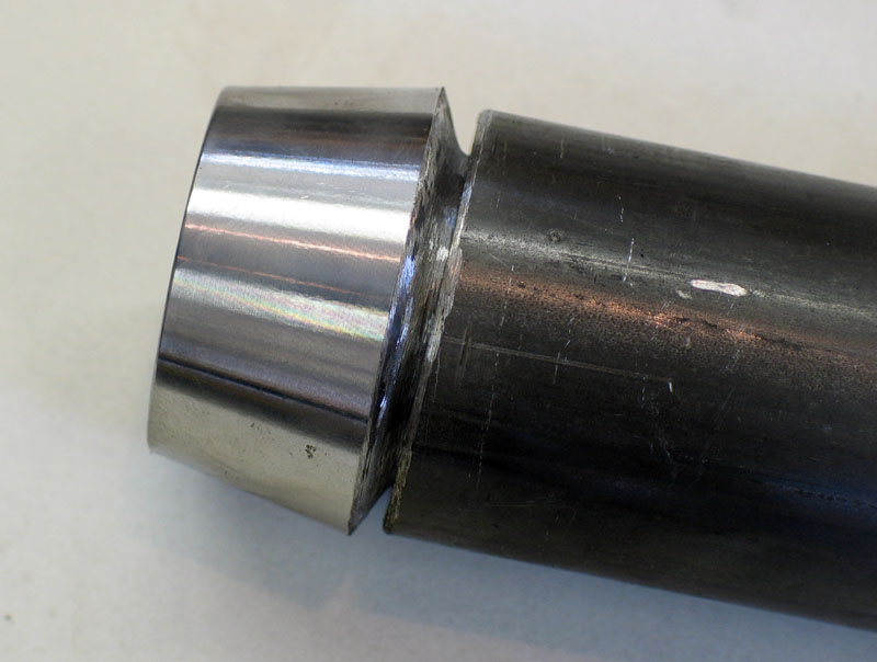 |
Figure 12 – Evolution threaded tube insert in 1.75” ID tube |
||||||||||||||||||||||||||||||||||||||||||||||||||||||||||||||||||||||||||||||||||||||||||||||||||||||||||||||||||||||||||||||||||||||||||||||||||||||||||||||||||||||||||||||||||||||||||||||||||||||||||||||||||||||||||||||||||||||||||||||||||||||||||||||||||||||||||||||||||||||||||||||||||||||||||||||||||||||||||||||||||||||||||||||||||||||||||||||||||||||||||||||||||||||||||||||||||||||||||||||||||||||||||||||||||||||||||||||||||||||||||||||||||||||||||||||||||||||||||||||||||||||||||||||||||||||||||||||||||||||||||||||||||||||||||||||||||||||||||||||||||||||||||||||||||||||||||||||||||||||||||||||||||||||||||||||||||||||||||||||||||||||||||||||||||||||||||||||||||||||||||||||||||||||||||||||||||||||
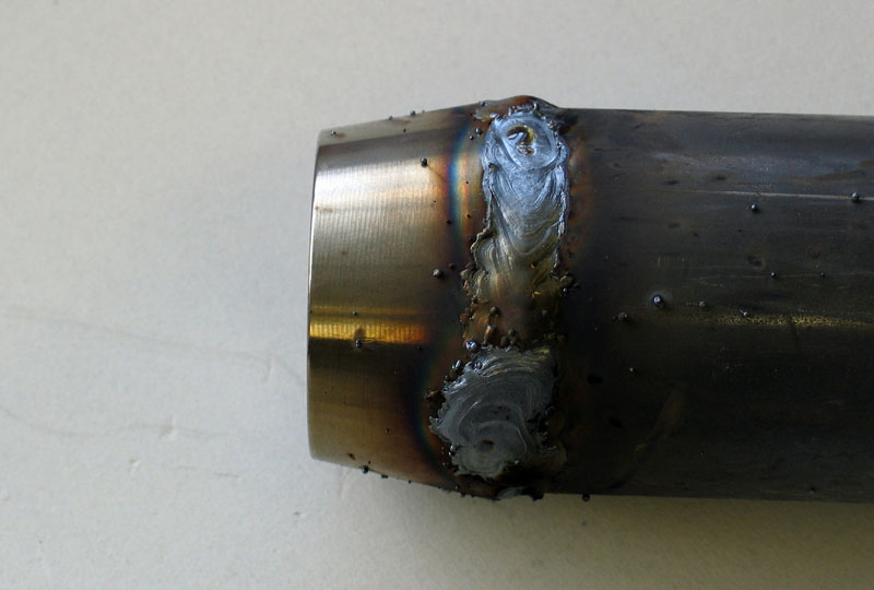 |
Figure 13 – welded tube insert |
||||||||||||||||||||||||||||||||||||||||||||||||||||||||||||||||||||||||||||||||||||||||||||||||||||||||||||||||||||||||||||||||||||||||||||||||||||||||||||||||||||||||||||||||||||||||||||||||||||||||||||||||||||||||||||||||||||||||||||||||||||||||||||||||||||||||||||||||||||||||||||||||||||||||||||||||||||||||||||||||||||||||||||||||||||||||||||||||||||||||||||||||||||||||||||||||||||||||||||||||||||||||||||||||||||||||||||||||||||||||||||||||||||||||||||||||||||||||||||||||||||||||||||||||||||||||||||||||||||||||||||||||||||||||||||||||||||||||||||||||||||||||||||||||||||||||||||||||||||||||||||||||||||||||||||||||||||||||||||||||||||||||||||||||||||||||||||||||||||||||||||||||||||||||||||||||||||||
| Figures 14, 15, and 16 offer a final
look at some of my completed links, built using the products and procedures
described in this article. May you experience the greatest success in your own
projects. Good luck! |
|||||||||||||||||||||||||||||||||||||||||||||||||||||||||||||||||||||||||||||||||||||||||||||||||||||||||||||||||||||||||||||||||||||||||||||||||||||||||||||||||||||||||||||||||||||||||||||||||||||||||||||||||||||||||||||||||||||||||||||||||||||||||||||||||||||||||||||||||||||||||||||||||||||||||||||||||||||||||||||||||||||||||||||||||||||||||||||||||||||||||||||||||||||||||||||||||||||||||||||||||||||||||||||||||||||||||||||||||||||||||||||||||||||||||||||||||||||||||||||||||||||||||||||||||||||||||||||||||||||||||||||||||||||||||||||||||||||||||||||||||||||||||||||||||||||||||||||||||||||||||||||||||||||||||||||||||||||||||||||||||||||||||||||||||||||||||||||||||||||||||||||||||||||||||||||||||||||||
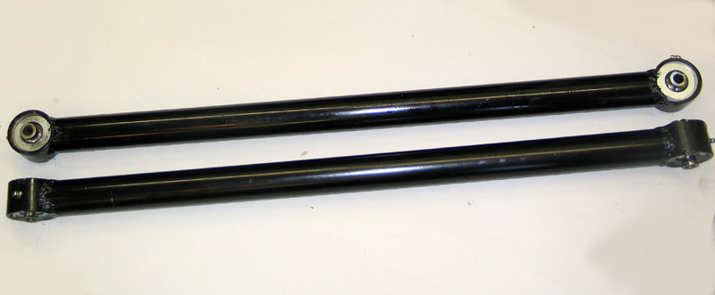 |
Figure 14 – Fixed length lower front links using RE bearings and 2” x 3/8” DOM | ||||||||||||||||||||||||||||||||||||||||||||||||||||||||||||||||||||||||||||||||||||||||||||||||||||||||||||||||||||||||||||||||||||||||||||||||||||||||||||||||||||||||||||||||||||||||||||||||||||||||||||||||||||||||||||||||||||||||||||||||||||||||||||||||||||||||||||||||||||||||||||||||||||||||||||||||||||||||||||||||||||||||||||||||||||||||||||||||||||||||||||||||||||||||||||||||||||||||||||||||||||||||||||||||||||||||||||||||||||||||||||||||||||||||||||||||||||||||||||||||||||||||||||||||||||||||||||||||||||||||||||||||||||||||||||||||||||||||||||||||||||||||||||||||||||||||||||||||||||||||||||||||||||||||||||||||||||||||||||||||||||||||||||||||||||||||||||||||||||||||||||||||||||||||||||||||||||||
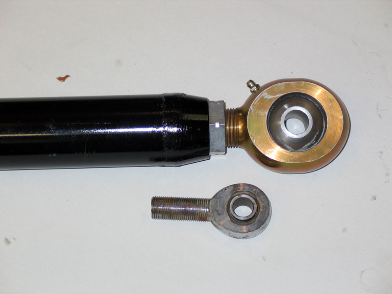 |
Figure 15 –
Completed link with Evolution Joint shown next to standard ¾” Heim joint for scale. |
||||||||||||||||||||||||||||||||||||||||||||||||||||||||||||||||||||||||||||||||||||||||||||||||||||||||||||||||||||||||||||||||||||||||||||||||||||||||||||||||||||||||||||||||||||||||||||||||||||||||||||||||||||||||||||||||||||||||||||||||||||||||||||||||||||||||||||||||||||||||||||||||||||||||||||||||||||||||||||||||||||||||||||||||||||||||||||||||||||||||||||||||||||||||||||||||||||||||||||||||||||||||||||||||||||||||||||||||||||||||||||||||||||||||||||||||||||||||||||||||||||||||||||||||||||||||||||||||||||||||||||||||||||||||||||||||||||||||||||||||||||||||||||||||||||||||||||||||||||||||||||||||||||||||||||||||||||||||||||||||||||||||||||||||||||||||||||||||||||||||||||||||||||||||||||||||||||||
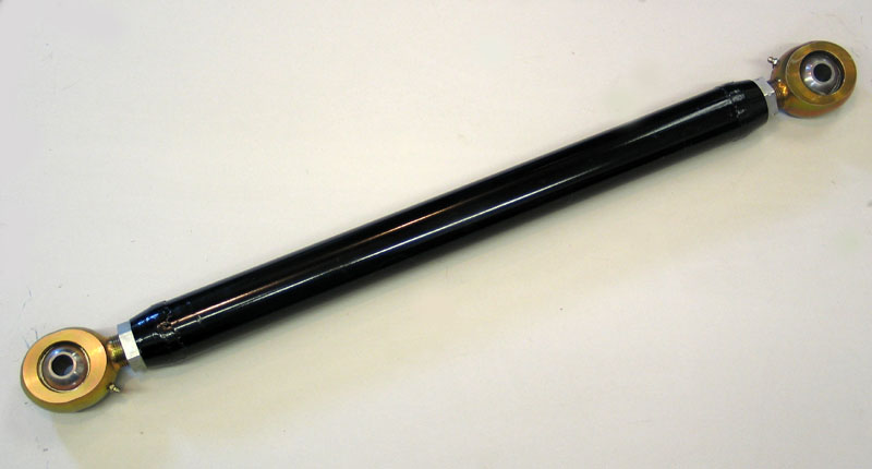 |
Figure 16 – Adjustable top front link using Evolution Joints and 2.25 X ¼” DOM | ||||||||||||||||||||||||||||||||||||||||||||||||||||||||||||||||||||||||||||||||||||||||||||||||||||||||||||||||||||||||||||||||||||||||||||||||||||||||||||||||||||||||||||||||||||||||||||||||||||||||||||||||||||||||||||||||||||||||||||||||||||||||||||||||||||||||||||||||||||||||||||||||||||||||||||||||||||||||||||||||||||||||||||||||||||||||||||||||||||||||||||||||||||||||||||||||||||||||||||||||||||||||||||||||||||||||||||||||||||||||||||||||||||||||||||||||||||||||||||||||||||||||||||||||||||||||||||||||||||||||||||||||||||||||||||||||||||||||||||||||||||||||||||||||||||||||||||||||||||||||||||||||||||||||||||||||||||||||||||||||||||||||||||||||||||||||||||||||||||||||||||||||||||||||||||||||||||||
Addendum:
|
|||||||||||||||||||||||||||||||||||||||||||||||||||||||||||||||||||||||||||||||||||||||||||||||||||||||||||||||||||||||||||||||||||||||||||||||||||||||||||||||||||||||||||||||||||||||||||||||||||||||||||||||||||||||||||||||||||||||||||||||||||||||||||||||||||||||||||||||||||||||||||||||||||||||||||||||||||||||||||||||||||||||||||||||||||||||||||||||||||||||||||||||||||||||||||||||||||||||||||||||||||||||||||||||||||||||||||||||||||||||||||||||||||||||||||||||||||||||||||||||||||||||||||||||||||||||||||||||||||||||||||||||||||||||||||||||||||||||||||||||||||||||||||||||||||||||||||||||||||||||||||||||||||||||||||||||||||||||||||||||||||||||||||||||||||||||||||||||||||||||||||||||||||||||||||||||||||||||
 |
Sources: Evolution
Joints: RE
Bearings & Poly Performance Uniballs: |
|