 |
Teraflex T-Locker By Bill "BillaVista" Ansell |
IntroductionI had long wanted a selectable locker for the front of my rig. While my old welded-up spool provided all the traction I ever wanted, the handling it induced was terrible. The overwhelming tendency for the front wheels to plough straight ahead while turned, seriously compromised manoeuvrability. It was especially annoying in tight, technical rock crawling where precision is key and a few inches can mean making or losing the line. Adding full hydraulic steering did nothing to help – sure, it reduced the steering effort a lot, but it can’t make the wheels track a turn the way an open differential can. I tried various other “solutions” to the problem: I added cutting brakes and I tried using locking hubs instead of drive flanges but nothing stopped the front end from ploughing. And so I knew that if it was the ultimate in both traction and turning I wanted, a selectable locker I must have. But which one? |
 |
There are several choices on the market, differentiated principally by the way in which the locker is activated. I immediately dismissed cable and electrically-activated lockers, as it is difficult for either of these methods to develop sufficient force for the sure, reliable shifting I wanted. Additionally, the locker’s location means constant submersion in water, mud, and goo – making it a not-so-great location for electrical servos. Cable activation would require finicky setup, a large lever for any real power, and likely constant adjustment and maintenance of the cable. This leaves pneumatically or hydraulically activated lockers, but which of these to choose? I’m a big fan of hydraulic power, but it requires specialized pumps and plumbing, and operates at very high pressure. Not only that, but Mercedes Benz make the only manually selectable hydraulic lockers I’m aware of - and only for their own products like the Gelandewagen. So that leaves pneumatic, or air-operated, activation. Fortunately, pneumatics is an excellent solution. The beauty of pneumatics is that the plumbing is simple and cheap, it operates at low pressures (under 100 psi as opposed to 1000+ in hydraulics), and there are virtually limitless options for supplying the air - from small electrical compressors to engine-driven on-board air systems to portable CO2 tanks. Not only that, but most of us will already have some sort of air supply system incorporated into our rigs. A short time ago, when I heard that Tibus Offroad (of Unimog axle fame) were designing a new type of pneumatic locker, I jumped at the chance to install one in my Dana 60, test and review it. Here’s what I found: The T-locker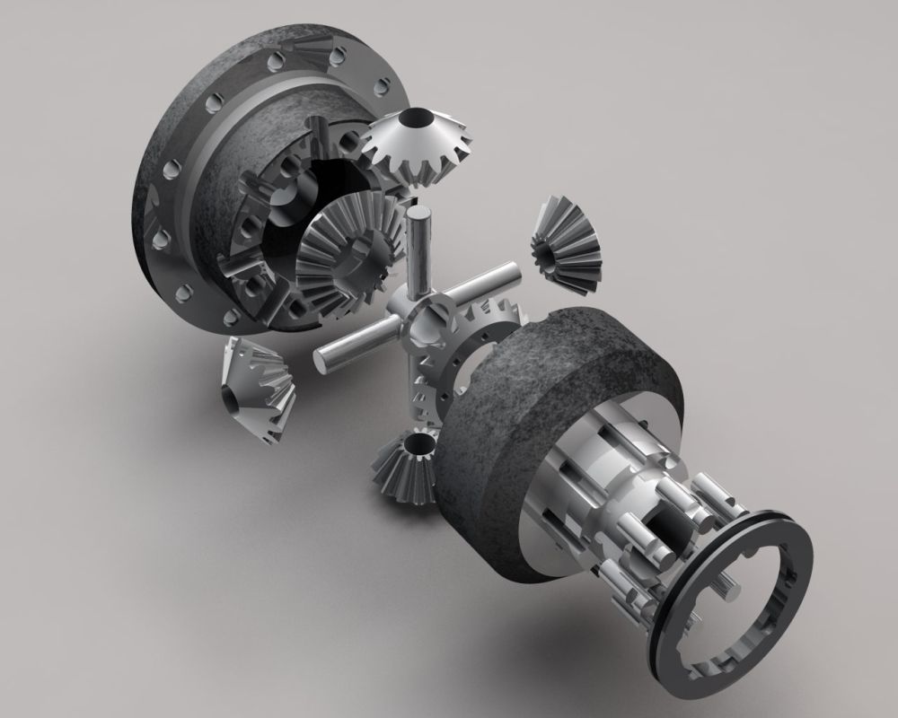 Figure 1 – T-locker exploded view |
|
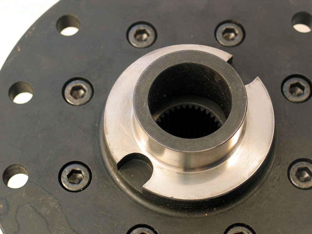 Figure 2 – Carrier bearing reliefs |
The new T-locker is a pneumatically shifted, manually controlled, selectable
locking differential that gives the operator a choice of fully-locked operation
(essentially operating as a spool) or fully-open operation (operating as
a standard open differential).
The T-locker was designed from the ground up by German engineer Wolfgang Tibus to be the strongest, most reliable selectable locker available. The engineering, machining, and fit & finish of the T-locker are absolutely first rate – and this is immediately apparent the second you hold one in your hands. Weighing in at over 35 pounds it’s a serious brute of a machine. Not only that, but there are also several small touches that demonstrate the level of thought and attention to detail that went into its construction. For example, there are very generous reliefs machined into the carrier bearing seats – sure to be appreciated by anyone who’s had to use a twin-leg puller to remove carrier bearings (Figure 2). |
||||
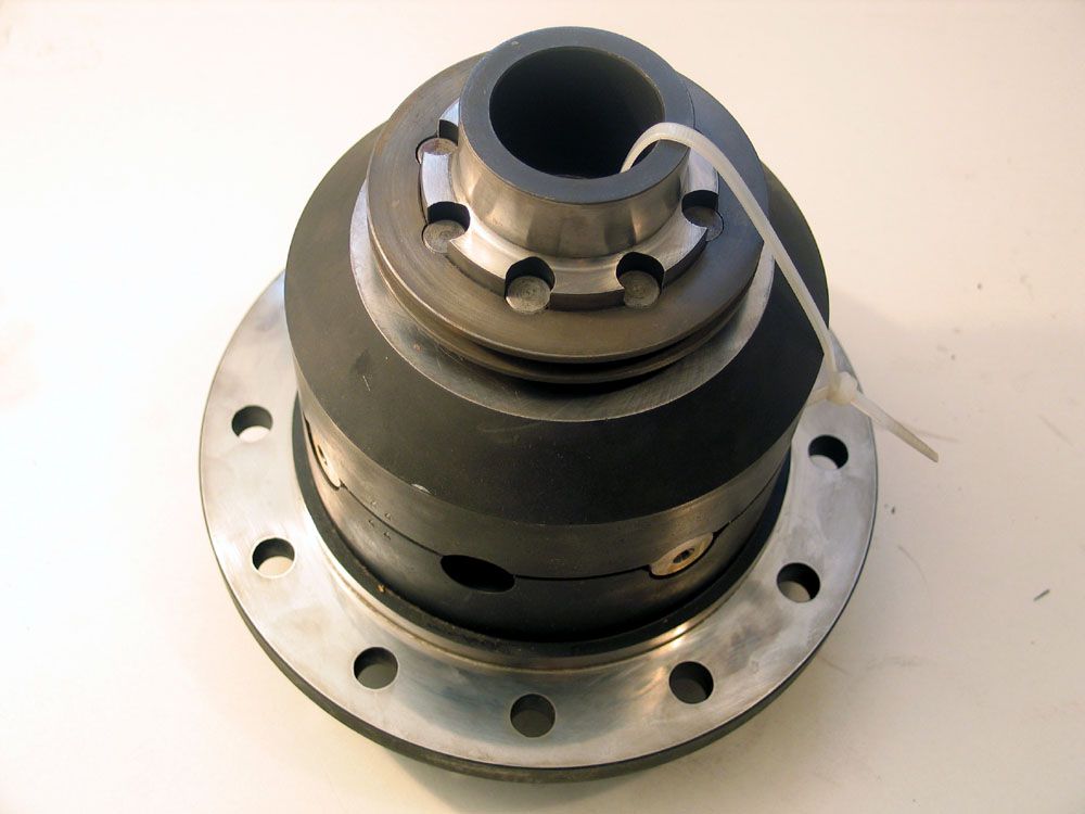
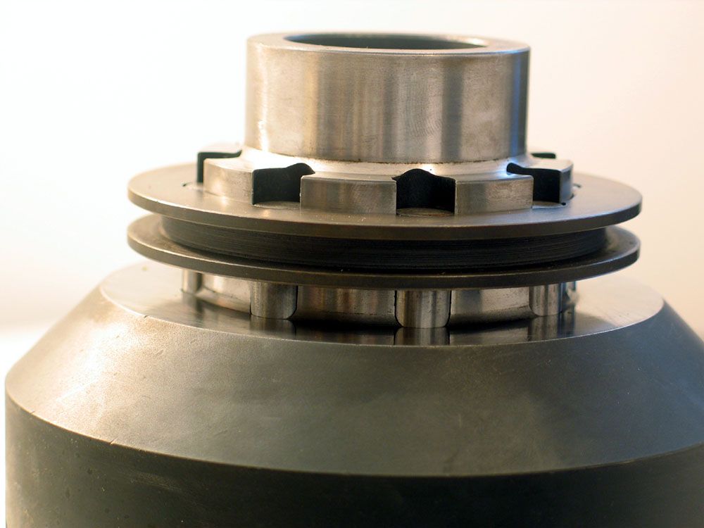 Figure 3 – Shift collar |
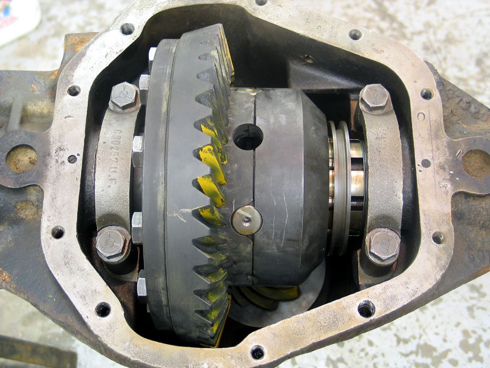
The way that it works is deceptively simple. Figure 1 illustrates an exploded view of the locker. Inside the case there are four spider gears, two side gears, and two cross-pins. The locking ability comes from the fact that one of the side gears is machined to accept eight hardened-steel locking pins. These pins slide in grooves in the case to engage or disengage the side gear. The position of the pins is controlled by a sliding shift collar that sits just below the carrier bearing journal on the non ring-gear side of the case (Figure 3). |
||||
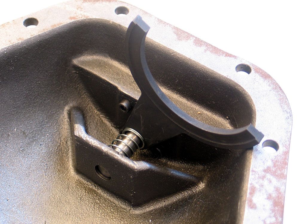 Figure 4 – Shift fork |
The position of the shift collar is in turn controlled by a shift fork that is built into the diff cover (Figure 4). When the shift fork is shifted to the “lock” position, the shift collar slides towards the centre of the case, the pins engage the side gear, the locker is “locked”, and the axle shafts are 100% mechanically locked together giving maximum traction. When the shift fork is shifted to “unlock”, the collar slides away from the centre of the diff , the pins retract from the side gear, the side gear is allowed to turn freely, and the T-locker now behaves as an open differential. The shift fork itself is shifted by a small pneumatic cylinder (very much like a small hydraulic cylinder) that is mounted on the diff cover (Figure 6). | ||||
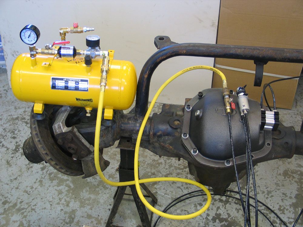 Figure 5 – Complete pneumatic system |
There are
two ports on the pneumatic cylinder, one for lock and one for unlock. Applying
air pressure to one or the other shifts the fork in the desired direction,
meaning the locker is powered in both directions. As such it doesn’t
rely solely on a return spring to unlock, resulting in much more positive
shifting than would otherwise be the case.
There is also a return spring, as can be seen in Figure 4. The purpose of the return spring is to return the shift fork, and therefore the locker, to the desired state, should there be a complete loss of system pressure. I say “desired state” because of one of the great advantages of the T-locker’s design – the user can choose whether the default, pressure-loss position is “locked” or “unlocked”. The factory setting is “unlocked”, and this should never be altered for a street driven rig (imagine tooling along at 50mph with the locker open and experiencing a pressure loss – the return spring would take over and shift the locker to lock with disastrous consequences!) However, in a dedicated trail rig, one can simply install the spring on the other side of the shift fork, causing the pressure-loss position to be “locked” – which may be an advantage where maximum traction is a must. As far as I know – no other locker offers this choice. |
||||
The Pneumatic System |
|||||
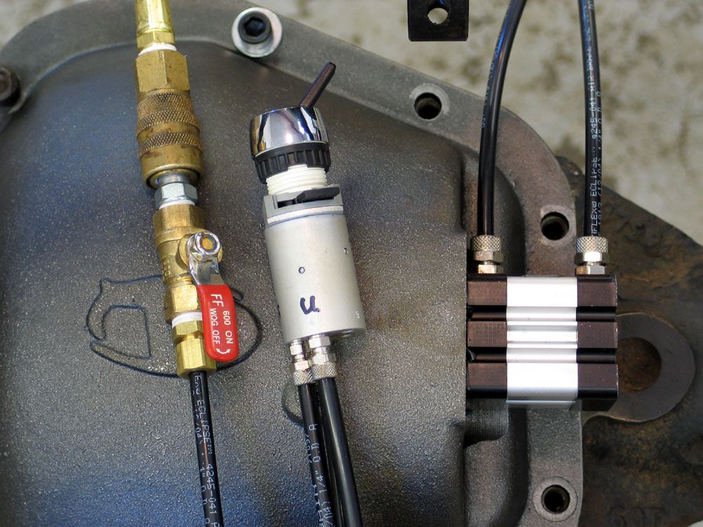 Figure 6 – T-locker switch and cylinder |
That said,
a loss of air pressure is unlikely, and even if it happens, it will be quick
and simple to repair – even on the trail. That’s because the
real beauty of the T-locker lies in the simple, rugged design of the pneumatics.
There are only three components involved: the pneumatic cylinder (built
into the diff cover), the switch (mounted wherever the operator desires),
and a supply of air. Figure 5 shows the complete pneumatic system, from
supply tank to cylinder.
The entire air system lies outside the diff cover. This means that there are no seals on rotating parts to wear or leak, no drilling into housings or bearing caps required, no gear oil will ever blow back up the lines, and the system can be installed, troubleshot, and repaired, even in the field, without ever having to remove the diff cover. Figure 6 illustrates, from left to right: quick-release air supply with shut-off valve, locker activation switch, and pneumatic cylinder with air-lines attached. |
||||
The key to the system is the very clever switch (centre, Figure 6). The switch is actually a mechanically operated, two-position, monostable, pneumatic solenoid valve designed and built by the German company, Joyner Pneumatic (as is the cylinder). What this really means is that it is ingenious! First, there is no electrical wiring involved – the switch is mechanically operated (the user flips a toggle) and pneumatically actuated (only a supply of air is required for operation). Second, there are only three simple air lines – one from the air source to the switch, one from the switch to the “lock“ port on the cylinder, and one from the switch to the “unlock” port on the cylinder. There are five ports on the switch, as follows: 1 – Air supply To port 1 you connect an air supply capable of delivering anywhere from 20-150 psi. Port 2 is connected to the lock port on the cylinder (the outer port), and port 4 is connected to the unlock port on the cylinder (the inner port, closest to the diff). Ports 3 and 5 are vents and are left unconnected. |
|||||
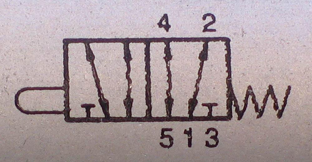 Figure 7 – Pneumatic switch solenoid diagram |
Figure 7 illustrates the solenoid schematic diagram. The diagram shows us that the solenoid is a two-position, push-button activated, spring-loaded switch (similar to a spring-loaded on/off switch). There are two positions for the switch, each represented by a rectangular box in the schematic. The arrows in the boxes show the connections between the numbered ports, depending on which position the switch is in. The box on the right, closest to the spring, shows the connections in the normal (spring relaxed) position, the box on the left shows the connections with the spring compressed. With the switch in “normal” port 1 is connected to port 2, supplying air pressure to the lock side of the cylinder; port 4 is connected to port 5, venting the unlock side and port 3 is internally blocked off (represented by the T). When the operator flips the toggle switch a plunger presses on the activation button, the spring is compressed and the connections become those shown in the box on the left: port 2 is vented to port 3 (releasing the lock side), port 1 is connected to port 4 (pressurizing the unlock side of the cylinder), and port 5 is blocked off. In simple terms, flipping the toggle switch one way pressurizes the lock line and vents the unlock line, flipping it the other way does the reverse. | ||||
It takes very little volume to power the cylinder and activate the locker, and it works with pressure ranging from 20 to 150 psi. Below 20 psi the shifts become a little weak and slow, and greater than 150 psi puts unnecessary stress on the air-lines and cylinder/switch seals. Note that the lock and unlock circuits are completely isolated by having their own vents. This means that a loss of pressure on one side will not affect the other – in other words, if you rip the unlock air-line, the locker will remain locked, and vice versa. In fact, because of this design, if you install a shut-off valve in the air-supply-to-switch line, it is possible to pressurize the desired line (lock or unlock), close the valve in the supply line, and then actually disconnect and remove the air supply completely and the locker will remain in the desired position. Taking this to the extreme, you could actually fit your supply line with a Schrader valve and operate the locker with a small hand-operated bicycle pump! It’s certainly not the recommended method – but it’s nice to know it could be done if required. |
|||||
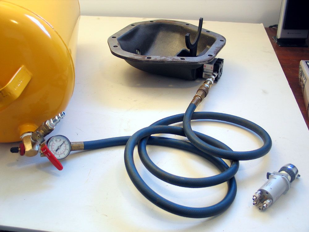 Figure 8 – Pressure and leak testing |
During testing I was able to get the locker to shift all the way down to 10 psi. I also disconnected the air supply and found that the locker requires such a small volume of air for activation that I could lock and unlock it three times with just the volume of air in the lines. To test the air fittings I pressurized the lock line, disconnected the air supply and monitored for leaks (Figure 8). Eleven hours later the line still held pressure, the fork remained firmly locked, and I got tired of watching it! | ||||
Plumbing |
|||||
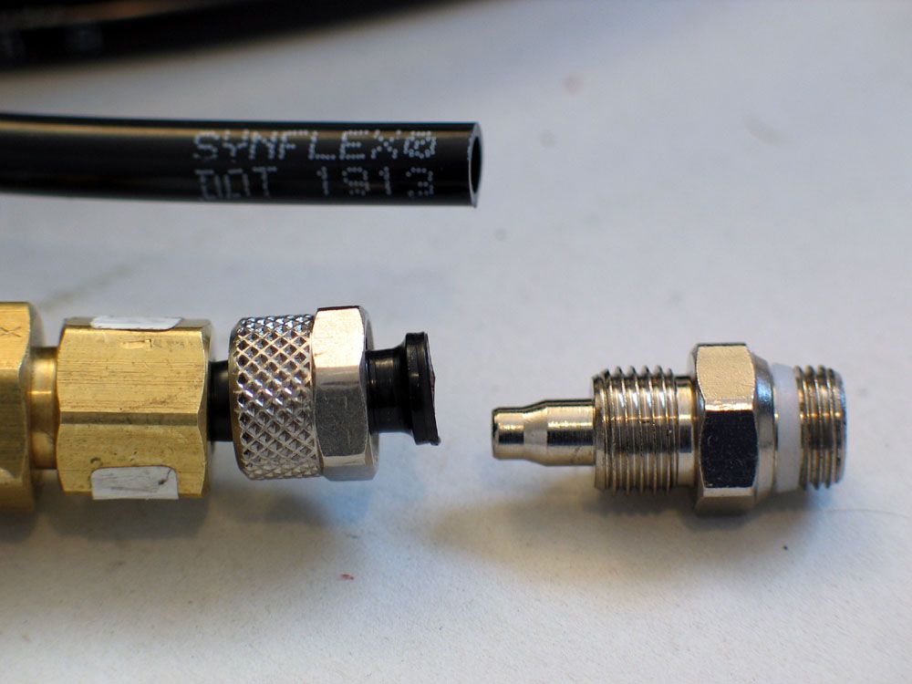 Figure 9 – T-locker air-line fitting |
Possibly the trickest parts of the kit are the air-line fittings (Figure 9). There are two different size fittings, a large one for the cylinder ports and a smaller one for the switch ports. The larger has British Standard Pipe Parallel (BSPP) 1/8” x 28 TPI threads (also called ‘G-1/8” Pipe’, and very common in pneumatics.) The smaller fitting has M5x0.8 mm threads. Both are designed to use either 6x4mm metric or ¼” SAE air line, and both consist of only two parts. The main body threads into the port, the small cap slips over the air line, the air line is pushed onto the nipple on the main body, and the cap is then tightened onto the main body. There is no separate ferrule to lose or risk deforming when the fitting is tightened. When the cap is tightened onto the main body, it creates a sort of “self-flaring” effect on the air-line, resulting in a leak-free connection. After initial installation the line can even be removed and then re-attached, unlike a normal compression fitting that requires replacement of the ferrule. The only thing not included in the kit is the air-line itself. You will need to acquire about 20-30 feet of ¼” SAE J844 Type A or B nylon tubing designed for use in tractor-trailer and other mobile air brake, instrumentation, and air accessory systems. |
||||
It should have a temperature range of about -40°F to +200°F and a working pressure of at least 150 PSI. It is commonly just called “quarter-inch air brake line”. The beauty is, though it is fairly rugged, if it should break it is dirt cheap (probably less than 25 cents a foot), available almost anywhere (you can get it at any tractor-trailer parts house and many other farm or equipment dealers), and it requires only a sharp knife to cut to length and a small wrench or strong fingers to install. |
|||||
Air Source |
|||||
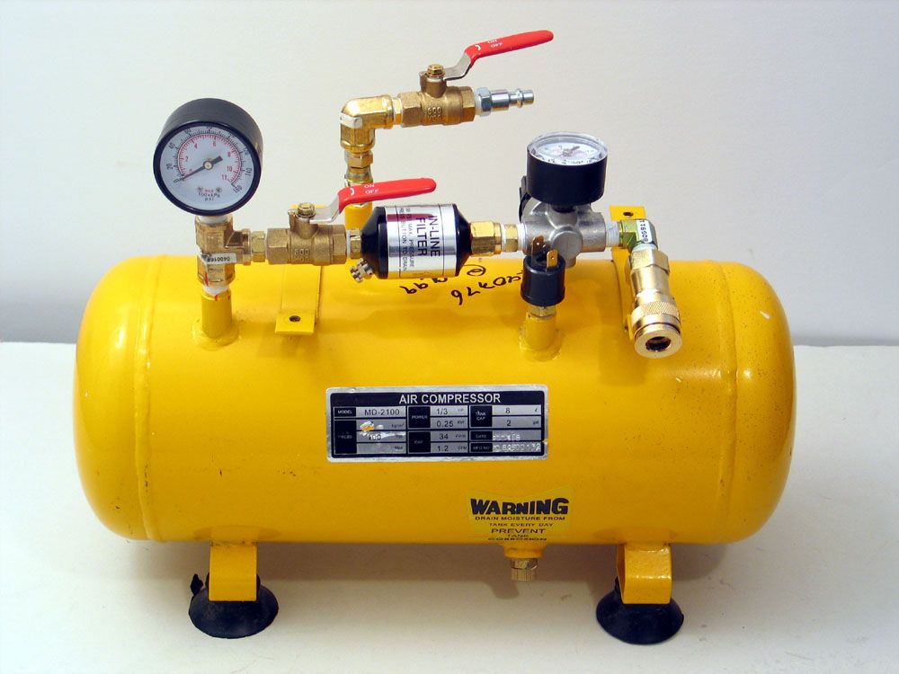 Figure 10 – Air supply tank |
As mentioned, virtually any air source will power the T-locker, from bicycle pump to CO2 tank. The best setup is to have some sort of small storage tank, which can be filled as required from whatever air source you have. I scrounged around the local surplus store and found a small 2-gallon tank that was originally connected to a small portable compressor (Figure 10). For some reason I decided to make it resemble a small nuclear reactor! In fact, each component has a function. In the background you can see the fill port with quick-disconnect and manual valve. This allows me to fill my tank from virtually any source – my engine-mounted OBA compressor, my CO2 tank, or a cheap plug-in electric compressor. I can even fill the tank directly from my shop compressor and it will hold enough air for a full days locking and unlocking. On the outlet side, from left to right, I have the tank pressure gauge, shutoff valve, filter, regulator with gauge, and a universal air-tool quick-connect fitting that connects to the supply line running to the T-locker switch. It’s important to supply the cylinder with clean, dry air and I have found that 80 psi is about optimum. | ||||
Protecting the Cylinder |
|||||
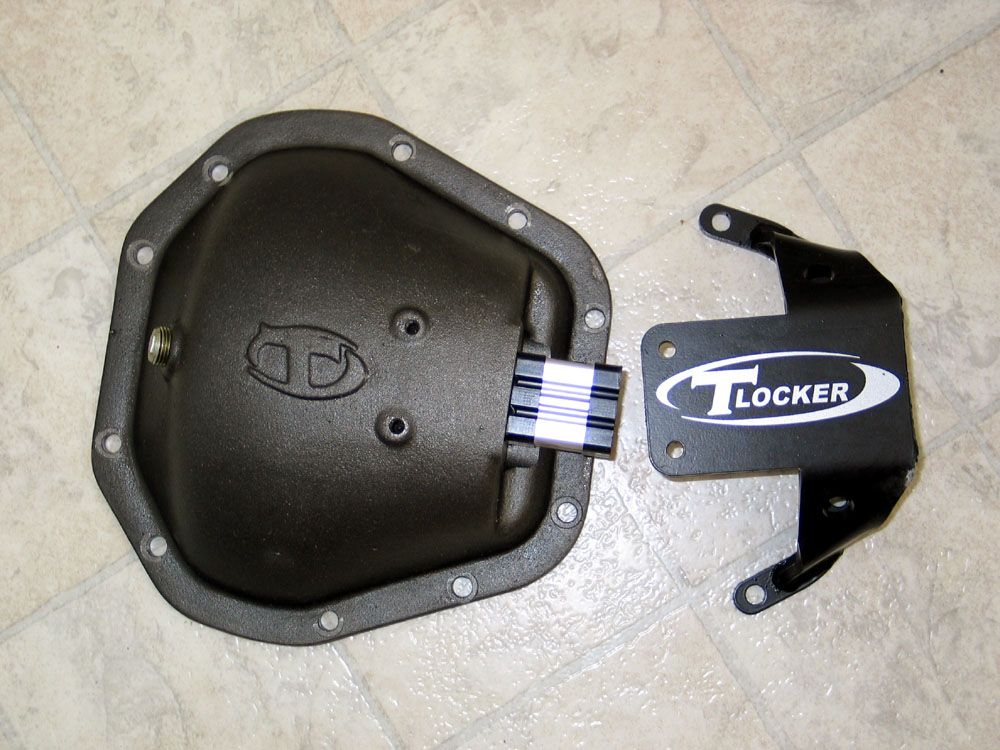
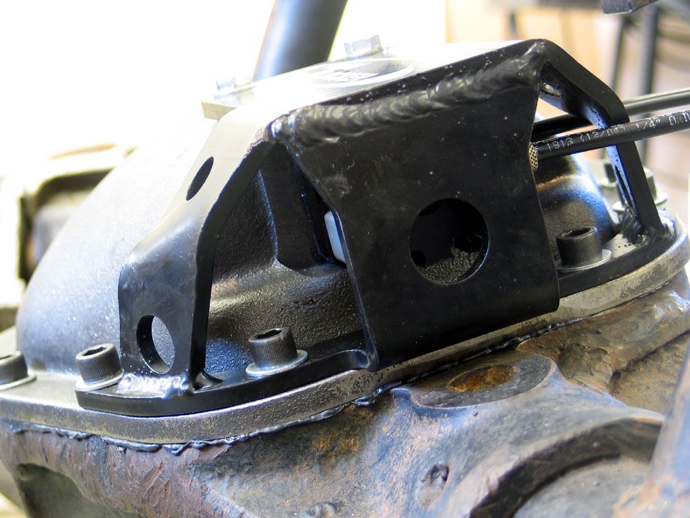 Figure 11 – Quarter-inch steel cylinder guard |
The only possible drawback to the externally-shifted design of the T-locker is that the pneumatic cylinder must be protected – but this is easily done. To begin with, the cylinder is very compact and securely mounted to the diff cover (Figure 6). The T-locker also comes with a stout, compact, quarter-inch steel guard that fits closely over the cylinder, keeping it well protected without resulting in any overhang or loss of clearance (Figures 11 and 12). The cylinder-guard bolts to the housing with four 3/8” socket-head cap screws and to the massive 5/16” cast steel diff cover with two additional hex-head bolts. | ||||
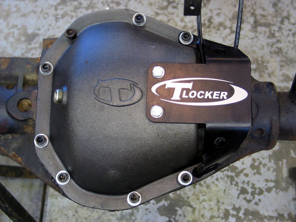 Figure 12 – Installed T-locker with cylinder guard and air-lines in place |
Even for those of us, like me, who prefer to “drive by brail” in the rocks, there should be no concerns with damaging the cylinder. If, however, the worst should happen, replacement parts are available from Teraflex. | ||||
InstallationEssentially, installation involves assembling the air cylinder to the diff cover, installing the locker and setting-up the gears, adjusting the shift fork position, bolting on the diff cover, installing the air lines, and installing the cylinder guard. The installation instructions provided with the T-locker are actually pretty good so I’ll just mention the following tips and info I learned along the way.Installing the locker in the housing is the same as installing any carrier, the only exception being that prior to installing the carrier bearings you must first remove the zip-tie that holds the shift collar and locking-pins in place during shipment. Once you have removed it, be careful not to hold the locker in such a way that the set-up bearing can slide off, allowing the shift collar and locking-pins to fall out and scatter all over the floor. (Ask me how I figured this out!) Once the locker is installed and the gears set-up, the only tricky part of the installation is adjusting the shift fork position so that its throw is both sufficient and in the right location to completely lock and unlock the locker when the cylinder is actuated. I used the following method to accomplish this: |
|||||
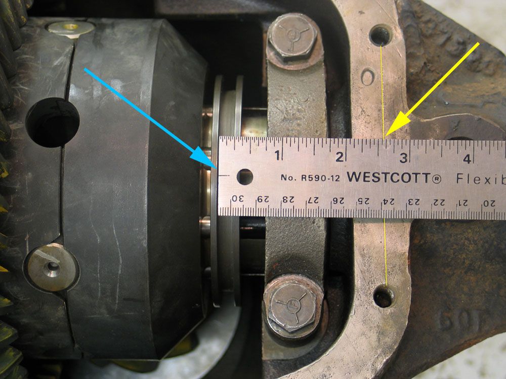 Figure 13 – measuring “lock position” of shift collar |
1. Referring to Figure 13: Slide the locking collar all the way towards the centre of the diff, and ensure the locker is fully locked. Scribe a line between the centres of the two cover-bolt holes on the housing (yellow arrow). Measure the distance from the inside of the inner lip on the shift collar (blue arrow) to the line you just scribed – this is the “lock position” of the shift fork. | ||||
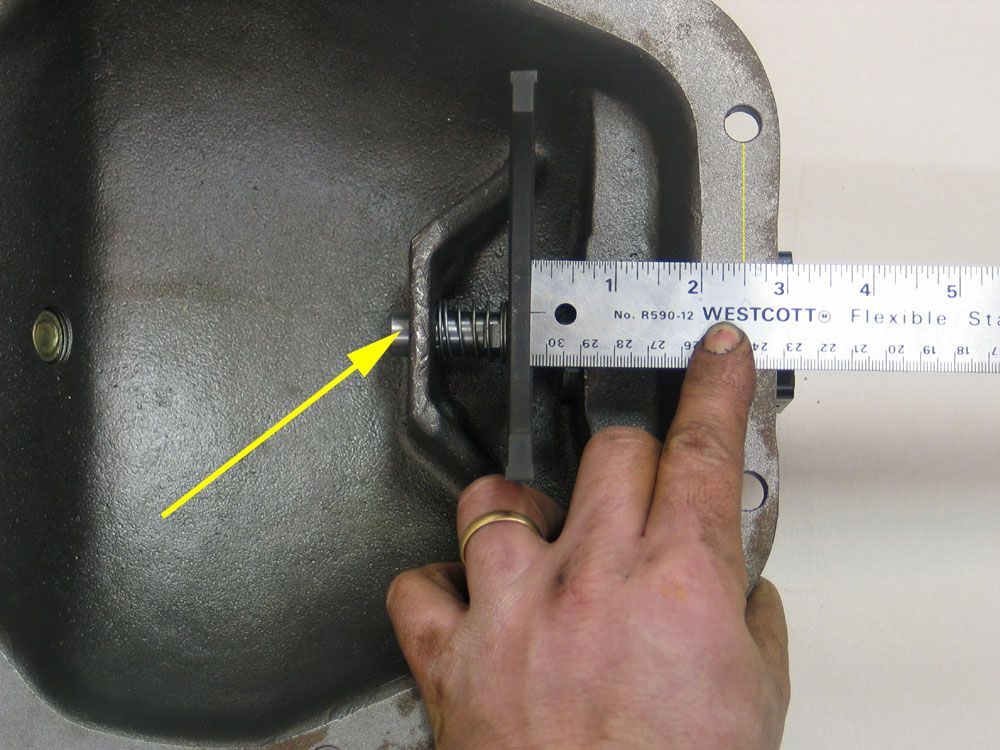 Figure 14 – measuring “lock position” of shift fork |
2. Referring to Figure
14: Scribe a vertical line between the centres of the corresponding bolt
holes on the diff cover. Move the shift fork to the centre, locked position
and holding it in place, measure the distance from the outside edge of the
shift fork to the scribed line. This measurement should be the same as that
obtained in step 1. If it is not, adjust the position of the shift fork
on the cylinder rod by screwing the shift shaft (yellow arrow) and jam nut
in or out, until the measurements are equal. 3. Move the shift fork from locked to unlocked and using the scribe line on the diff cover as a reference, measure the total throw of the shift fork from the locked to unlocked positions; the “fork throw”. 4. Returning to the axle housing, and measuring from the scribed line, slide the shift collar away from the centre a distance equal to the “fork throw” measured in step 3, making sure that the locker completely unlocks. 5. With the locker unlocked and measuring from the scribe line again, make a note of the shift collar’s “unlocked position”. |
||||
| 6. Double-check the shift fork position as follows: On the diff cover, allow
the spring to return the shift fork to the unlocked position, then measure
from the shift fork to the scribed line as in step 2, confirming the shift
fork’s unlocked position is the same as that for the shift collar. 7. Repeat steps 1-6 until the measurements for the lock and unlock position of the shift collar are equal to the measurements for the lock and unlock position of the shift fork. |
|||||
When plumbing the system, the following tips will help:• Tighten the air-line
fittings into the switch or the cylinder before attaching the air line to the
fitting. For ImprovementNothing’s ever really perfect, there are always things that can be better, and I’m committed to always pointing out what I think needs improvement – both as information for you, the reader and potential customer, and also for the company concerned, should they wish to act on any of my suggestions. With that said, the T-locker made this part of my job pretty difficult – there really isn’t a whole lot that can be improved as far as I can tell, so I’m really digging here: • The mounting holes
on the diff cover are drilled slightly oversize, presumably to facilitate installing
the diff cover, getting the bolts all lined up, and getting the shift fork engaged
in the locking collar all at one time. Fair enough - but this necessitates the
use of washers under the heads of the supplied cover bolts. Sadly, the supplied
washers are cheap junk, far too soft for the job. When you tighten the bolts
anywhere near the Dana recommended 40 ft lbs the washers squish and splay out,
becoming useless and endangering proper cover-to-housing clamping load. Throw
them out and use some decent hardened washers, such as SAE Grade 8. |
|||||
|
|||||
|
Sources: TERAFLEX Tibus
Offroad |
|