 |
JMR MB1000 Manual Tube Bender By Bill "BillaVista" Ansell |
IntroductionIn my last article on tube notching, I wrote:
|
 |
||
Of course, notching tube is only one half of the battle - to become the fabricator you have always wanted to be you have to enter the realm of the tube benders! However, when taking the leap into a whole new realm of fabrication it's important to both choose quality tools and to learn how to use them. The aim of this article is to introduce you to the JMR MB1000 manual tube bender and demonstrate how it works and how to use it. There's even video!. Unlike the tube notcher, which, although it has many not-so-obvious features, has a fairly intuitive basic operation, a tube bender is not quite so simplistic. In fact, as a wise man once brilliantly said:
Rob made that quote at the opening of his now-classic article on tube bending, "Bendin' Tube 101", which he wrote almost a decade ago! It is a testament to how great that article is that it has stood the test of time so well. In it, Rob provides simple instructions born of experience for laying out and creating designs from bent tube. I shall not attempt to duplicate this at all - not only is it unnecessary, but I would only embarrass myself as his skill far exceeds mine in this department. Rather, what I'm going to do is back up and take you right from the point where you're sitting in front of your computer surfing the internet and scratching your head wondering what bender to buy up to where you can comfortably bend tube in your bender and follow Rob's instructions. So, here we are going to cover: Assembly and Mounting of the JMR MB1000 |
|||
Nomenclature & OperationOK, so we're faced with a bit of a chicken-and-the-egg situation here. Either I explain how the bender works, using terms with which you may be unfamiliar, or I show you the parts and their names first, which may be confusing if you don't know how the parts work! Let's see if we can juggle this and make it all crystal-clear! (of course, you my wish to jump ahead to the end and watch the Instructional Video first, as it may help you visualize things through the remainder of the article) |
|||
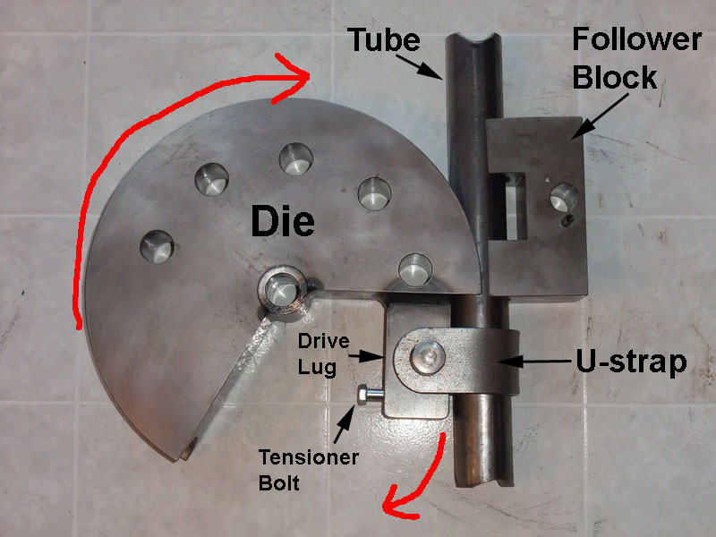 |
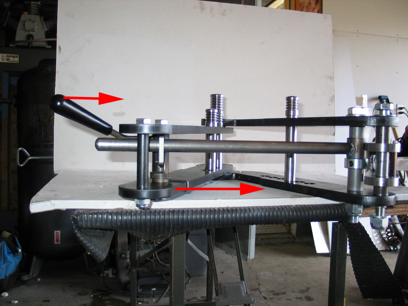
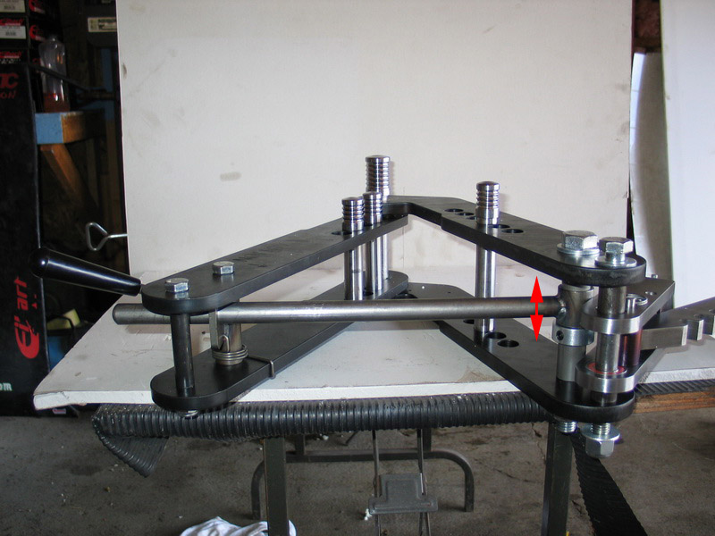
How the tube gets bent.The JMR MB1000 is what is known as a "rotary draw bender". Basically, a rotary draw bender works by drawing the tube through a die-and-follower-block as the die is rotated - hence the name! The die and follower-block are just large, heavy chunks of specially-shaped steel. Using the picture at left, imagine the die and follower-block were held rigidly in position, but the die was free to rotate. Now imagine that the die were to be rotated in the direction of the red arrows. You should be able to envision that, as the die rotates, the tube (held securely to the die by the U-strap and tensioner bolt) is drawn between the die and follower-block. As the tube rotates with the die, the follower-block prevents the tube from swinging out, and forces the tube to bend as the die rotates. |
||||||||||||||||||||||||||||||||||||||||||||||||||||||||||||||||||||||||||||||||||||||||||||||||||||||||||||||||||||||||||||||||||||||||||||||||||||||||||||||||||||||||||||||||||||||||||||||||||||||||||||||||||||||||||||||||||||||||||||||||||||||||||||||||||||||||||||||||||||||||||||||||||||||||||||||||||||||||||||||||||||||||||||
That's really all there is to it. The die rotates, the tube is trapped between the die and the follower-block, and so the tube rotates with the die and in doing so, the tube gets bent. Of course, this doesn't happen by magic, the tube-bending machine must support the die and follower and must provide the means for rotating the die. Before we examine exactly how it does that, let's go over some of the part names. |
|||||||||||||||||||||||||||||||||||||||||||||||||||||||||||||||||||||||||||||||||||||||||||||||||||||||||||||||||||||||||||||||||||||||||||||||||||||||||||||||||||||||||||||||||||||||||||||||||||||||||||||||||||||||||||||||||||||||||||||||||||||||||||||||||||||||||||||||||||||||||||||||||||||||||||||||||||||||||||||||||||||||||||||
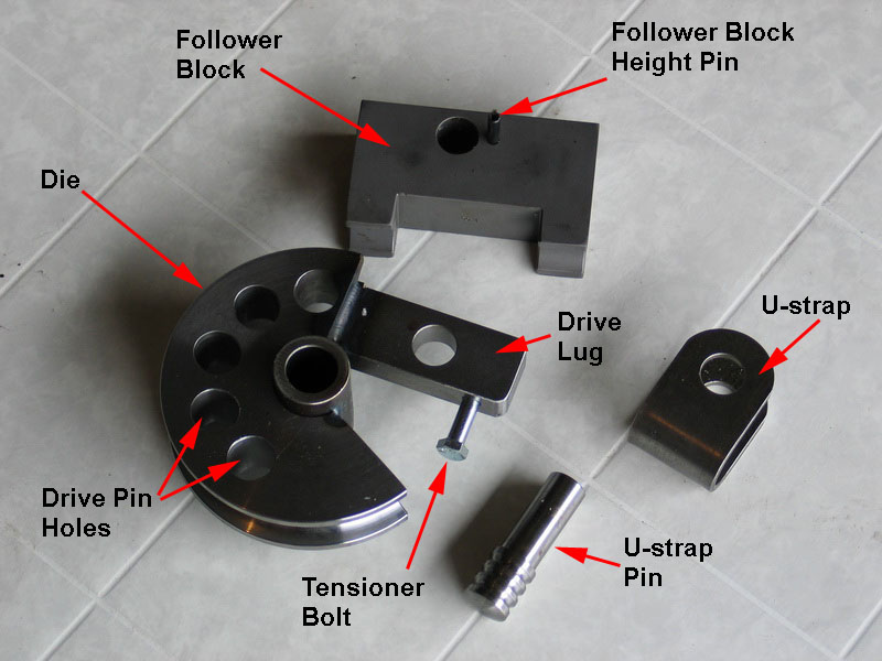 |
This is a die and follower-block set. Die's come in different specific sizes for bending a single size of tube (more on this later) and each must have a matching follower-block and U-strap. The picture at left is of a JMR die for 1" tubing. |
||||||||||||||||||||||||||||||||||||||||||||||||||||||||||||||||||||||||||||||||||||||||||||||||||||||||||||||||||||||||||||||||||||||||||||||||||||||||||||||||||||||||||||||||||||||||||||||||||||||||||||||||||||||||||||||||||||||||||||||||||||||||||||||||||||||||||||||||||||||||||||||||||||||||||||||||||||||||||||||||||||||||||||
 |
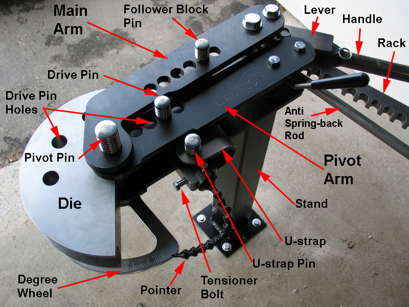
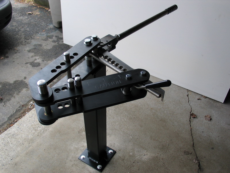
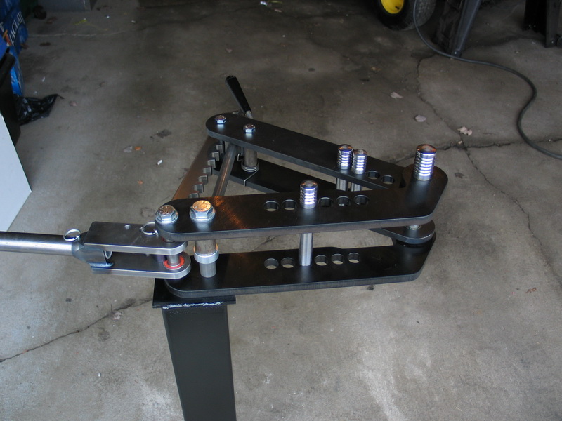
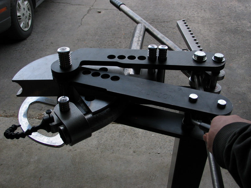
These are the main components of the tube bender itself. The main arms are held fixed, the handle is inserted in the lever, and together they operate the drive rack which opens the pivot arms in relation to the main arms. It is this action of opening the pivot arms that rotates the die that bends the tube. |
||||||||||||||||||||||||||||||||||||||||||||||||||||||||||||||||||||||||||||||||||||||||||||||||||||||||||||||||||||||||||||||||||||||||||||||||||||||||||||||||||||||||||||||||||||||||||||||||||||||||||||||||||||||||||||||||||||||||||||||||||||||||||||||||||||||||||||||||||||||||||||||||||||||||||||||||||||||||||||||||||||||||||||
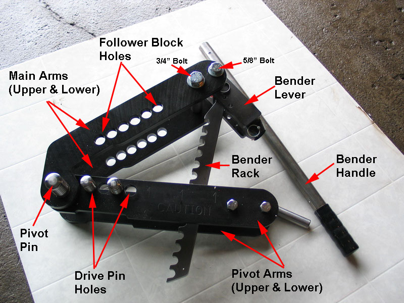 |
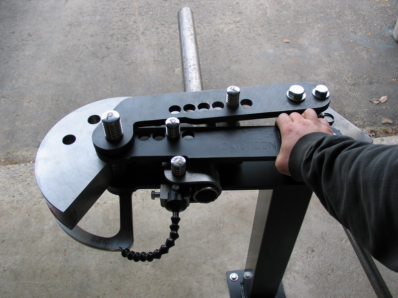
Basically, the main arms get fixed to a stand, and the pivot arms are ratcheted away from the main arms by the rack as the user pulls the handle attached to the lever. As the pivot arms "open up" in relation to the main arms, the die is rotated and the tube is bent. |
||||||||||||||||||||||||||||||||||||||||||||||||||||||||||||||||||||||||||||||||||||||||||||||||||||||||||||||||||||||||||||||||||||||||||||||||||||||||||||||||||||||||||||||||||||||||||||||||||||||||||||||||||||||||||||||||||||||||||||||||||||||||||||||||||||||||||||||||||||||||||||||||||||||||||||||||||||||||||||||||||||||||||||
 |
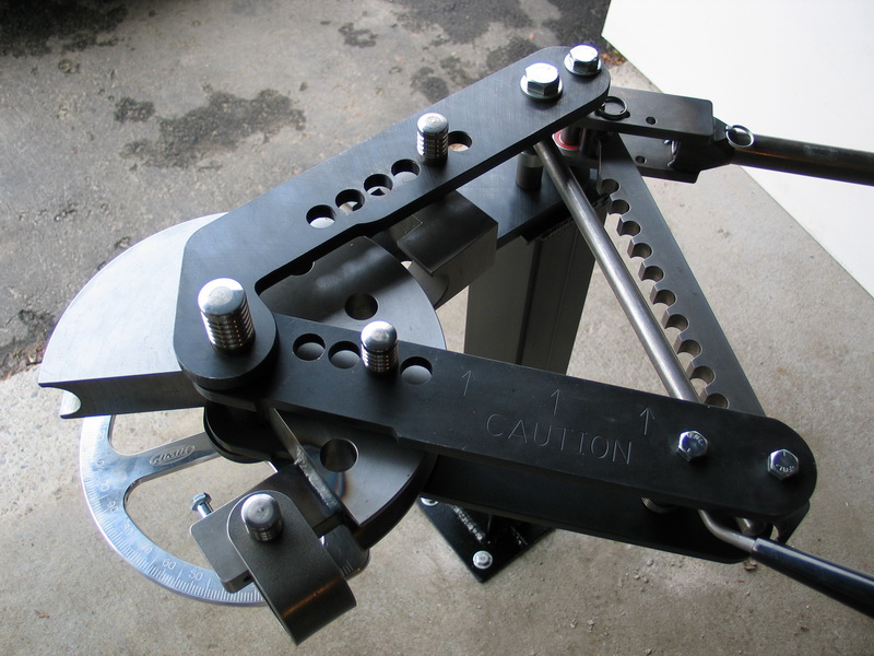
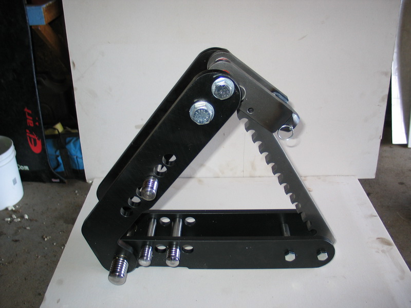
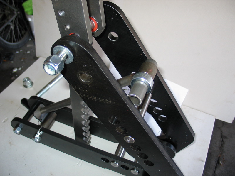
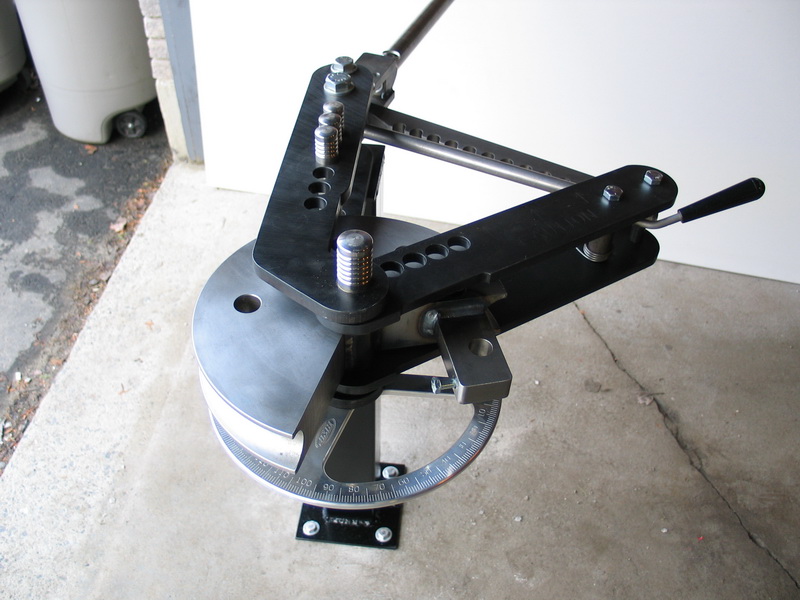
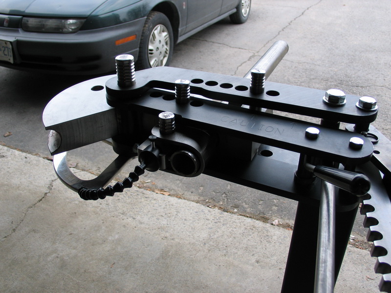
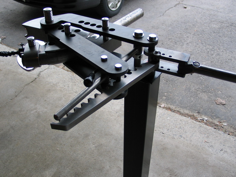
This shows the whole assembly all together in the "closed" position. | ||||||||||||||||||||||||||||||||||||||||||||||||||||||||||||||||||||||||||||||||||||||||||||||||||||||||||||||||||||||||||||||||||||||||||||||||||||||||||||||||||||||||||||||||||||||||||||||||||||||||||||||||||||||||||||||||||||||||||||||||||||||||||||||||||||||||||||||||||||||||||||||||||||||||||||||||||||||||||||||||||||||||||||
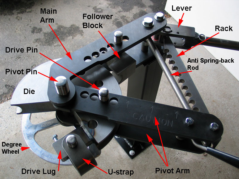 |
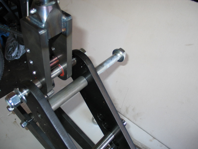
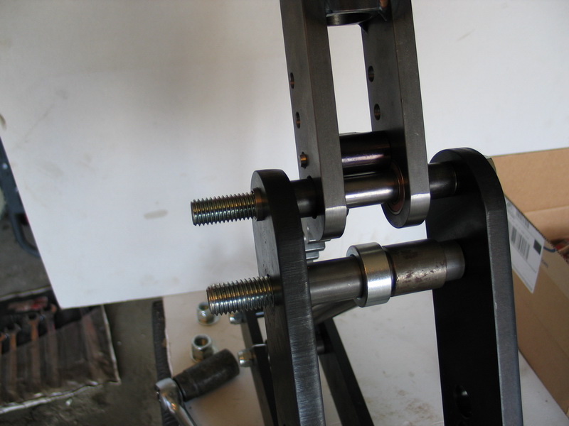
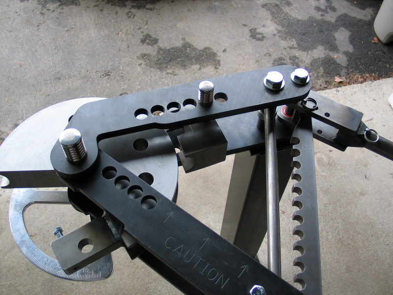
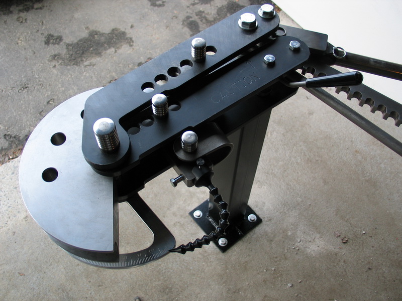
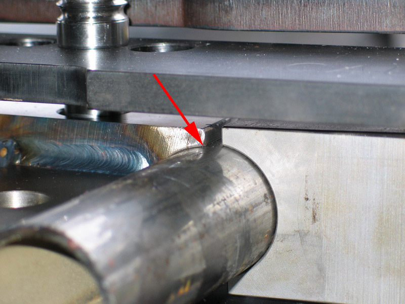
This is the whole assembly in the "open" position, as it would be if the tube was being bent. Note that the pivot arms and die both rotate about the pivot pin, and that the drive pin is what locks the pivot arms and die together, so that when the pivot arms are "opened" by means of the rack, the die rotates and the tube is bent around the die, held in place by the follower-block.
|
||||||||||||||||||||||||||||||||||||||||||||||||||||||||||||||||||||||||||||||||||||||||||||||||||||||||||||||||||||||||||||||||||||||||||||||||||||||||||||||||||||||||||||||||||||||||||||||||||||||||||||||||||||||||||||||||||||||||||||||||||||||||||||||||||||||||||||||||||||||||||||||||||||||||||||||||||||||||||||||||||||||||||||
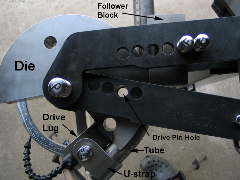 |
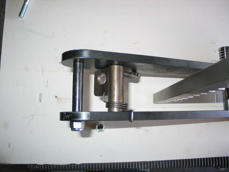
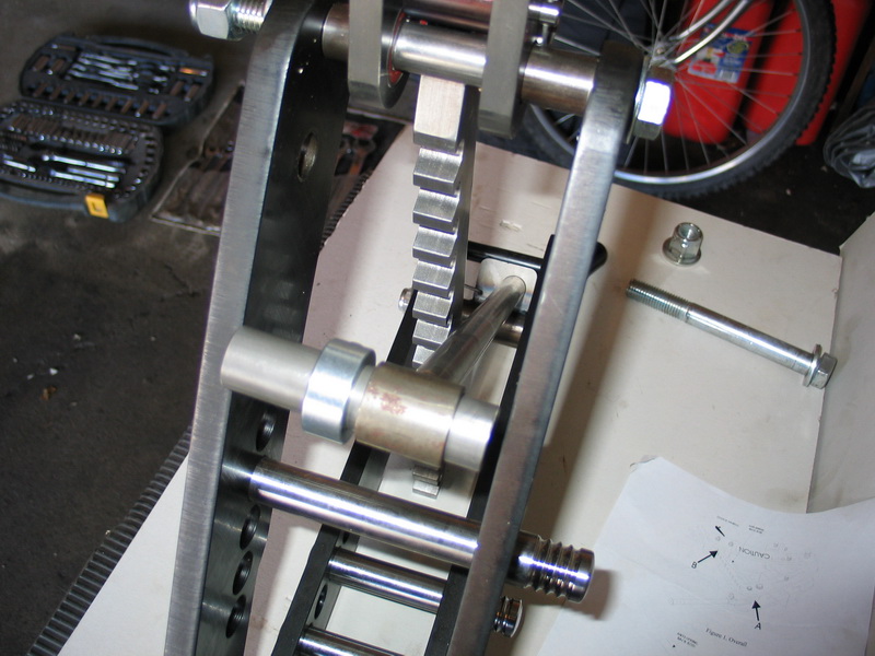
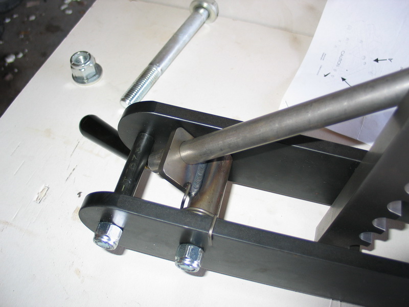
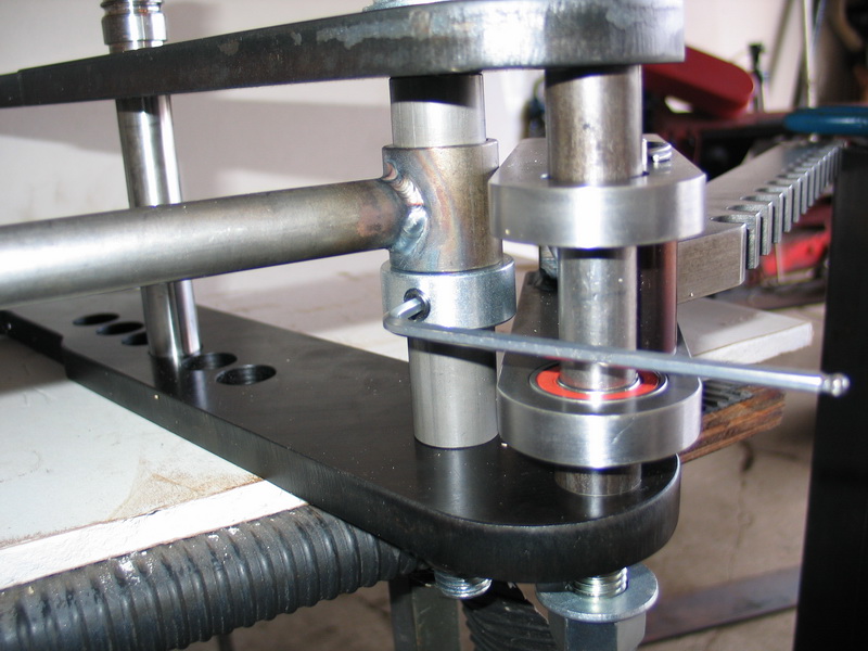
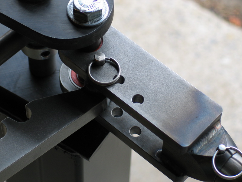
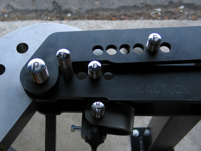
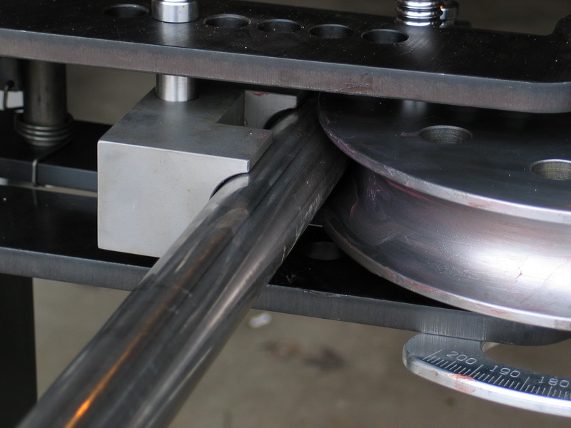
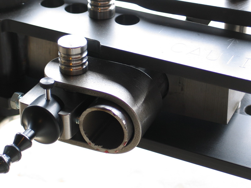
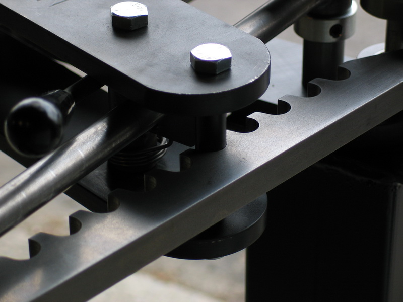
Here's a close-up of the bender with a tube in the process of being bent. Note how the tube is held against the die by the U-strap, is prevented from swinging out by the follower-block, and is therefore forced to rotate with the die and get bent. Note also that in this pic I have removed the drive pin from the drive pin hole so you can see how, when inserted, the drive pin pins the pivot arms and die together. In this pic, the drive pin has been temporarily set in an open follower-block pin hole, right next to the follower-block pin (which is holding the follower-block in place). |
||||||||||||||||||||||||||||||||||||||||||||||||||||||||||||||||||||||||||||||||||||||||||||||||||||||||||||||||||||||||||||||||||||||||||||||||||||||||||||||||||||||||||||||||||||||||||||||||||||||||||||||||||||||||||||||||||||||||||||||||||||||||||||||||||||||||||||||||||||||||||||||||||||||||||||||||||||||||||||||||||||||||||||
Yes, there are quite a few pins to keep track of - which is why I labelled them with my trusty Sharpie marker. In the above pic:
The following short video clip illustrates the action of the user pulling the handle to successively engage the teeth of the rack and force "open" the pivot arms, thereby rotating the die and bending the tube. For ease of illustration, there is no tube installed in the machine in this clip. Note that one full "sweep" of the entire rack rotates the die (and therefore bends the tube) about 55°. Since there are 14 teeth on the rack, that means each tooth (or in other words, each full pull on the handle,) rotates the die and bends the tube approximately 4°.
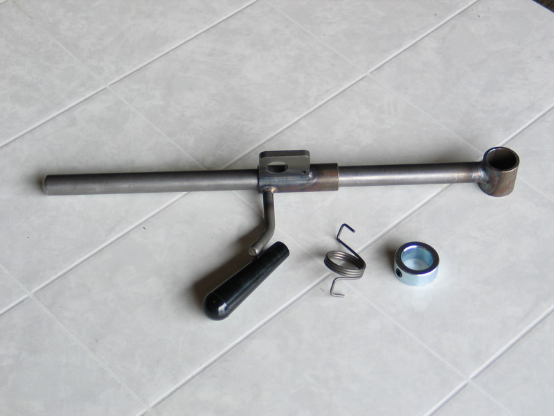
Assembly and Mounting of the JMR MB1000OK,so now we have at least a passing idea of what the parts are called and how the machine operates, let`s have a detailed look at the assembly of the machine, including installing the optional degree ring and anti-spring-back kit, before moving on to the features and benefits of the JMR bender and closing with some instruction on actually using the bender. Components |
|||||||||||||||||||||||||||||||||||||||||||||||||||||||||||||||||||||||||||||||||||||||||||||||||||||||||||||||||||||||||||||||||||||||||||||||||||||||||||||||||||||||||||||||||||||||||||||||||||||||||||||||||||||||||||||||||||||||||||||||||||||||||||||||||||||||||||||||||||||||||||||||||||||||||||||||||||||||||||||||||||||||||||||
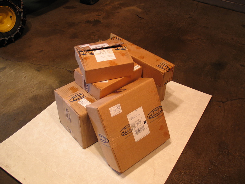 |
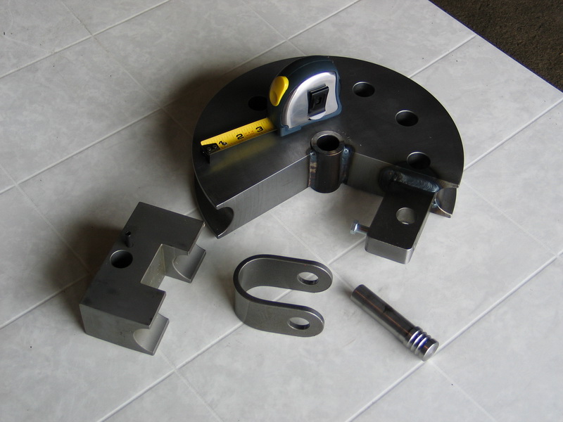
I ordered the following components:
|
||||||||||||||||||||||||||||||||||||||||||||||||||||||||||||||||||||||||||||||||||||||||||||||||||||||||||||||||||||||||||||||||||||||||||||||||||||||||||||||||||||||||||||||||||||||||||||||||||||||||||||||||||||||||||||||||||||||||||||||||||||||||||||||||||||||||||||||||||||||||||||||||||||||||||||||||||||||||||||||||||||||||||||
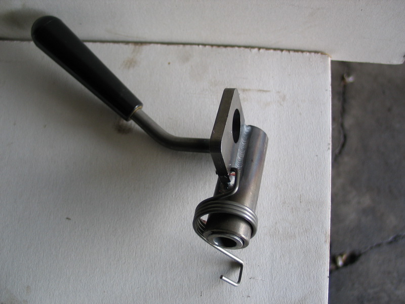
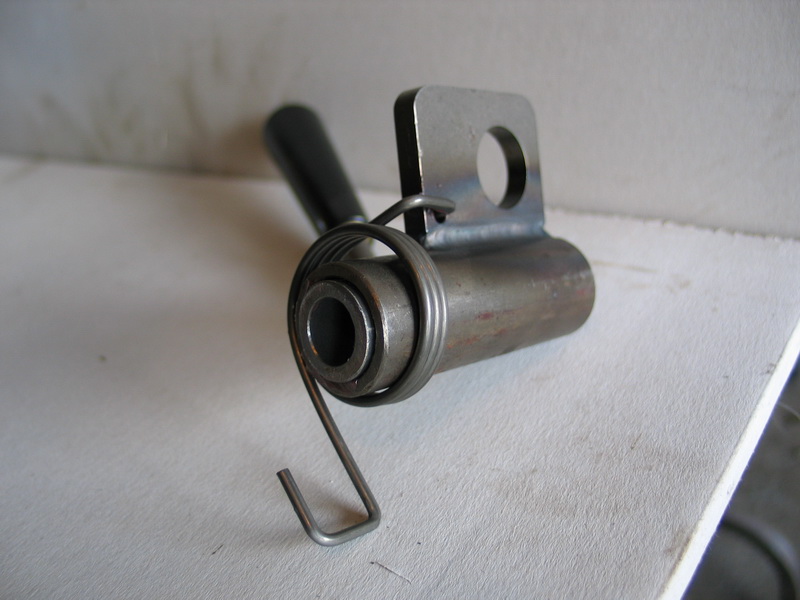
Anti-spring-back kit |
|||||||||||||||||||||||||||||||||||||||||||||||||||||||||||||||||||||||||||||||||||||||||||||||||||||||||||||||||||||||||||||||||||||||||||||||||||||||||||||||||||||||||||||||||||||||||||||||||||||||||||||||||||||||||||||||||||||||||||||||||||||||||||||||||||||||||||||||||||||||||||||||||||||||||||||||||||||||||||||||||||||||||||||
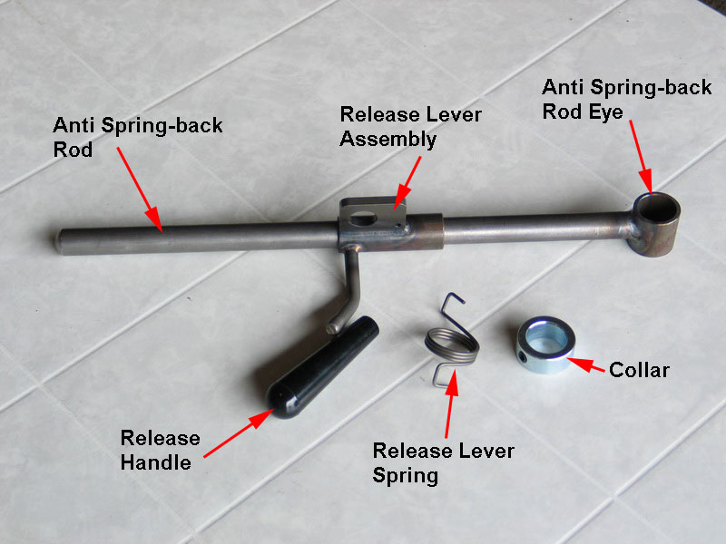 |
The ASN100 Anti-spring-back kit is an optional accessory that you can install on your bender to prevent tube spring-back as you bend. All steel tubing has a tendency to want to return to its original size and shape. This means that, as you bend tube, it will "spring back" a little so that the actual bend that you achieve will be a few degrees less than indicated during the bending process. Without an anti-spring-back kit, this means that every time you pull on the handle and then relax the handle to engage the next tooth on the drive rack, the tube will spring back a small amount. This makes it challenging to achieve quick, smooth, accurate bends to a specified number of degrees. |
||||||||||||||||||||||||||||||||||||||||||||||||||||||||||||||||||||||||||||||||||||||||||||||||||||||||||||||||||||||||||||||||||||||||||||||||||||||||||||||||||||||||||||||||||||||||||||||||||||||||||||||||||||||||||||||||||||||||||||||||||||||||||||||||||||||||||||||||||||||||||||||||||||||||||||||||||||||||||||||||||||||||||||
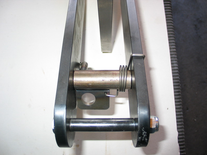
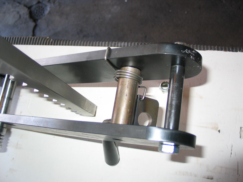
The anti-spring-back kit is installed to act as something of a one-way clutch, so that while the bender is in operation and the bend is being made, the tube cannot spring back as the operator goes from tooth-to-tooth on the rack. Note, however, that this WILL NOT prevent the tube from springing back a small amount when the bend is finished and the tube is removed from the machine. Nothing can prevent this, it is a property of the material being bent. The only solution for this is to calculate, for each size and material being bent, how much the final spring-back is, and compensate by over-bending the tube that may degrees before removing the tube from the machine. For example, suppose that through trial we discover that bending a particular brand of 1.75" .120 wall HREW tubing to 90° results in 6° of spring back (i.e. that if we bend the tube to exactly 90° and remove it from the bender, we find that it springs back 6° and the final finished bend will actually only be 84°). If we wish to bend an exact 90° bend, we simply bend the tube to 90° + 6° = 96°. That way, when removed, the tube springs back about 6° and we are left with a perfect 90° bend. What the anti-spring-back kit DOES do, is prevent the spring-back while operator works his/her way down the rack, which in turn makes it very simple to easily follow the degree ring and see the angle of the bend as it is being made. This makes the whole operation easier, smoother, more accurate, and more repeatable. The device is very simple in operation: as the pivot arms open, the release lever assembly binds on the anti-spring-back rod which prevents the pivot arms from being able to close while still allowing them to open smoothly with no hindrance. When the operator wishes to return the pivot arms to the closed position, either to re-set the rack and continue bending or to remove the tube on completion of the bend, he can do so by pushing the release handle which forces the release lever assembly back against the release lever spring and allows the rod to pass through the release lever assembly and therefore the pivot arms to close. The anti-spring-back kit is particularly useful when bending certain materials, such as 4130 chrome-moly alloy steel and stainless steel, as these materials exhibit a high-degree of spring-back and bending them without an anti-spring-back kit can be an exercise in frustration. Another great advantage to using the anti-spring-back kit, regardless of the material being bent, is that because it prevents spring-back, it means that the operator can pause during the bending operation to check the degree of bend indicated on the degree ring, without having to hold tension on the handle. This makes small, precise adjustments a snap. This short video clip illustrates the anti-spring-back kit in operation:
Dies |
|||||||||||||||||||||||||||||||||||||||||||||||||||||||||||||||||||||||||||||||||||||||||||||||||||||||||||||||||||||||||||||||||||||||||||||||||||||||||||||||||||||||||||||||||||||||||||||||||||||||||||||||||||||||||||||||||||||||||||||||||||||||||||||||||||||||||||||||||||||||||||||||||||||||||||||||||||||||||||||||||||||||||||||
 |
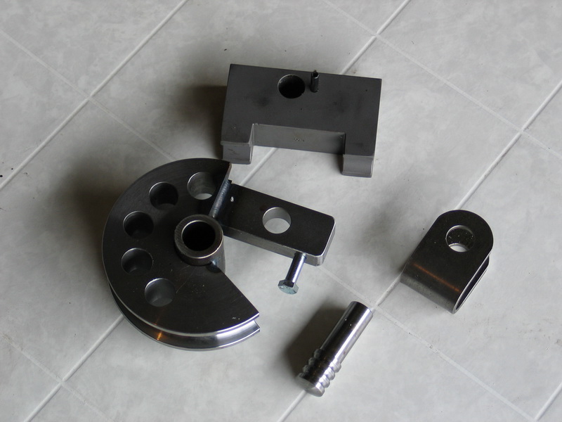
This is the 1.75" die set. Each die set consists of:
The shear size and weight of these dies is a fairly awesome thing. |
||||||||||||||||||||||||||||||||||||||||||||||||||||||||||||||||||||||||||||||||||||||||||||||||||||||||||||||||||||||||||||||||||||||||||||||||||||||||||||||||||||||||||||||||||||||||||||||||||||||||||||||||||||||||||||||||||||||||||||||||||||||||||||||||||||||||||||||||||||||||||||||||||||||||||||||||||||||||||||||||||||||||||||
 |
This is the 1" tube die set. We'll cover the details of die specs, like CLR, and how to choose dies, later in the article. Both of my dies are 240° dies, both for round tubing, and the 1.75" has a 6" CLR, while the 1" has a 3" CLR |
||||||||||||||||||||||||||||||||||||||||||||||||||||||||||||||||||||||||||||||||||||||||||||||||||||||||||||||||||||||||||||||||||||||||||||||||||||||||||||||||||||||||||||||||||||||||||||||||||||||||||||||||||||||||||||||||||||||||||||||||||||||||||||||||||||||||||||||||||||||||||||||||||||||||||||||||||||||||||||||||||||||||||||
Degree ring |
|||||||||||||||||||||||||||||||||||||||||||||||||||||||||||||||||||||||||||||||||||||||||||||||||||||||||||||||||||||||||||||||||||||||||||||||||||||||||||||||||||||||||||||||||||||||||||||||||||||||||||||||||||||||||||||||||||||||||||||||||||||||||||||||||||||||||||||||||||||||||||||||||||||||||||||||||||||||||||||||||||||||||||||
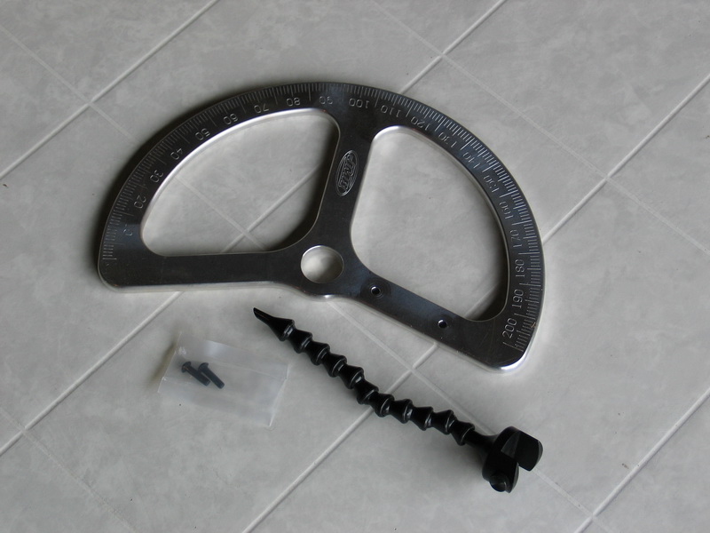 |
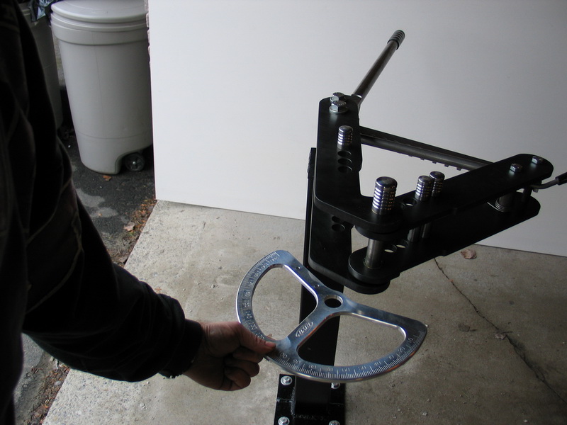
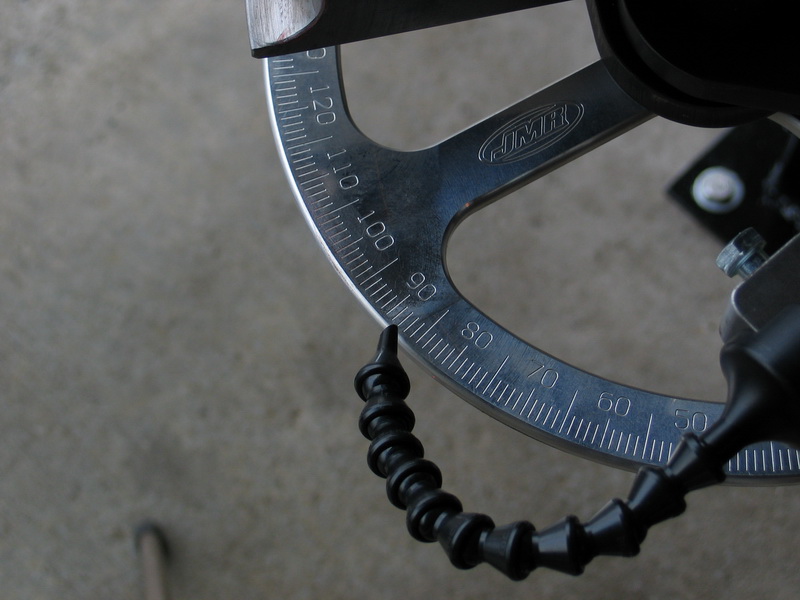
This is the "optional" degree ring for the JMR bender. It is part number DGW100, and includes the machined aluminum degree ring, the flexible pointer, and two mounting screws. I say "optional" in quotes because, although the kit is an optional extra that you need to order, I can't imagine having a bender without one. |
||||||||||||||||||||||||||||||||||||||||||||||||||||||||||||||||||||||||||||||||||||||||||||||||||||||||||||||||||||||||||||||||||||||||||||||||||||||||||||||||||||||||||||||||||||||||||||||||||||||||||||||||||||||||||||||||||||||||||||||||||||||||||||||||||||||||||||||||||||||||||||||||||||||||||||||||||||||||||||||||||||||||||||
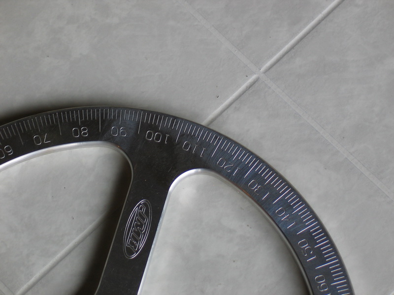 |
The JMR degree ring is rugged, accurate, and very easy to read - even during bending. |
||||||||||||||||||||||||||||||||||||||||||||||||||||||||||||||||||||||||||||||||||||||||||||||||||||||||||||||||||||||||||||||||||||||||||||||||||||||||||||||||||||||||||||||||||||||||||||||||||||||||||||||||||||||||||||||||||||||||||||||||||||||||||||||||||||||||||||||||||||||||||||||||||||||||||||||||||||||||||||||||||||||||||||
Bender |
|||||||||||||||||||||||||||||||||||||||||||||||||||||||||||||||||||||||||||||||||||||||||||||||||||||||||||||||||||||||||||||||||||||||||||||||||||||||||||||||||||||||||||||||||||||||||||||||||||||||||||||||||||||||||||||||||||||||||||||||||||||||||||||||||||||||||||||||||||||||||||||||||||||||||||||||||||||||||||||||||||||||||||||
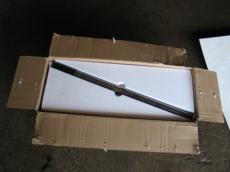 |
And finally, this is the bender itself: with the included rubber-gripped handle packed separately on top... |
||||||||||||||||||||||||||||||||||||||||||||||||||||||||||||||||||||||||||||||||||||||||||||||||||||||||||||||||||||||||||||||||||||||||||||||||||||||||||||||||||||||||||||||||||||||||||||||||||||||||||||||||||||||||||||||||||||||||||||||||||||||||||||||||||||||||||||||||||||||||||||||||||||||||||||||||||||||||||||||||||||||||||||
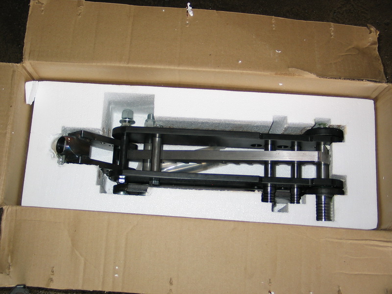 |
... and the bender packed below. | ||||||||||||||||||||||||||||||||||||||||||||||||||||||||||||||||||||||||||||||||||||||||||||||||||||||||||||||||||||||||||||||||||||||||||||||||||||||||||||||||||||||||||||||||||||||||||||||||||||||||||||||||||||||||||||||||||||||||||||||||||||||||||||||||||||||||||||||||||||||||||||||||||||||||||||||||||||||||||||||||||||||||||||
 |
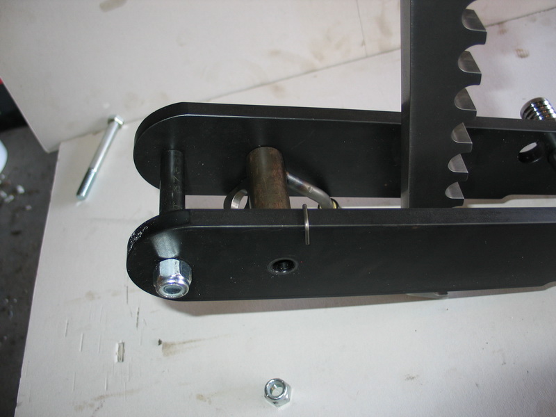
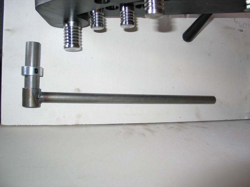
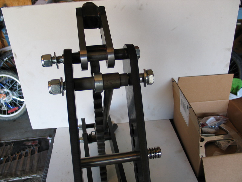
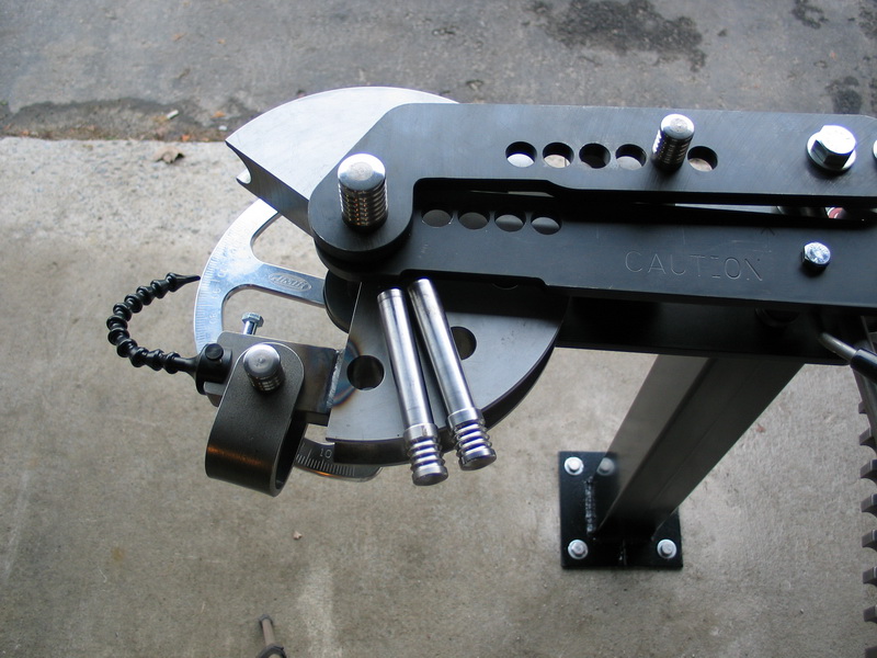
The bender ships with all the pins, all of which are precision-machined, heat treated 4140 chrome-moly alloy steel. There is a pivot pin, follower-block pin, and two drive pins - one for larger dies (like the 1.75" tube die) and one for smaller dies (like the 1.0" tube die). In this pic, the pivot pin and follower-block pins are both installed, and the two drive pins are each in a different drive hole in the pivot arms. |
||||||||||||||||||||||||||||||||||||||||||||||||||||||||||||||||||||||||||||||||||||||||||||||||||||||||||||||||||||||||||||||||||||||||||||||||||||||||||||||||||||||||||||||||||||||||||||||||||||||||||||||||||||||||||||||||||||||||||||||||||||||||||||||||||||||||||||||||||||||||||||||||||||||||||||||||||||||||||||||||||||||||||||
Installing the Anti-Spring-Back Kit.
OK, so before we bolt this thing to some large immovable object and start kinking tube with it, first we're going to install the anti-spring-back kit and the degree ring - neither of which are really optional in my humble opinion - I highly recommend that you order, install, and use both. As a side note, the JMR anti-spring-back kit can be installed and will also work on other brands of benders. |
|||||||||||||||||||||||||||||||||||||||||||||||||||||||||||||||||||||||||||||||||||||||||||||||||||||||||||||||||||||||||||||||||||||||||||||||||||||||||||||||||||||||||||||||||||||||||||||||||||||||||||||||||||||||||||||||||||||||||||||||||||||||||||||||||||||||||||||||||||||||||||||||||||||||||||||||||||||||||||||||||||||||||||||
 |
Remove the nut and bolt from the innermost position on the pivot arms. | ||||||||||||||||||||||||||||||||||||||||||||||||||||||||||||||||||||||||||||||||||||||||||||||||||||||||||||||||||||||||||||||||||||||||||||||||||||||||||||||||||||||||||||||||||||||||||||||||||||||||||||||||||||||||||||||||||||||||||||||||||||||||||||||||||||||||||||||||||||||||||||||||||||||||||||||||||||||||||||||||||||||||||||
 |
Remove the sleeve between the two pivot arms. | ||||||||||||||||||||||||||||||||||||||||||||||||||||||||||||||||||||||||||||||||||||||||||||||||||||||||||||||||||||||||||||||||||||||||||||||||||||||||||||||||||||||||||||||||||||||||||||||||||||||||||||||||||||||||||||||||||||||||||||||||||||||||||||||||||||||||||||||||||||||||||||||||||||||||||||||||||||||||||||||||||||||||||||
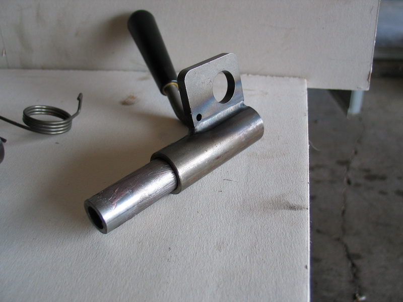 |
Lightly grease the removed sleeve and slide it into the release lever assembly. | ||||||||||||||||||||||||||||||||||||||||||||||||||||||||||||||||||||||||||||||||||||||||||||||||||||||||||||||||||||||||||||||||||||||||||||||||||||||||||||||||||||||||||||||||||||||||||||||||||||||||||||||||||||||||||||||||||||||||||||||||||||||||||||||||||||||||||||||||||||||||||||||||||||||||||||||||||||||||||||||||||||||||||||
 |
Make sure the sleeve is approximately 0.050" longer than the release lever assembly, as shown. | ||||||||||||||||||||||||||||||||||||||||||||||||||||||||||||||||||||||||||||||||||||||||||||||||||||||||||||||||||||||||||||||||||||||||||||||||||||||||||||||||||||||||||||||||||||||||||||||||||||||||||||||||||||||||||||||||||||||||||||||||||||||||||||||||||||||||||||||||||||||||||||||||||||||||||||||||||||||||||||||||||||||||||||
 |
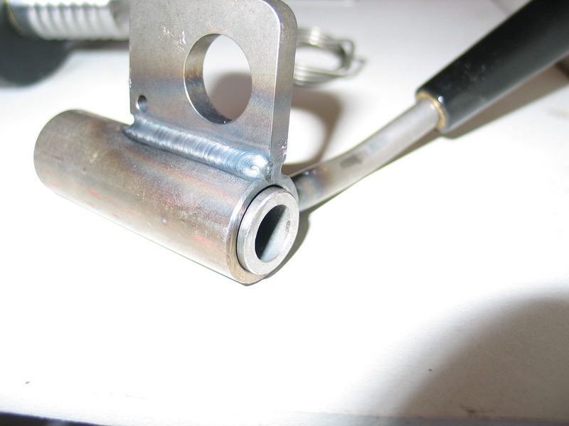
Install the release lever spring onto the release lever assembly, as shown. | ||||||||||||||||||||||||||||||||||||||||||||||||||||||||||||||||||||||||||||||||||||||||||||||||||||||||||||||||||||||||||||||||||||||||||||||||||||||||||||||||||||||||||||||||||||||||||||||||||||||||||||||||||||||||||||||||||||||||||||||||||||||||||||||||||||||||||||||||||||||||||||||||||||||||||||||||||||||||||||||||||||||||||||
 |
Alternate view of the release lever spring properly installed onto the release lever assembly. | ||||||||||||||||||||||||||||||||||||||||||||||||||||||||||||||||||||||||||||||||||||||||||||||||||||||||||||||||||||||||||||||||||||||||||||||||||||||||||||||||||||||||||||||||||||||||||||||||||||||||||||||||||||||||||||||||||||||||||||||||||||||||||||||||||||||||||||||||||||||||||||||||||||||||||||||||||||||||||||||||||||||||||||
 |
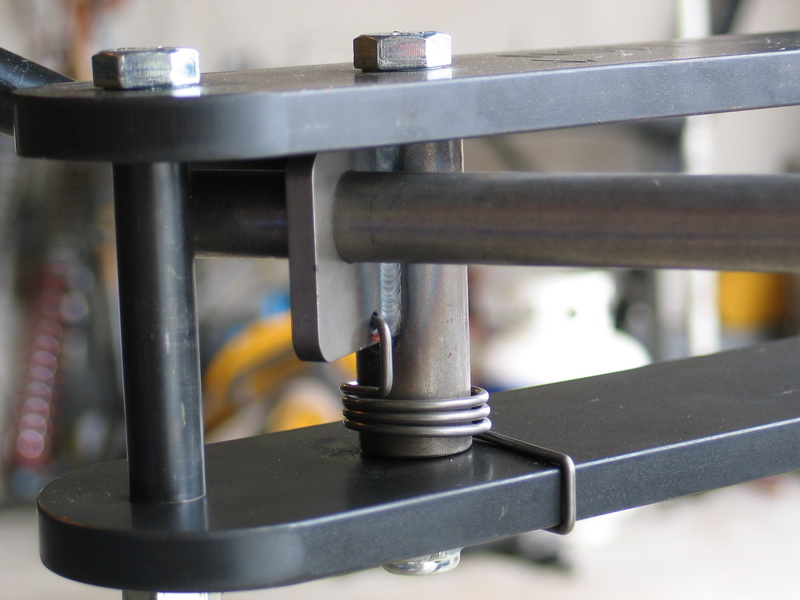
Install the release lever assembly with sleeve and spring, back between the pivot arms. With the assembly installed, hook the end of the spring over the lower pivot arm, as shown. |
||||||||||||||||||||||||||||||||||||||||||||||||||||||||||||||||||||||||||||||||||||||||||||||||||||||||||||||||||||||||||||||||||||||||||||||||||||||||||||||||||||||||||||||||||||||||||||||||||||||||||||||||||||||||||||||||||||||||||||||||||||||||||||||||||||||||||||||||||||||||||||||||||||||||||||||||||||||||||||||||||||||||||||
 |
Make sure the assembly and spring are installed in the correct orientation, as shown. The lower pivot arm is uppermost in this picture. |
||||||||||||||||||||||||||||||||||||||||||||||||||||||||||||||||||||||||||||||||||||||||||||||||||||||||||||||||||||||||||||||||||||||||||||||||||||||||||||||||||||||||||||||||||||||||||||||||||||||||||||||||||||||||||||||||||||||||||||||||||||||||||||||||||||||||||||||||||||||||||||||||||||||||||||||||||||||||||||||||||||||||||||
 |
Another view of properly installed release lever assembly. In this pic, the top side of the bender is uppermost. |
||||||||||||||||||||||||||||||||||||||||||||||||||||||||||||||||||||||||||||||||||||||||||||||||||||||||||||||||||||||||||||||||||||||||||||||||||||||||||||||||||||||||||||||||||||||||||||||||||||||||||||||||||||||||||||||||||||||||||||||||||||||||||||||||||||||||||||||||||||||||||||||||||||||||||||||||||||||||||||||||||||||||||||
 |
View of the correct position and orientation of the spring end hooked over the lower pivot arm. | ||||||||||||||||||||||||||||||||||||||||||||||||||||||||||||||||||||||||||||||||||||||||||||||||||||||||||||||||||||||||||||||||||||||||||||||||||||||||||||||||||||||||||||||||||||||||||||||||||||||||||||||||||||||||||||||||||||||||||||||||||||||||||||||||||||||||||||||||||||||||||||||||||||||||||||||||||||||||||||||||||||||||||||
 |
Reinstall and tighten the nut and bolt. | ||||||||||||||||||||||||||||||||||||||||||||||||||||||||||||||||||||||||||||||||||||||||||||||||||||||||||||||||||||||||||||||||||||||||||||||||||||||||||||||||||||||||||||||||||||||||||||||||||||||||||||||||||||||||||||||||||||||||||||||||||||||||||||||||||||||||||||||||||||||||||||||||||||||||||||||||||||||||||||||||||||||||||||
 |
Turn the bender around so that you can work on the main arms. Remove the nut and washer from the innermost position of the main arms. This is the larger of the two nuts on the main arms. |
||||||||||||||||||||||||||||||||||||||||||||||||||||||||||||||||||||||||||||||||||||||||||||||||||||||||||||||||||||||||||||||||||||||||||||||||||||||||||||||||||||||||||||||||||||||||||||||||||||||||||||||||||||||||||||||||||||||||||||||||||||||||||||||||||||||||||||||||||||||||||||||||||||||||||||||||||||||||||||||||||||||||||||
 |
Remove the bolt, washer, and sleeve. | ||||||||||||||||||||||||||||||||||||||||||||||||||||||||||||||||||||||||||||||||||||||||||||||||||||||||||||||||||||||||||||||||||||||||||||||||||||||||||||||||||||||||||||||||||||||||||||||||||||||||||||||||||||||||||||||||||||||||||||||||||||||||||||||||||||||||||||||||||||||||||||||||||||||||||||||||||||||||||||||||||||||||||||
 |
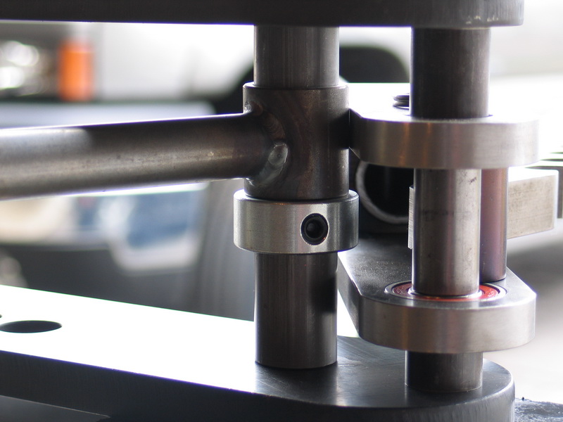
Install the collar and anti-spring-back rod eye over the removed sleeve. Do not tighten the set screw in the collar yet. |
||||||||||||||||||||||||||||||||||||||||||||||||||||||||||||||||||||||||||||||||||||||||||||||||||||||||||||||||||||||||||||||||||||||||||||||||||||||||||||||||||||||||||||||||||||||||||||||||||||||||||||||||||||||||||||||||||||||||||||||||||||||||||||||||||||||||||||||||||||||||||||||||||||||||||||||||||||||||||||||||||||||||||||
 |
Re-position the sleeve between the main arms and insert the anti-spring-back rod through the hole in the flag on the release lever assembly. As shown, when the rod is installed in the proper orientation, the collar will be on the lower side of the sleeve, below the rod eye. |
||||||||||||||||||||||||||||||||||||||||||||||||||||||||||||||||||||||||||||||||||||||||||||||||||||||||||||||||||||||||||||||||||||||||||||||||||||||||||||||||||||||||||||||||||||||||||||||||||||||||||||||||||||||||||||||||||||||||||||||||||||||||||||||||||||||||||||||||||||||||||||||||||||||||||||||||||||||||||||||||||||||||||||
 |
Make sure the collar is below the rod eye when you install the sleeve. | ||||||||||||||||||||||||||||||||||||||||||||||||||||||||||||||||||||||||||||||||||||||||||||||||||||||||||||||||||||||||||||||||||||||||||||||||||||||||||||||||||||||||||||||||||||||||||||||||||||||||||||||||||||||||||||||||||||||||||||||||||||||||||||||||||||||||||||||||||||||||||||||||||||||||||||||||||||||||||||||||||||||||||||
 |
View of the anti-spring-back rod positioned through the hole in the flag on the release lever assembly. | ||||||||||||||||||||||||||||||||||||||||||||||||||||||||||||||||||||||||||||||||||||||||||||||||||||||||||||||||||||||||||||||||||||||||||||||||||||||||||||||||||||||||||||||||||||||||||||||||||||||||||||||||||||||||||||||||||||||||||||||||||||||||||||||||||||||||||||||||||||||||||||||||||||||||||||||||||||||||||||||||||||||||||||
 |
Re-install the bolt through the main arms and tighten. | ||||||||||||||||||||||||||||||||||||||||||||||||||||||||||||||||||||||||||||||||||||||||||||||||||||||||||||||||||||||||||||||||||||||||||||||||||||||||||||||||||||||||||||||||||||||||||||||||||||||||||||||||||||||||||||||||||||||||||||||||||||||||||||||||||||||||||||||||||||||||||||||||||||||||||||||||||||||||||||||||||||||||||||
 |
Set the bender down in the normal orientation, as shown, and test the operation of the anti-spring-back lever as follows: Pull the main arms and pivot arms apart, as shown. They should open smoothly with no binding or resistance. |
||||||||||||||||||||||||||||||||||||||||||||||||||||||||||||||||||||||||||||||||||||||||||||||||||||||||||||||||||||||||||||||||||||||||||||||||||||||||||||||||||||||||||||||||||||||||||||||||||||||||||||||||||||||||||||||||||||||||||||||||||||||||||||||||||||||||||||||||||||||||||||||||||||||||||||||||||||||||||||||||||||||||||||
 |
To close the arms, press the release handle towards the main arms and, while holding slight pressure on it, swing the pivot arms back towards the main arms, closing the bender. | ||||||||||||||||||||||||||||||||||||||||||||||||||||||||||||||||||||||||||||||||||||||||||||||||||||||||||||||||||||||||||||||||||||||||||||||||||||||||||||||||||||||||||||||||||||||||||||||||||||||||||||||||||||||||||||||||||||||||||||||||||||||||||||||||||||||||||||||||||||||||||||||||||||||||||||||||||||||||||||||||||||||||||||
 |
If there is any binding or resistance felt, it is likely due to slight misalignment between the anti-spring-back rod and the hole in the flag on the release lever assembly. The anti-spring-back rod MUST be located parallel to the main and pivot arms for proper operation. Slight adjustments can be made to the position of the anti-spring-back rod eye on the sleeve.
|
||||||||||||||||||||||||||||||||||||||||||||||||||||||||||||||||||||||||||||||||||||||||||||||||||||||||||||||||||||||||||||||||||||||||||||||||||||||||||||||||||||||||||||||||||||||||||||||||||||||||||||||||||||||||||||||||||||||||||||||||||||||||||||||||||||||||||||||||||||||||||||||||||||||||||||||||||||||||||||||||||||||||||||
 |
When the action is smooth, tighten the set screw in the collar. Cycle the pivot arm several times to ensure the anti-spring-back rod is not binding through the release lever assembly. Some fine tuning of the collar position (up or down) may be required for smooth operation. DO NOT use any grease on the anti-spring-back rod. |
||||||||||||||||||||||||||||||||||||||||||||||||||||||||||||||||||||||||||||||||||||||||||||||||||||||||||||||||||||||||||||||||||||||||||||||||||||||||||||||||||||||||||||||||||||||||||||||||||||||||||||||||||||||||||||||||||||||||||||||||||||||||||||||||||||||||||||||||||||||||||||||||||||||||||||||||||||||||||||||||||||||||||||
Mounting the BenderWith the anti-spring-back kit installed, the next step is to mount the bender to a sturdy work stand. JMR supply a stand for this purpose, but it's also a fairly easy thing to fabricate. I chose to make my own. |
|||||||||||||||||||||||||||||||||||||||||||||||||||||||||||||||||||||||||||||||||||||||||||||||||||||||||||||||||||||||||||||||||||||||||||||||||||||||||||||||||||||||||||||||||||||||||||||||||||||||||||||||||||||||||||||||||||||||||||||||||||||||||||||||||||||||||||||||||||||||||||||||||||||||||||||||||||||||||||||||||||||||||||||
 |
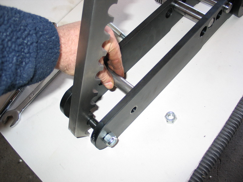
Remove the nuts and washers from both bolts in the main arms... | ||||||||||||||||||||||||||||||||||||||||||||||||||||||||||||||||||||||||||||||||||||||||||||||||||||||||||||||||||||||||||||||||||||||||||||||||||||||||||||||||||||||||||||||||||||||||||||||||||||||||||||||||||||||||||||||||||||||||||||||||||||||||||||||||||||||||||||||||||||||||||||||||||||||||||||||||||||||||||||||||||||||||||||
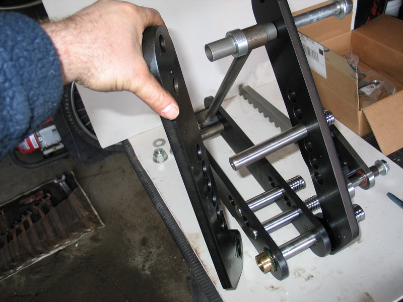 |
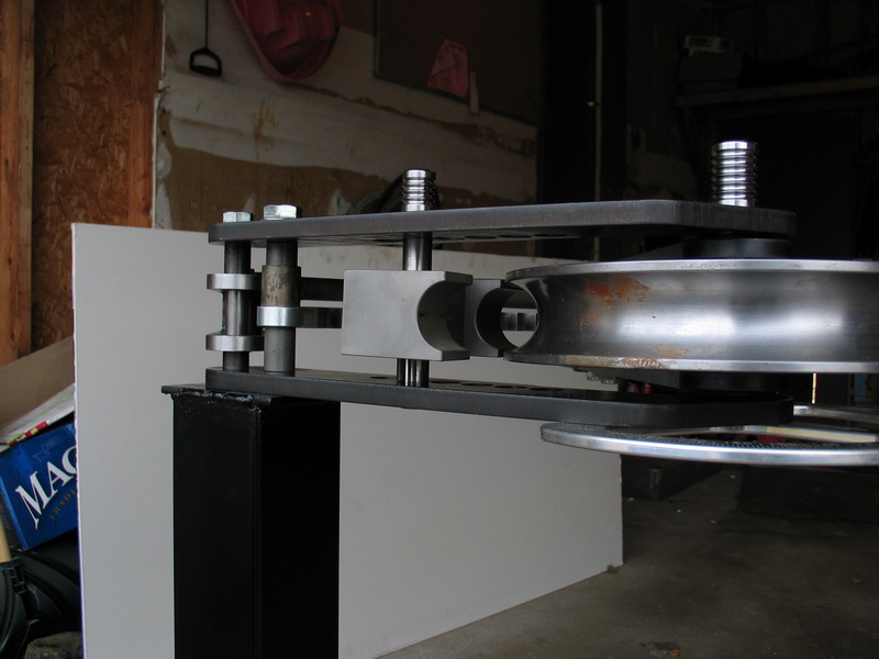
...and slip the lower main arm off the bender assembly. Note the large bronze bushing that connects the main arms and pivot arms at the pivot point. We'll see this again, as it is a great feature that not only ensures smooth, accurate bending, but also prevents the bender falling apart when you change dies. |
||||||||||||||||||||||||||||||||||||||||||||||||||||||||||||||||||||||||||||||||||||||||||||||||||||||||||||||||||||||||||||||||||||||||||||||||||||||||||||||||||||||||||||||||||||||||||||||||||||||||||||||||||||||||||||||||||||||||||||||||||||||||||||||||||||||||||||||||||||||||||||||||||||||||||||||||||||||||||||||||||||||||||||
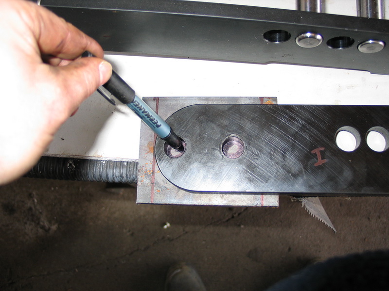 |
I traced the bolt pattern from the two main arm bolt holes onto a chunk of 1/4" steel plate... | ||||||||||||||||||||||||||||||||||||||||||||||||||||||||||||||||||||||||||||||||||||||||||||||||||||||||||||||||||||||||||||||||||||||||||||||||||||||||||||||||||||||||||||||||||||||||||||||||||||||||||||||||||||||||||||||||||||||||||||||||||||||||||||||||||||||||||||||||||||||||||||||||||||||||||||||||||||||||||||||||||||||||||||
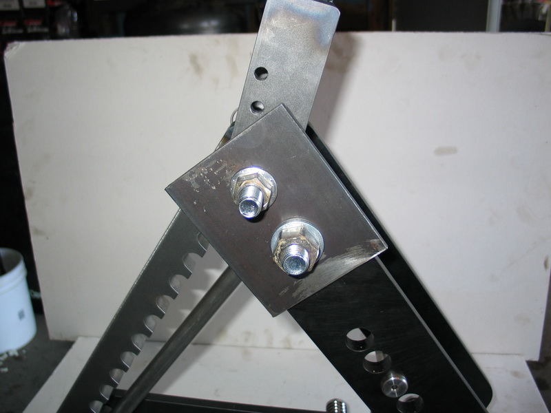 |
...then drilled the holes and bolted the plate to the underside of the lower main arm. This plate will become the top of my stand. Note that I replaced the supplied Nylok locking nuts with all-metal deformed-thread locknuts since I will be welding the plate to the top of the stand and didn't want the heat to transfer and melt the nylon in the stock locknuts. The nuts must be extremely tight to prevent the main arms from "scissoring" against each other. I used 230 ft/lbs for the smaller, outer bolt and about 300 ft/lbs for the larger, outside bolt. |
||||||||||||||||||||||||||||||||||||||||||||||||||||||||||||||||||||||||||||||||||||||||||||||||||||||||||||||||||||||||||||||||||||||||||||||||||||||||||||||||||||||||||||||||||||||||||||||||||||||||||||||||||||||||||||||||||||||||||||||||||||||||||||||||||||||||||||||||||||||||||||||||||||||||||||||||||||||||||||||||||||||||||||
 |
With the top of the stand made, I needed to choose a location for the bender and make the base. When choosing a location and the orientation of the bender on its stand, consider which way the tube will be fed and how long the pieces of tube you will bend are. I found the best choice to be at the front of the shop, close to the door, on the right-hand side (right when facing out the door), with the "back side" of the bender closest to the door (so tube will be loaded from outside the door). |
||||||||||||||||||||||||||||||||||||||||||||||||||||||||||||||||||||||||||||||||||||||||||||||||||||||||||||||||||||||||||||||||||||||||||||||||||||||||||||||||||||||||||||||||||||||||||||||||||||||||||||||||||||||||||||||||||||||||||||||||||||||||||||||||||||||||||||||||||||||||||||||||||||||||||||||||||||||||||||||||||||||||||||
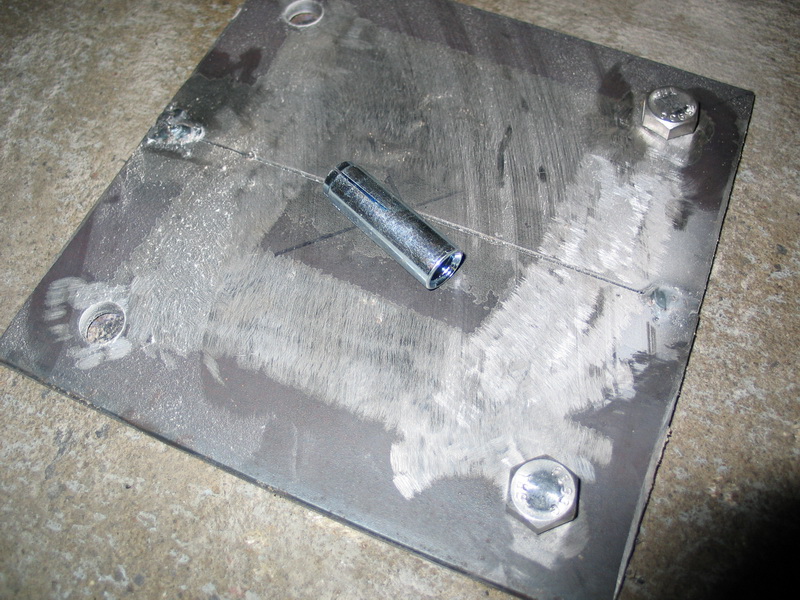 |
I wanted a good sturdy base for the stand, so I laid out a 6" square bolt pattern, again in 1/4" steel plate, for 1/2" mounting bolts. The stand will be bolted to my concrete garage floor, so I picked up four of these 1/2" concrete anchors. |
||||||||||||||||||||||||||||||||||||||||||||||||||||||||||||||||||||||||||||||||||||||||||||||||||||||||||||||||||||||||||||||||||||||||||||||||||||||||||||||||||||||||||||||||||||||||||||||||||||||||||||||||||||||||||||||||||||||||||||||||||||||||||||||||||||||||||||||||||||||||||||||||||||||||||||||||||||||||||||||||||||||||||||
 |
This style of anchor is designed to be driven into a hole in the concrete until it is flush with the floor (this lets me completely remove the bender if need be). The action of driving the anchor into the concrete splays the lower end out so that it anchors securely in the concrete. |
||||||||||||||||||||||||||||||||||||||||||||||||||||||||||||||||||||||||||||||||||||||||||||||||||||||||||||||||||||||||||||||||||||||||||||||||||||||||||||||||||||||||||||||||||||||||||||||||||||||||||||||||||||||||||||||||||||||||||||||||||||||||||||||||||||||||||||||||||||||||||||||||||||||||||||||||||||||||||||||||||||||||||||
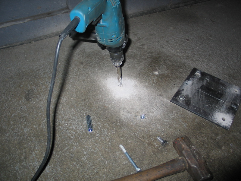 |
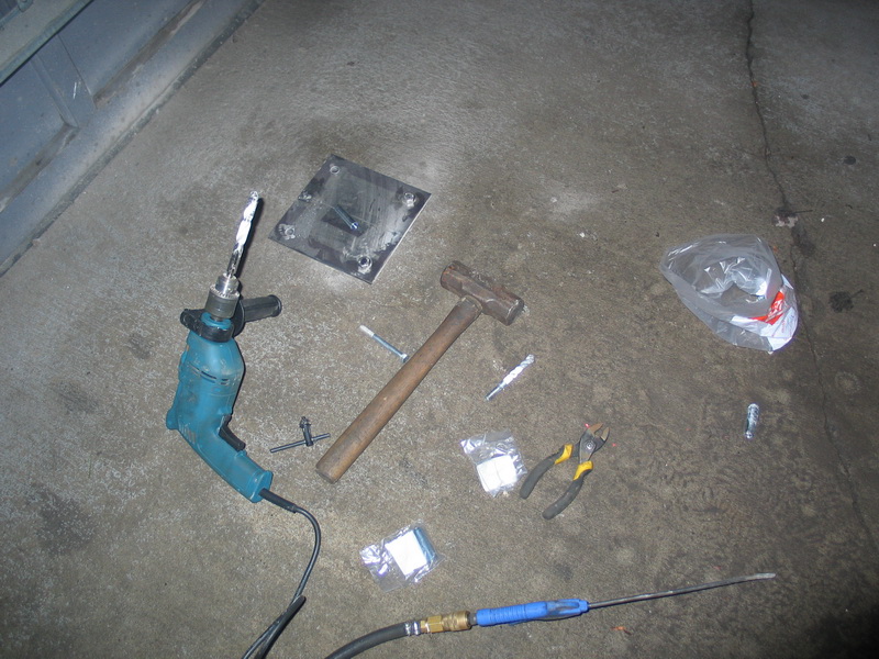
A decent hammer drill with the correct-size concrete-drilling bit is the only way to make a decent hole in a concrete floor. Don't even try using a regular drill or, god forbid, a regular drill bit!! | ||||||||||||||||||||||||||||||||||||||||||||||||||||||||||||||||||||||||||||||||||||||||||||||||||||||||||||||||||||||||||||||||||||||||||||||||||||||||||||||||||||||||||||||||||||||||||||||||||||||||||||||||||||||||||||||||||||||||||||||||||||||||||||||||||||||||||||||||||||||||||||||||||||||||||||||||||||||||||||||||||||||||||||
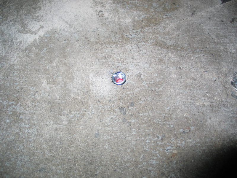 |
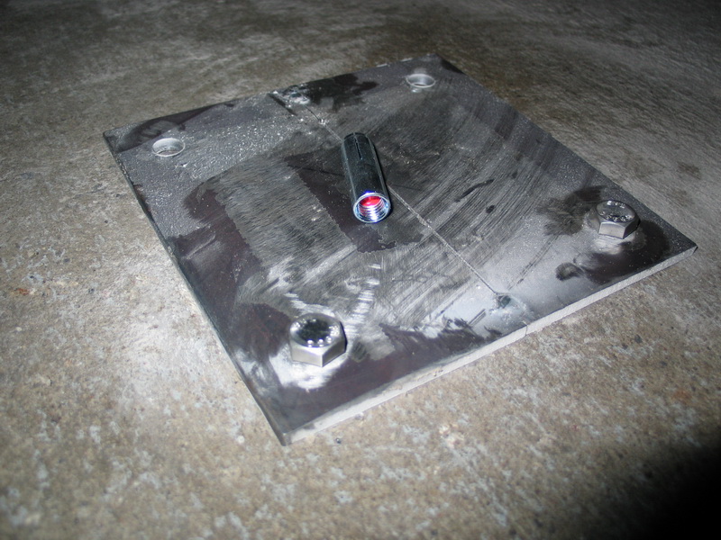
Anchor driven flush with the floor. These anchors are sold under numerous brand names, and you should be able to get them at any of the major hardware or building-supply stores. |
||||||||||||||||||||||||||||||||||||||||||||||||||||||||||||||||||||||||||||||||||||||||||||||||||||||||||||||||||||||||||||||||||||||||||||||||||||||||||||||||||||||||||||||||||||||||||||||||||||||||||||||||||||||||||||||||||||||||||||||||||||||||||||||||||||||||||||||||||||||||||||||||||||||||||||||||||||||||||||||||||||||||||||
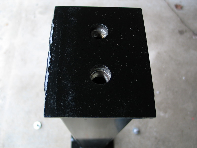 |
To finish the stand, I simply welded a 32" long piece of square tube to the base plate, bolted the base plate to the concrete using the anchors, and then welded the top plate to the top of the square tube. This is a view of the top plate. |
||||||||||||||||||||||||||||||||||||||||||||||||||||||||||||||||||||||||||||||||||||||||||||||||||||||||||||||||||||||||||||||||||||||||||||||||||||||||||||||||||||||||||||||||||||||||||||||||||||||||||||||||||||||||||||||||||||||||||||||||||||||||||||||||||||||||||||||||||||||||||||||||||||||||||||||||||||||||||||||||||||||||||||
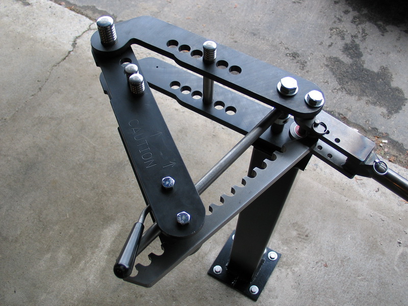 |
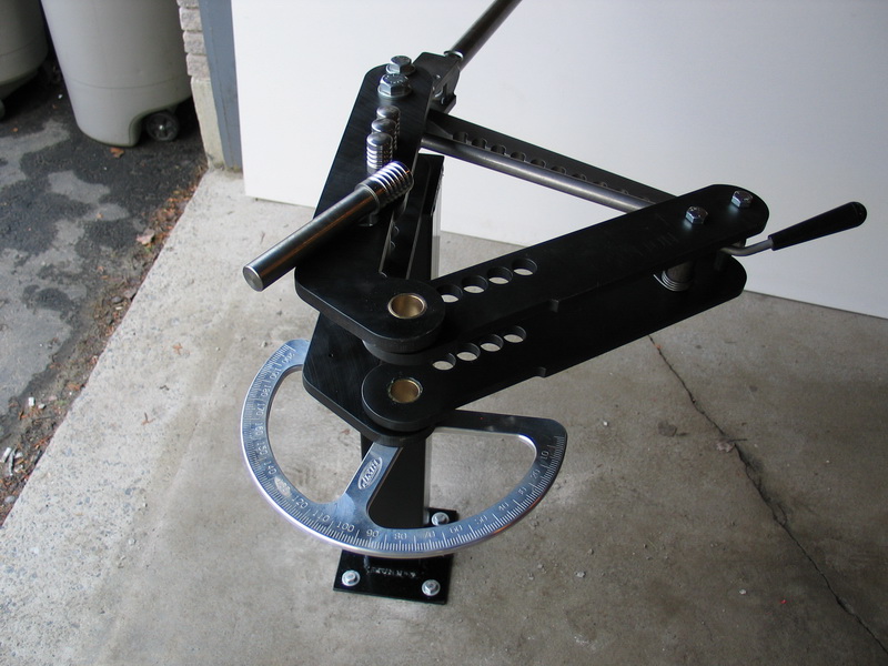
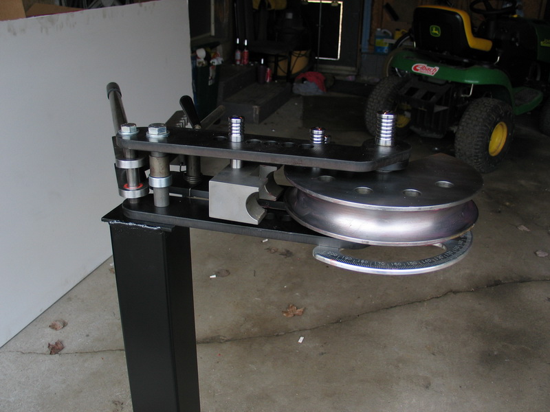
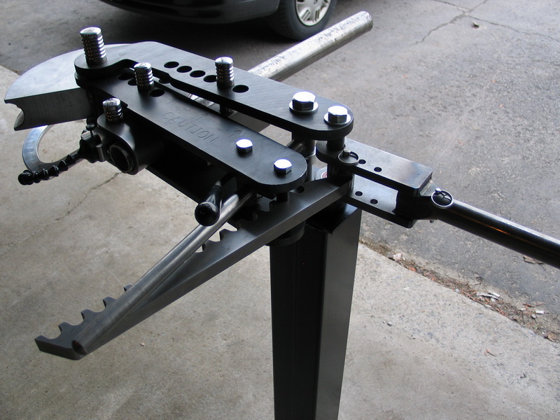
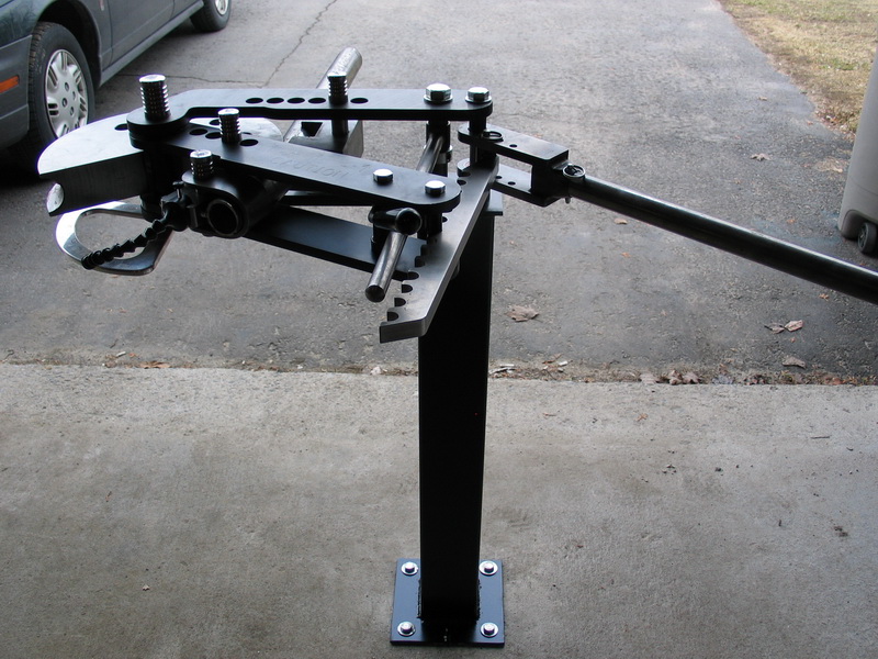
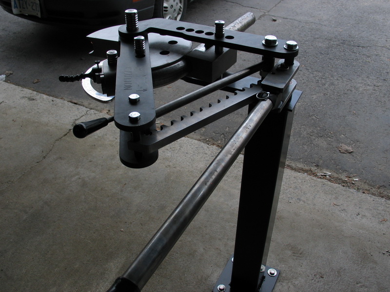
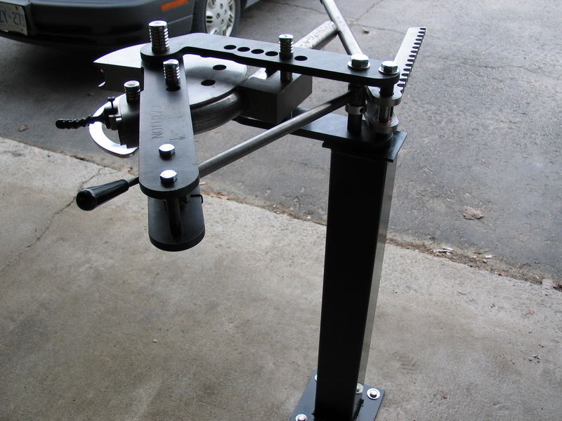
Bender mounted on its stand. This is at the front right of the shop, just in front of the door opening. |
||||||||||||||||||||||||||||||||||||||||||||||||||||||||||||||||||||||||||||||||||||||||||||||||||||||||||||||||||||||||||||||||||||||||||||||||||||||||||||||||||||||||||||||||||||||||||||||||||||||||||||||||||||||||||||||||||||||||||||||||||||||||||||||||||||||||||||||||||||||||||||||||||||||||||||||||||||||||||||||||||||||||||||
 |
Another view of the bender mounted on its stand. Note the orientation of the bender - in this installation, long pieces of tube will be fed into the bender from outside the door. You can also easily customize the stand to your liking by adding hooks or mounting points for tooling, die sets, etc. |
||||||||||||||||||||||||||||||||||||||||||||||||||||||||||||||||||||||||||||||||||||||||||||||||||||||||||||||||||||||||||||||||||||||||||||||||||||||||||||||||||||||||||||||||||||||||||||||||||||||||||||||||||||||||||||||||||||||||||||||||||||||||||||||||||||||||||||||||||||||||||||||||||||||||||||||||||||||||||||||||||||||||||||
Installing the Degree RingThe final step before cranking out an intricate tubular chassis with the bender is to install the degree ring. |
|||||||||||||||||||||||||||||||||||||||||||||||||||||||||||||||||||||||||||||||||||||||||||||||||||||||||||||||||||||||||||||||||||||||||||||||||||||||||||||||||||||||||||||||||||||||||||||||||||||||||||||||||||||||||||||||||||||||||||||||||||||||||||||||||||||||||||||||||||||||||||||||||||||||||||||||||||||||||||||||||||||||||||||
|
This is the degree ring for the JMR bender. It is part number DGW100, and includes the machined aluminum degree ring, the flexible pointer, and two mounting screws. |
||||||||||||||||||||||||||||||||||||||||||||||||||||||||||||||||||||||||||||||||||||||||||||||||||||||||||||||||||||||||||||||||||||||||||||||||||||||||||||||||||||||||||||||||||||||||||||||||||||||||||||||||||||||||||||||||||||||||||||||||||||||||||||||||||||||||||||||||||||||||||||||||||||||||||||||||||||||||||||||||||||||||||||
|
The JMR degree ring is a very nice piece of machined aluminum - rugged, accurate, and very easy to read - even during bending. |
||||||||||||||||||||||||||||||||||||||||||||||||||||||||||||||||||||||||||||||||||||||||||||||||||||||||||||||||||||||||||||||||||||||||||||||||||||||||||||||||||||||||||||||||||||||||||||||||||||||||||||||||||||||||||||||||||||||||||||||||||||||||||||||||||||||||||||||||||||||||||||||||||||||||||||||||||||||||||||||||||||||||||||
 |
The degree ring mounts on the underside of the lower main arm. The large hole fits over the pivot pin... | ||||||||||||||||||||||||||||||||||||||||||||||||||||||||||||||||||||||||||||||||||||||||||||||||||||||||||||||||||||||||||||||||||||||||||||||||||||||||||||||||||||||||||||||||||||||||||||||||||||||||||||||||||||||||||||||||||||||||||||||||||||||||||||||||||||||||||||||||||||||||||||||||||||||||||||||||||||||||||||||||||||||||||||
 |
..and the ring is attached to the lower main arm with the two supplied Allen-head screws. | ||||||||||||||||||||||||||||||||||||||||||||||||||||||||||||||||||||||||||||||||||||||||||||||||||||||||||||||||||||||||||||||||||||||||||||||||||||||||||||||||||||||||||||||||||||||||||||||||||||||||||||||||||||||||||||||||||||||||||||||||||||||||||||||||||||||||||||||||||||||||||||||||||||||||||||||||||||||||||||||||||||||||||||
 |
Degree ring installed. At this point, all that is required is to install the die and follower-block of your choice and start bending. |
||||||||||||||||||||||||||||||||||||||||||||||||||||||||||||||||||||||||||||||||||||||||||||||||||||||||||||||||||||||||||||||||||||||||||||||||||||||||||||||||||||||||||||||||||||||||||||||||||||||||||||||||||||||||||||||||||||||||||||||||||||||||||||||||||||||||||||||||||||||||||||||||||||||||||||||||||||||||||||||||||||||||||||
Features and Benefits of the JMR MB1000 DesignLike the JMR tube notcher I reviewed in last month's article, the JMR tube bender is a serious, professional-quality tool. It is designed for the serious fabricator looking for a top-quality bender that is precision built, rugged, and able to handle virtually any duty, including 4130 Chrome-moly, stainless steel, 2.5" OD tube, 0.25" wall tube, Schedule 40 pipe, and square tubing (HSS). The design and construction of the JMR MB1000 Manual Tube Bender offers the following features and benefits:
Capacities:
Available accessories include:
|
|||||||||||||||||||||||||||||||||||||||||||||||||||||||||||||||||||||||||||||||||||||||||||||||||||||||||||||||||||||||||||||||||||||||||||||||||||||||||||||||||||||||||||||||||||||||||||||||||||||||||||||||||||||||||||||||||||||||||||||||||||||||||||||||||||||||||||||||||||||||||||||||||||||||||||||||||||||||||||||||||||||||||||||
 |
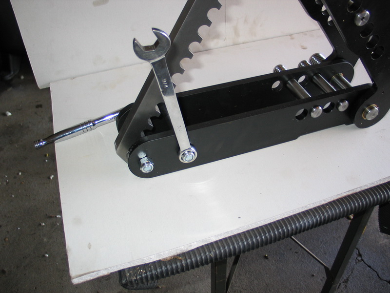
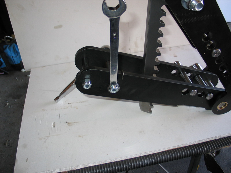
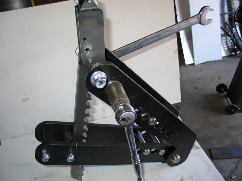
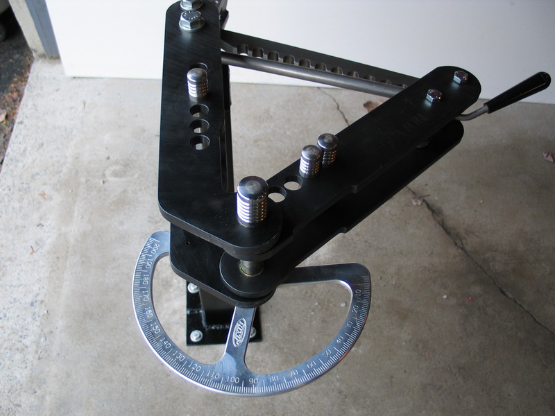
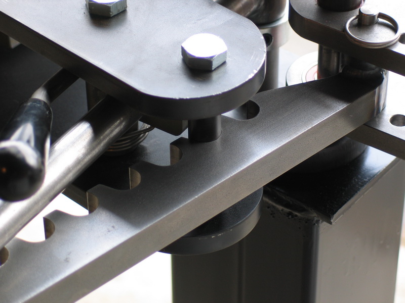
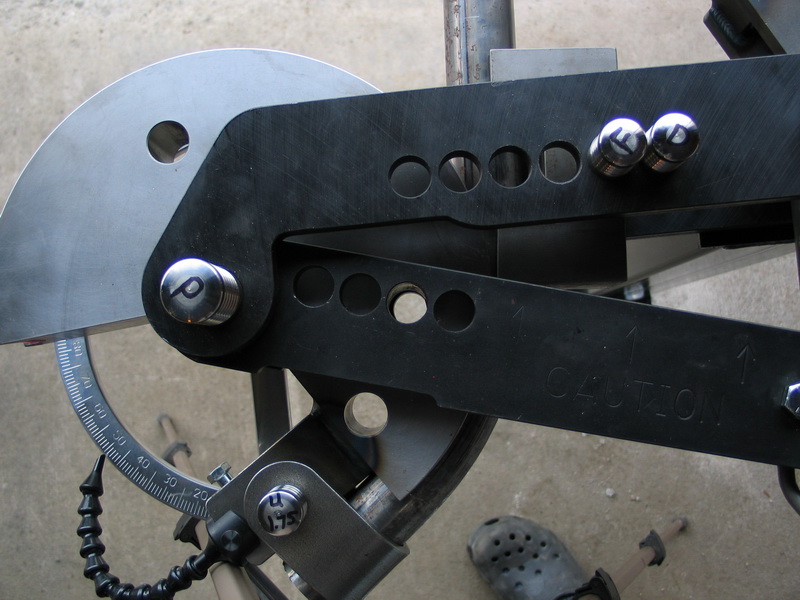
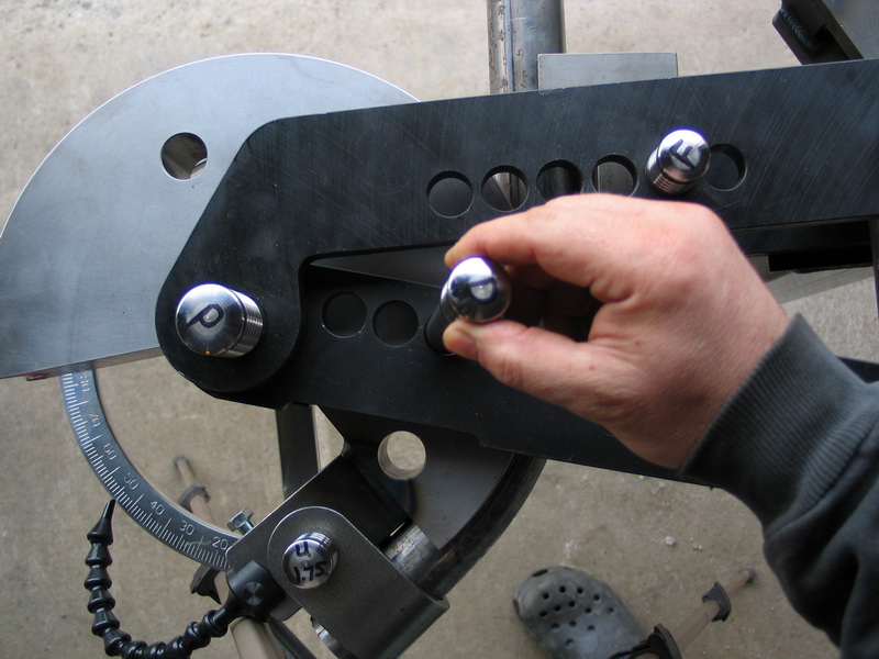
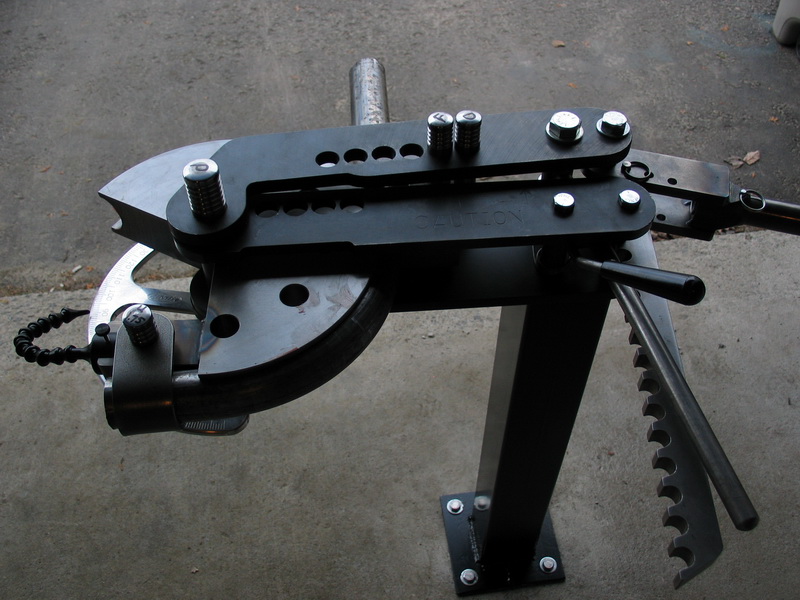
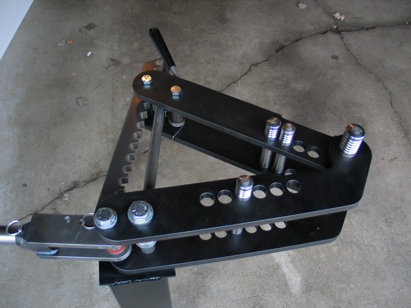
The JMR has a unique 3-speed drive mechanism. The lever can be connected to the drive rack using any one of the three pairs of holes. The change is quick and easy to make using the quick-release pin. The position closest to the main arms (shown) provides the greatest leverage - great for large OD or heavy-wall materials. The position furthest from the main arms provides the least leverage, but the greatest speed of bending - great for small OD or thin-wall materials. Essentially this clever design provides an adjustable lever that allows the user to trade leverage for speed - which is the principal operating principle of any lever. |
||||||||||||||||||||||||||||||||||||||||||||||||||||||||||||||||||||||||||||||||||||||||||||||||||||||||||||||||||||||||||||||||||||||||||||||||||||||||||||||||||||||||||||||||||||||||||||||||||||||||||||||||||||||||||||||||||||||||||||||||||||||||||||||||||||||||||||||||||||||||||||||||||||||||||||||||||||||||||||||||||||||||||||
|
Here's the theory, for those interested: Work is force times distance (W = F x d). By looking at the equation we can see that if work remains constant, increasing force decreases distance or increasing distance decreases force. A lever is a simple machine that trades force for distance or vice versa. We all use levers every single day. The simplest example is a door. Imagine you open a door by pushing near the hinges. Now imagine you open the same door by pushing near the handle. In either case the same amount of work is done. But, when you push near the hinges you must push harder (force is greater) but over a smaller distance (distance is less). When you push near the handle less force is required, but you must push for a greater distance. The door is a lever that trades distance for force - putting the handle on the opposite side of the door from the hinges makes it easier to open and close. Other examples of levers that cost distance but payback in force are a bottle opener and a crowbar. |
||||||||||||||||||||||||||||||||||||||||||||||||||||||||||||||||||||||||||||||||||||||||||||||||||||||||||||||||||||||||||||||||||||||||||||||||||||||||||||||||||||||||||||||||||||||||||||||||||||||||||||||||||||||||||||||||||||||||||||||||||||||||||||||||||||||||||||||||||||||||||||||||||||||||||||||||||||||||||||||||||||||||||||
Normally this is how we think of using a lever - to make things easier - to trade distance for force. But many types of lever are also used to trade force for distance - that is, they cost force but payback in distance (or speed). Common examples include a brrom or a baseball bat. By providing for adjustable leverage, the JMR bender allows us to choose the balance of force vs. distance (where distance really equates to how fast the bend is made, since the greater the distance the handle must be pulled, the longer the bend will take). The difference between the position is not trivial either - it's actually quite dramatic. For example - on "max leverage", a single pull on the handle opens the arms about 1/2". In contrast - on "max speed", the same pull opens the arms about 2-1/2" - a 500% increase in speed!! You can see the three-speed mechanism in operation in the Instructional Video. |
|||||||||||||||||||||||||||||||||||||||||||||||||||||||||||||||||||||||||||||||||||||||||||||||||||||||||||||||||||||||||||||||||||||||||||||||||||||||||||||||||||||||||||||||||||||||||||||||||||||||||||||||||||||||||||||||||||||||||||||||||||||||||||||||||||||||||||||||||||||||||||||||||||||||||||||||||||||||||||||||||||||||||||||
|
The arms of the JMR are massive 9/16" alloy steel that are heat treated, blanchard-ground, and completed with an anodized black finish for superior strength, durability, and corrosion resistance. |
||||||||||||||||||||||||||||||||||||||||||||||||||||||||||||||||||||||||||||||||||||||||||||||||||||||||||||||||||||||||||||||||||||||||||||||||||||||||||||||||||||||||||||||||||||||||||||||||||||||||||||||||||||||||||||||||||||||||||||||||||||||||||||||||||||||||||||||||||||||||||||||||||||||||||||||||||||||||||||||||||||||||||||
 |
All the pins are constructed from heat treated 4140 chrome-moly alloy steel. This is critical as the pins are subjected to tremendous loads. No bent pins or grade 8 bolt replacements required here! | ||||||||||||||||||||||||||||||||||||||||||||||||||||||||||||||||||||||||||||||||||||||||||||||||||||||||||||||||||||||||||||||||||||||||||||||||||||||||||||||||||||||||||||||||||||||||||||||||||||||||||||||||||||||||||||||||||||||||||||||||||||||||||||||||||||||||||||||||||||||||||||||||||||||||||||||||||||||||||||||||||||||||||||
|
JMR dies and follower-blocks are made from heat treated billet steel. follower-blocks are case hardened to a min depth of .050". All dies carry a lifetime warranty against breakage. |
||||||||||||||||||||||||||||||||||||||||||||||||||||||||||||||||||||||||||||||||||||||||||||||||||||||||||||||||||||||||||||||||||||||||||||||||||||||||||||||||||||||||||||||||||||||||||||||||||||||||||||||||||||||||||||||||||||||||||||||||||||||||||||||||||||||||||||||||||||||||||||||||||||||||||||||||||||||||||||||||||||||||||||
|
The JMR drive rack is precision machined from billet steel... | ||||||||||||||||||||||||||||||||||||||||||||||||||||||||||||||||||||||||||||||||||||||||||||||||||||||||||||||||||||||||||||||||||||||||||||||||||||||||||||||||||||||||||||||||||||||||||||||||||||||||||||||||||||||||||||||||||||||||||||||||||||||||||||||||||||||||||||||||||||||||||||||||||||||||||||||||||||||||||||||||||||||||||||
 |
... no flame-cut parts here! | ||||||||||||||||||||||||||||||||||||||||||||||||||||||||||||||||||||||||||||||||||||||||||||||||||||||||||||||||||||||||||||||||||||||||||||||||||||||||||||||||||||||||||||||||||||||||||||||||||||||||||||||||||||||||||||||||||||||||||||||||||||||||||||||||||||||||||||||||||||||||||||||||||||||||||||||||||||||||||||||||||||||||||||
|
The main and pivot arms of the JMR are held together by bronze bushings. Not only does this provide smoother, more precise action with less wear... |
||||||||||||||||||||||||||||||||||||||||||||||||||||||||||||||||||||||||||||||||||||||||||||||||||||||||||||||||||||||||||||||||||||||||||||||||||||||||||||||||||||||||||||||||||||||||||||||||||||||||||||||||||||||||||||||||||||||||||||||||||||||||||||||||||||||||||||||||||||||||||||||||||||||||||||||||||||||||||||||||||||||||||||
 |
... but it also prevents the pivot arms from falling off when the pivot pin is removed to change dies - a common problem with many other designs. | ||||||||||||||||||||||||||||||||||||||||||||||||||||||||||||||||||||||||||||||||||||||||||||||||||||||||||||||||||||||||||||||||||||||||||||||||||||||||||||||||||||||||||||||||||||||||||||||||||||||||||||||||||||||||||||||||||||||||||||||||||||||||||||||||||||||||||||||||||||||||||||||||||||||||||||||||||||||||||||||||||||||||||||
 |
The drive action of the JMR is supported by sealed roller bearings. | ||||||||||||||||||||||||||||||||||||||||||||||||||||||||||||||||||||||||||||||||||||||||||||||||||||||||||||||||||||||||||||||||||||||||||||||||||||||||||||||||||||||||||||||||||||||||||||||||||||||||||||||||||||||||||||||||||||||||||||||||||||||||||||||||||||||||||||||||||||||||||||||||||||||||||||||||||||||||||||||||||||||||||||
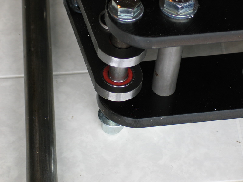 |
Again, this is the right way to build a precision, long-lasting, professional quality tool. | ||||||||||||||||||||||||||||||||||||||||||||||||||||||||||||||||||||||||||||||||||||||||||||||||||||||||||||||||||||||||||||||||||||||||||||||||||||||||||||||||||||||||||||||||||||||||||||||||||||||||||||||||||||||||||||||||||||||||||||||||||||||||||||||||||||||||||||||||||||||||||||||||||||||||||||||||||||||||||||||||||||||||||||
|
The machined aluminum degree ring and adjustable flexible pointer are superior to many other designs... | ||||||||||||||||||||||||||||||||||||||||||||||||||||||||||||||||||||||||||||||||||||||||||||||||||||||||||||||||||||||||||||||||||||||||||||||||||||||||||||||||||||||||||||||||||||||||||||||||||||||||||||||||||||||||||||||||||||||||||||||||||||||||||||||||||||||||||||||||||||||||||||||||||||||||||||||||||||||||||||||||||||||||||||
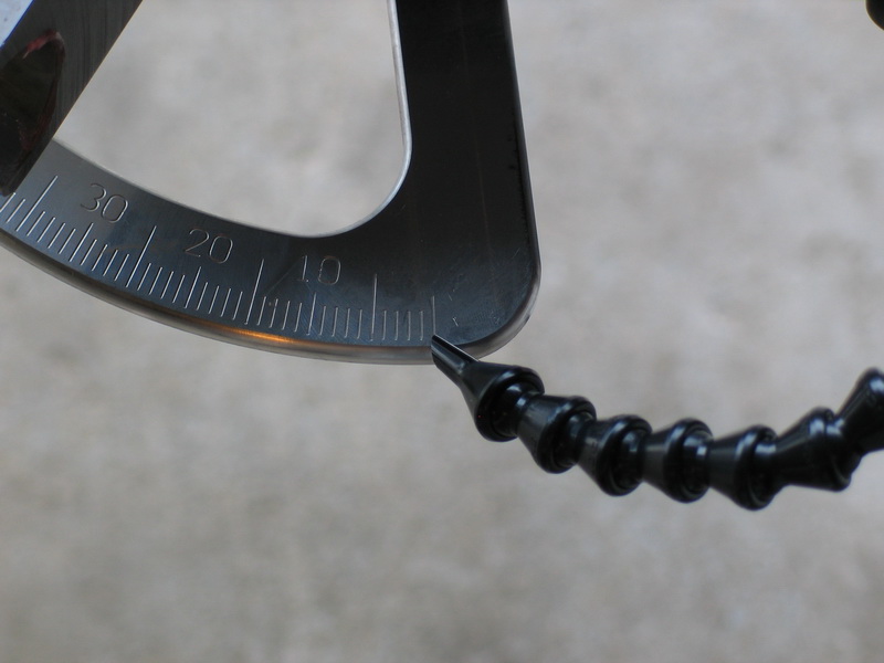 |
... and are clear and easy to adjust and read. | ||||||||||||||||||||||||||||||||||||||||||||||||||||||||||||||||||||||||||||||||||||||||||||||||||||||||||||||||||||||||||||||||||||||||||||||||||||||||||||||||||||||||||||||||||||||||||||||||||||||||||||||||||||||||||||||||||||||||||||||||||||||||||||||||||||||||||||||||||||||||||||||||||||||||||||||||||||||||||||||||||||||||||||
Selecting Die SetsThere are four variables involved in ordering a die set. They are:
|
|||||||||||||||||||||||||||||||||||||||||||||||||||||||||||||||||||||||||||||||||||||||||||||||||||||||||||||||||||||||||||||||||||||||||||||||||||||||||||||||||||||||||||||||||||||||||||||||||||||||||||||||||||||||||||||||||||||||||||||||||||||||||||||||||||||||||||||||||||||||||||||||||||||||||||||||||||||||||||||||||||||||||||||
|
This is a 240° 1" tube die set with a 3" CLR.
|
||||||||||||||||||||||||||||||||||||||||||||||||||||||||||||||||||||||||||||||||||||||||||||||||||||||||||||||||||||||||||||||||||||||||||||||||||||||||||||||||||||||||||||||||||||||||||||||||||||||||||||||||||||||||||||||||||||||||||||||||||||||||||||||||||||||||||||||||||||||||||||||||||||||||||||||||||||||||||||||||||||||||||||
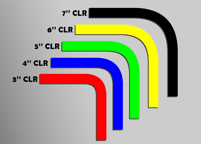 |
This diagram illustrates the differences between bends of different radii - that is, bends made with dies having different CLR's. Note that, generally, the tighter the bend, the greater the possibility for tube distortion or wrinkling in the bend, especially for thin-walled materials. I haven't tried every material type and thickness with every possible combination of dies (there are hundreds of possible combinations), but if you have questions or concerns about which CLR may be right for your application, the experts at JMR can help guide you. |
||||||||||||||||||||||||||||||||||||||||||||||||||||||||||||||||||||||||||||||||||||||||||||||||||||||||||||||||||||||||||||||||||||||||||||||||||||||||||||||||||||||||||||||||||||||||||||||||||||||||||||||||||||||||||||||||||||||||||||||||||||||||||||||||||||||||||||||||||||||||||||||||||||||||||||||||||||||||||||||||||||||||||||
Not every size die is available for every material in every different combination of degree and CLR - but there are over 75 JMR dies commonly available, and unless you're doing something really weird or custom - chances are the one you need is available. Having said that, JMR also have the capability to custom make a die to your specifications - so if you don't find what you need - they can make it for you! These tables show commonly available JMR die sets, for tube, pipe, and square tube: The " Min. Wall Thickness" column indicates the minimum recommended wall thickness for consistent high-quality wrinkle-free bends for the given CLR. Notes:
|
|||||||||||||||||||||||||||||||||||||||||||||||||||||||||||||||||||||||||||||||||||||||||||||||||||||||||||||||||||||||||||||||||||||||||||||||||||||||||||||||||||||||||||||||||||||||||||||||||||||||||||||||||||||||||||||||||||||||||||||||||||||||||||||||||||||||||||||||||||||||||||||||||||||||||||||||||||||||||||||||||||||||||||||
|
|||||||||||||||||||||||||||||||||||||||||||||||||||||||||||||||||||||||||||||||||||||||||||||||||||||||||||||||||||||||||||||||||||||||||||||||||||||||||||||||||||||||||||||||||||||||||||||||||||||||||||||||||||||||||||||||||||||||||||||||||||||||||||||||||||||||||||||||||||||||||||||||||||||||||||||||||||||||||||||||||||||||||||||
Operating the BenderOK, when we last left our bender we had installed the anti-spring-back kit, mounted it on a stand firmly bolted to the floor, and installed the degree ring. Now it's time to install the die of our choice and bend some tube. |
|||||||||||||||||||||||||||||||||||||||||||||||||||||||||||||||||||||||||||||||||||||||||||||||||||||||||||||||||||||||||||||||||||||||||||||||||||||||||||||||||||||||||||||||||||||||||||||||||||||||||||||||||||||||||||||||||||||||||||||||||||||||||||||||||||||||||||||||||||||||||||||||||||||||||||||||||||||||||||||||||||||||||||||
 |
Because we will reference them a lot in this section, as a quick review, here are the names of the pins again:
|
||||||||||||||||||||||||||||||||||||||||||||||||||||||||||||||||||||||||||||||||||||||||||||||||||||||||||||||||||||||||||||||||||||||||||||||||||||||||||||||||||||||||||||||||||||||||||||||||||||||||||||||||||||||||||||||||||||||||||||||||||||||||||||||||||||||||||||||||||||||||||||||||||||||||||||||||||||||||||||||||||||||||||||
|
Begin by removing the pivot pin so that you can install the die. |
||||||||||||||||||||||||||||||||||||||||||||||||||||||||||||||||||||||||||||||||||||||||||||||||||||||||||||||||||||||||||||||||||||||||||||||||||||||||||||||||||||||||||||||||||||||||||||||||||||||||||||||||||||||||||||||||||||||||||||||||||||||||||||||||||||||||||||||||||||||||||||||||||||||||||||||||||||||||||||||||||||||||||||
 |
Slip the die in place with the engraved size label facing up, and reinsert the pivot pin. | ||||||||||||||||||||||||||||||||||||||||||||||||||||||||||||||||||||||||||||||||||||||||||||||||||||||||||||||||||||||||||||||||||||||||||||||||||||||||||||||||||||||||||||||||||||||||||||||||||||||||||||||||||||||||||||||||||||||||||||||||||||||||||||||||||||||||||||||||||||||||||||||||||||||||||||||||||||||||||||||||||||||||||||
 |
Install the follower-block between the main arms, as close as possible to the die. Be sure to position the follower-block with the height-pin facing down, so that the pin positions the follower-block close to the correct vertical height. Secure the follower-block with the follower-block pin inserted through both main arms. |
||||||||||||||||||||||||||||||||||||||||||||||||||||||||||||||||||||||||||||||||||||||||||||||||||||||||||||||||||||||||||||||||||||||||||||||||||||||||||||||||||||||||||||||||||||||||||||||||||||||||||||||||||||||||||||||||||||||||||||||||||||||||||||||||||||||||||||||||||||||||||||||||||||||||||||||||||||||||||||||||||||||||||||
 |
With the height-pin down, the radius in the follower-block should be close to vertically level with the radius in the die, like this. The pin is not designed to hold the follower block at the precise height required - it actually floats vertically on the follower-block pin and will self-alighn onde the tube is inserted - but the height-pin holds it close to ease insertion of the tube. Lightly grease the working surface of the follower-block. |
||||||||||||||||||||||||||||||||||||||||||||||||||||||||||||||||||||||||||||||||||||||||||||||||||||||||||||||||||||||||||||||||||||||||||||||||||||||||||||||||||||||||||||||||||||||||||||||||||||||||||||||||||||||||||||||||||||||||||||||||||||||||||||||||||||||||||||||||||||||||||||||||||||||||||||||||||||||||||||||||||||||||||||
 |
Close the pivot arms against the main arms, using the anti-spring-back lever as required to do so. Insert the drive pin, locking the pivot arms and the die together. |
||||||||||||||||||||||||||||||||||||||||||||||||||||||||||||||||||||||||||||||||||||||||||||||||||||||||||||||||||||||||||||||||||||||||||||||||||||||||||||||||||||||||||||||||||||||||||||||||||||||||||||||||||||||||||||||||||||||||||||||||||||||||||||||||||||||||||||||||||||||||||||||||||||||||||||||||||||||||||||||||||||||||||||
 |
Grab some tube, making sure it is clean, dry, and free from defects. Move to the rear of the bender... |
||||||||||||||||||||||||||||||||||||||||||||||||||||||||||||||||||||||||||||||||||||||||||||||||||||||||||||||||||||||||||||||||||||||||||||||||||||||||||||||||||||||||||||||||||||||||||||||||||||||||||||||||||||||||||||||||||||||||||||||||||||||||||||||||||||||||||||||||||||||||||||||||||||||||||||||||||||||||||||||||||||||||||||
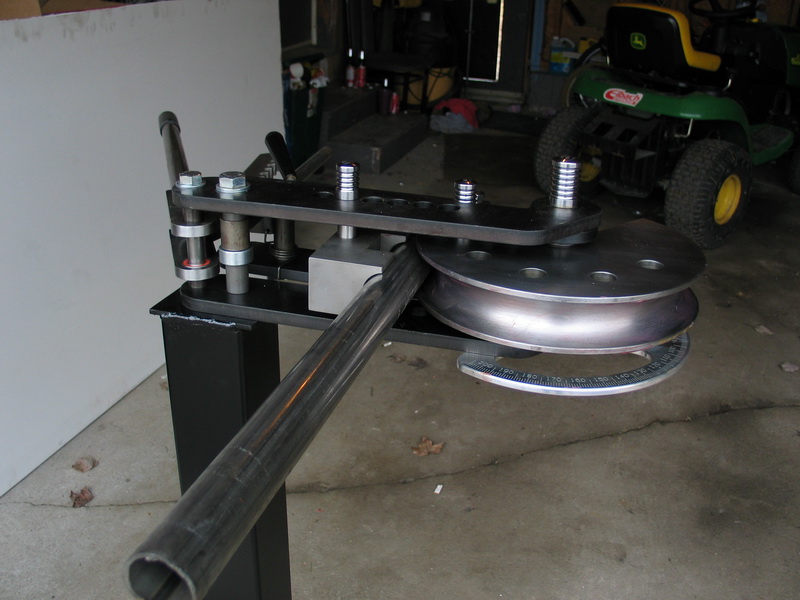 |
...and insert the tube from the rear... | ||||||||||||||||||||||||||||||||||||||||||||||||||||||||||||||||||||||||||||||||||||||||||||||||||||||||||||||||||||||||||||||||||||||||||||||||||||||||||||||||||||||||||||||||||||||||||||||||||||||||||||||||||||||||||||||||||||||||||||||||||||||||||||||||||||||||||||||||||||||||||||||||||||||||||||||||||||||||||||||||||||||||||||
 |
... positioning it between the follower-block and the die, as shown. | ||||||||||||||||||||||||||||||||||||||||||||||||||||||||||||||||||||||||||||||||||||||||||||||||||||||||||||||||||||||||||||||||||||||||||||||||||||||||||||||||||||||||||||||||||||||||||||||||||||||||||||||||||||||||||||||||||||||||||||||||||||||||||||||||||||||||||||||||||||||||||||||||||||||||||||||||||||||||||||||||||||||||||||
 |
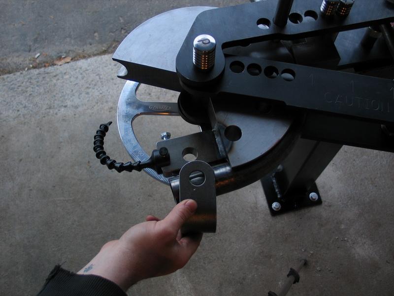
Position the U-strap around the end of the tube protruding from the front of the bender, and secure with the U-strap pin. | ||||||||||||||||||||||||||||||||||||||||||||||||||||||||||||||||||||||||||||||||||||||||||||||||||||||||||||||||||||||||||||||||||||||||||||||||||||||||||||||||||||||||||||||||||||||||||||||||||||||||||||||||||||||||||||||||||||||||||||||||||||||||||||||||||||||||||||||||||||||||||||||||||||||||||||||||||||||||||||||||||||||||||||
 |
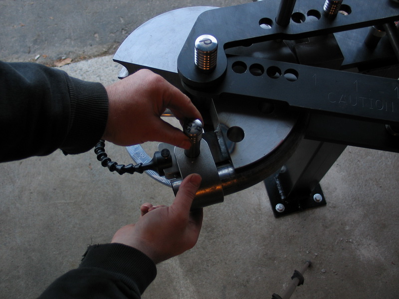
If not already in place, attach the pointer to the end of the drive lug on the die, and tighten the thumb screw. | ||||||||||||||||||||||||||||||||||||||||||||||||||||||||||||||||||||||||||||||||||||||||||||||||||||||||||||||||||||||||||||||||||||||||||||||||||||||||||||||||||||||||||||||||||||||||||||||||||||||||||||||||||||||||||||||||||||||||||||||||||||||||||||||||||||||||||||||||||||||||||||||||||||||||||||||||||||||||||||||||||||||||||||
 |
Position the tube for the start of the bend. The bend will begin at the leading edge of the die, as shown here. Depending on the die and tube being used, you may be able to view this start position by looking down through one of the open drive-pin holes, or you may have to look under the top pivot arm from the front as is being done here. |
||||||||||||||||||||||||||||||||||||||||||||||||||||||||||||||||||||||||||||||||||||||||||||||||||||||||||||||||||||||||||||||||||||||||||||||||||||||||||||||||||||||||||||||||||||||||||||||||||||||||||||||||||||||||||||||||||||||||||||||||||||||||||||||||||||||||||||||||||||||||||||||||||||||||||||||||||||||||||||||||||||||||||||
 |
Insert the drive pin (the largest one that will fit through the die), and tug on the pivot arm to take up the initial slack. Check and re-position the tube as required, then snug up the tensioner bolt. |
||||||||||||||||||||||||||||||||||||||||||||||||||||||||||||||||||||||||||||||||||||||||||||||||||||||||||||||||||||||||||||||||||||||||||||||||||||||||||||||||||||||||||||||||||||||||||||||||||||||||||||||||||||||||||||||||||||||||||||||||||||||||||||||||||||||||||||||||||||||||||||||||||||||||||||||||||||||||||||||||||||||||||||
|
With the slack taken up, set the degree pointer to Zero. | ||||||||||||||||||||||||||||||||||||||||||||||||||||||||||||||||||||||||||||||||||||||||||||||||||||||||||||||||||||||||||||||||||||||||||||||||||||||||||||||||||||||||||||||||||||||||||||||||||||||||||||||||||||||||||||||||||||||||||||||||||||||||||||||||||||||||||||||||||||||||||||||||||||||||||||||||||||||||||||||||||||||||||||
|
Engage the drive rack teeth with the drive sleeve on the end of the pivot arms. Make sure the teeth fully engage the sleeve. |
||||||||||||||||||||||||||||||||||||||||||||||||||||||||||||||||||||||||||||||||||||||||||||||||||||||||||||||||||||||||||||||||||||||||||||||||||||||||||||||||||||||||||||||||||||||||||||||||||||||||||||||||||||||||||||||||||||||||||||||||||||||||||||||||||||||||||||||||||||||||||||||||||||||||||||||||||||||||||||||||||||||||||||
 |
If not already done, insert the handle into the lever, and secure with the quick-release safety pin. | ||||||||||||||||||||||||||||||||||||||||||||||||||||||||||||||||||||||||||||||||||||||||||||||||||||||||||||||||||||||||||||||||||||||||||||||||||||||||||||||||||||||||||||||||||||||||||||||||||||||||||||||||||||||||||||||||||||||||||||||||||||||||||||||||||||||||||||||||||||||||||||||||||||||||||||||||||||||||||||||||||||||||||||
 |
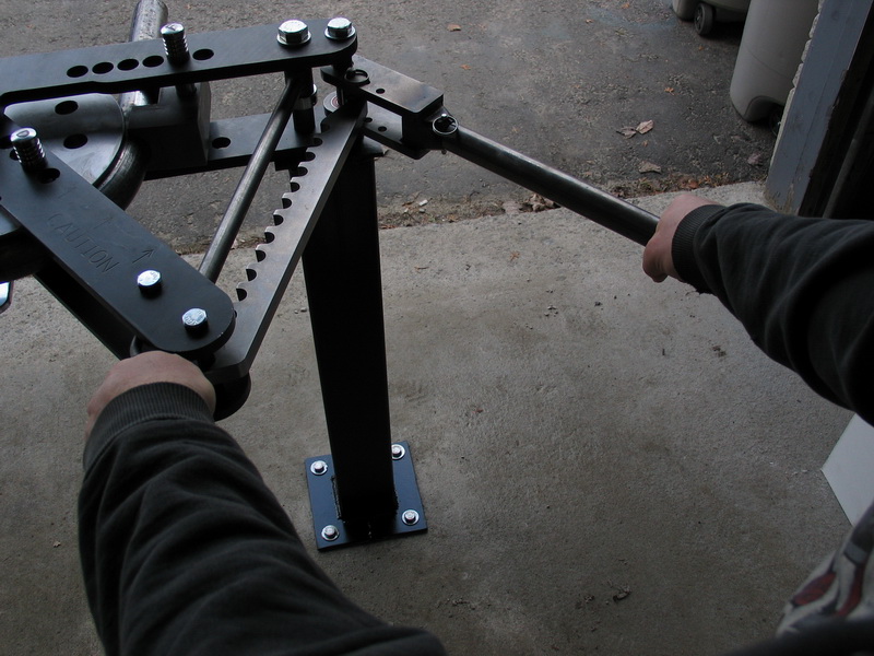
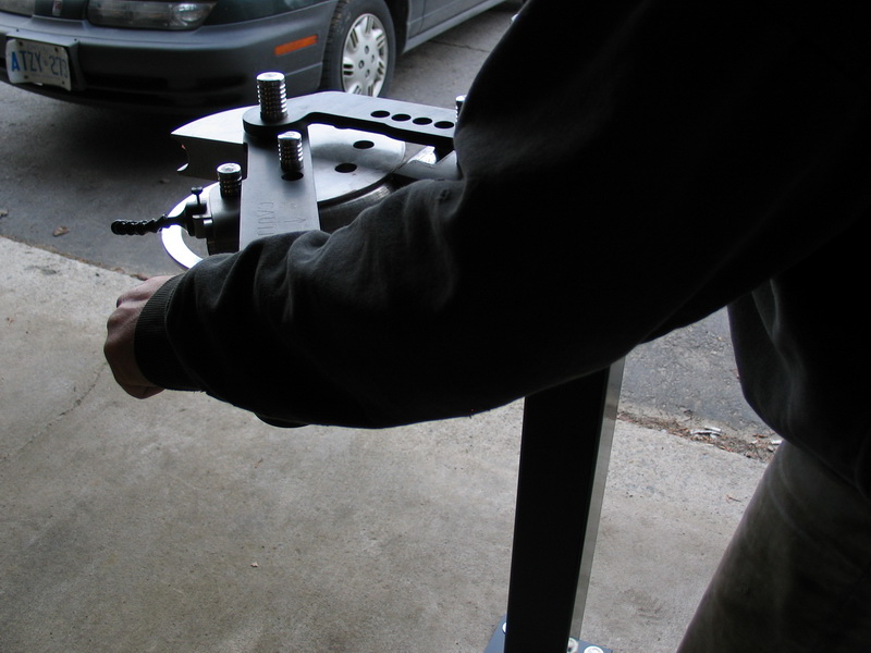
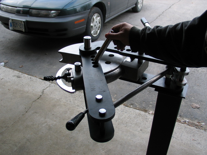
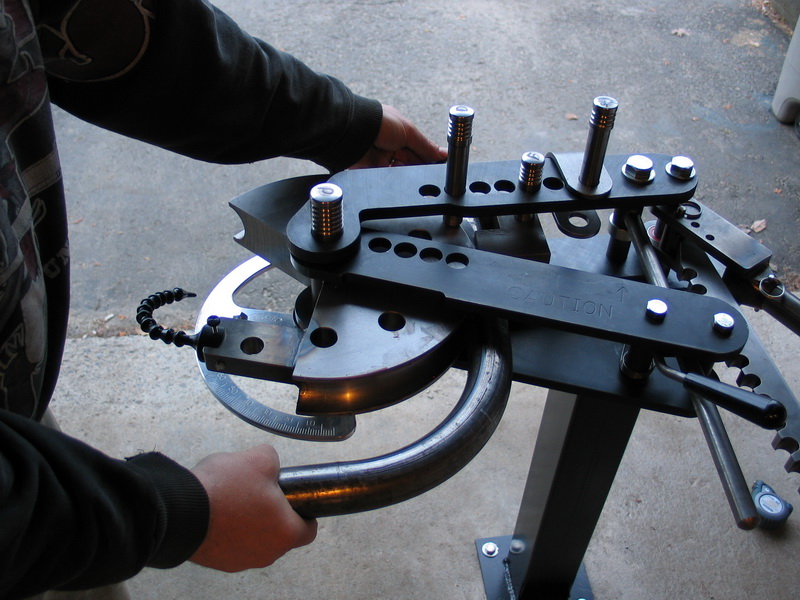
Pull on the handle to advance the drive rack and open the pivot arms. At the end of the pull, disengage the drive rack from the drive sleeve, return the handle to the starting position, engage the next tooth, and pull again. Repeat as necessary. Don't forget to check the degree pointer as you go, and to account for spring back before you finish the bend. |
||||||||||||||||||||||||||||||||||||||||||||||||||||||||||||||||||||||||||||||||||||||||||||||||||||||||||||||||||||||||||||||||||||||||||||||||||||||||||||||||||||||||||||||||||||||||||||||||||||||||||||||||||||||||||||||||||||||||||||||||||||||||||||||||||||||||||||||||||||||||||||||||||||||||||||||||||||||||||||||||||||||||||||
 |
If you are bending to more than about 55°, you will reach the end of the drive rack before you have finished the bend. The exact number of degrees you get from "one rack" will depend on the lever selection position - max leverage, max speed, or the middle position. |
||||||||||||||||||||||||||||||||||||||||||||||||||||||||||||||||||||||||||||||||||||||||||||||||||||||||||||||||||||||||||||||||||||||||||||||||||||||||||||||||||||||||||||||||||||||||||||||||||||||||||||||||||||||||||||||||||||||||||||||||||||||||||||||||||||||||||||||||||||||||||||||||||||||||||||||||||||||||||||||||||||||||||||
 |
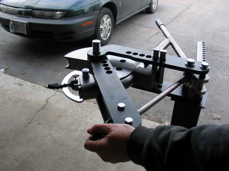
To continue bending, use the handle to put slight pressure on the pivot arms so that you can release the anti-spring-back release lever. | ||||||||||||||||||||||||||||||||||||||||||||||||||||||||||||||||||||||||||||||||||||||||||||||||||||||||||||||||||||||||||||||||||||||||||||||||||||||||||||||||||||||||||||||||||||||||||||||||||||||||||||||||||||||||||||||||||||||||||||||||||||||||||||||||||||||||||||||||||||||||||||||||||||||||||||||||||||||||||||||||||||||||||||
 |
Put some pressure on the anti-spring-back release handle and slightly close the pivot arms to take the pressure off the drive pin... | ||||||||||||||||||||||||||||||||||||||||||||||||||||||||||||||||||||||||||||||||||||||||||||||||||||||||||||||||||||||||||||||||||||||||||||||||||||||||||||||||||||||||||||||||||||||||||||||||||||||||||||||||||||||||||||||||||||||||||||||||||||||||||||||||||||||||||||||||||||||||||||||||||||||||||||||||||||||||||||||||||||||||||||
 |
...disengage the drive rack and swing it and the handle out of the way... | ||||||||||||||||||||||||||||||||||||||||||||||||||||||||||||||||||||||||||||||||||||||||||||||||||||||||||||||||||||||||||||||||||||||||||||||||||||||||||||||||||||||||||||||||||||||||||||||||||||||||||||||||||||||||||||||||||||||||||||||||||||||||||||||||||||||||||||||||||||||||||||||||||||||||||||||||||||||||||||||||||||||||||||
 |
... and remove the drive pin... | ||||||||||||||||||||||||||||||||||||||||||||||||||||||||||||||||||||||||||||||||||||||||||||||||||||||||||||||||||||||||||||||||||||||||||||||||||||||||||||||||||||||||||||||||||||||||||||||||||||||||||||||||||||||||||||||||||||||||||||||||||||||||||||||||||||||||||||||||||||||||||||||||||||||||||||||||||||||||||||||||||||||||||||
 |
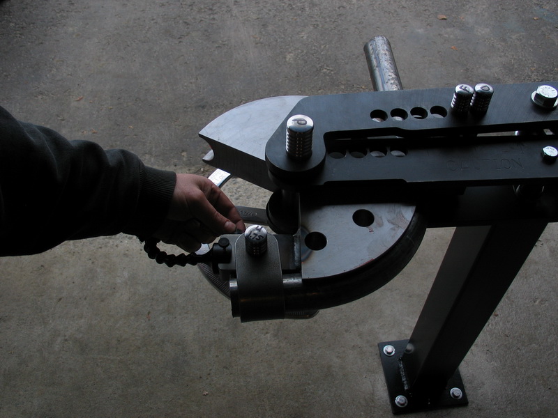
Press the anti-spring-back release handle towards the main arms and, while holding slight pressure on it... |
||||||||||||||||||||||||||||||||||||||||||||||||||||||||||||||||||||||||||||||||||||||||||||||||||||||||||||||||||||||||||||||||||||||||||||||||||||||||||||||||||||||||||||||||||||||||||||||||||||||||||||||||||||||||||||||||||||||||||||||||||||||||||||||||||||||||||||||||||||||||||||||||||||||||||||||||||||||||||||||||||||||||||||
 |
...swing the pivot arms back towards the main arms... | ||||||||||||||||||||||||||||||||||||||||||||||||||||||||||||||||||||||||||||||||||||||||||||||||||||||||||||||||||||||||||||||||||||||||||||||||||||||||||||||||||||||||||||||||||||||||||||||||||||||||||||||||||||||||||||||||||||||||||||||||||||||||||||||||||||||||||||||||||||||||||||||||||||||||||||||||||||||||||||||||||||||||||||
 |
...until the drive holes in the pivot arms line up with the next drive hole in the die. | ||||||||||||||||||||||||||||||||||||||||||||||||||||||||||||||||||||||||||||||||||||||||||||||||||||||||||||||||||||||||||||||||||||||||||||||||||||||||||||||||||||||||||||||||||||||||||||||||||||||||||||||||||||||||||||||||||||||||||||||||||||||||||||||||||||||||||||||||||||||||||||||||||||||||||||||||||||||||||||||||||||||||||||
 |
Reinsert the drive pin... | ||||||||||||||||||||||||||||||||||||||||||||||||||||||||||||||||||||||||||||||||||||||||||||||||||||||||||||||||||||||||||||||||||||||||||||||||||||||||||||||||||||||||||||||||||||||||||||||||||||||||||||||||||||||||||||||||||||||||||||||||||||||||||||||||||||||||||||||||||||||||||||||||||||||||||||||||||||||||||||||||||||||||||||
 |
...re-engage the drive rack... | ||||||||||||||||||||||||||||||||||||||||||||||||||||||||||||||||||||||||||||||||||||||||||||||||||||||||||||||||||||||||||||||||||||||||||||||||||||||||||||||||||||||||||||||||||||||||||||||||||||||||||||||||||||||||||||||||||||||||||||||||||||||||||||||||||||||||||||||||||||||||||||||||||||||||||||||||||||||||||||||||||||||||||||
 |
(it will start further down the rack teeth, of course) | ||||||||||||||||||||||||||||||||||||||||||||||||||||||||||||||||||||||||||||||||||||||||||||||||||||||||||||||||||||||||||||||||||||||||||||||||||||||||||||||||||||||||||||||||||||||||||||||||||||||||||||||||||||||||||||||||||||||||||||||||||||||||||||||||||||||||||||||||||||||||||||||||||||||||||||||||||||||||||||||||||||||||||||
 |
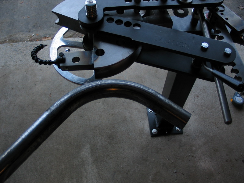
... and keep pulling the handle until you reach the desired bend angle... | ||||||||||||||||||||||||||||||||||||||||||||||||||||||||||||||||||||||||||||||||||||||||||||||||||||||||||||||||||||||||||||||||||||||||||||||||||||||||||||||||||||||||||||||||||||||||||||||||||||||||||||||||||||||||||||||||||||||||||||||||||||||||||||||||||||||||||||||||||||||||||||||||||||||||||||||||||||||||||||||||||||||||||||
 |
... as indicated on the degree ring. Don't forget to account for spring back before stopping the bend. |
||||||||||||||||||||||||||||||||||||||||||||||||||||||||||||||||||||||||||||||||||||||||||||||||||||||||||||||||||||||||||||||||||||||||||||||||||||||||||||||||||||||||||||||||||||||||||||||||||||||||||||||||||||||||||||||||||||||||||||||||||||||||||||||||||||||||||||||||||||||||||||||||||||||||||||||||||||||||||||||||||||||||||||
 |
When the bend is finished, remove the drive pin and return the pivot arms to the closed position, using the same method as described above. | ||||||||||||||||||||||||||||||||||||||||||||||||||||||||||||||||||||||||||||||||||||||||||||||||||||||||||||||||||||||||||||||||||||||||||||||||||||||||||||||||||||||||||||||||||||||||||||||||||||||||||||||||||||||||||||||||||||||||||||||||||||||||||||||||||||||||||||||||||||||||||||||||||||||||||||||||||||||||||||||||||||||||||||
 |
Loosen the tensioner bolt... | ||||||||||||||||||||||||||||||||||||||||||||||||||||||||||||||||||||||||||||||||||||||||||||||||||||||||||||||||||||||||||||||||||||||||||||||||||||||||||||||||||||||||||||||||||||||||||||||||||||||||||||||||||||||||||||||||||||||||||||||||||||||||||||||||||||||||||||||||||||||||||||||||||||||||||||||||||||||||||||||||||||||||||||
 |
... and remove the U-strap pin... | ||||||||||||||||||||||||||||||||||||||||||||||||||||||||||||||||||||||||||||||||||||||||||||||||||||||||||||||||||||||||||||||||||||||||||||||||||||||||||||||||||||||||||||||||||||||||||||||||||||||||||||||||||||||||||||||||||||||||||||||||||||||||||||||||||||||||||||||||||||||||||||||||||||||||||||||||||||||||||||||||||||||||||||
 |
...and the U-strap. | ||||||||||||||||||||||||||||||||||||||||||||||||||||||||||||||||||||||||||||||||||||||||||||||||||||||||||||||||||||||||||||||||||||||||||||||||||||||||||||||||||||||||||||||||||||||||||||||||||||||||||||||||||||||||||||||||||||||||||||||||||||||||||||||||||||||||||||||||||||||||||||||||||||||||||||||||||||||||||||||||||||||||||||
 |
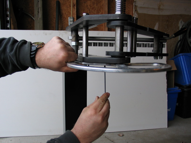
Give the tube a firm bump or grab the back end of it and waggle it, to release it from the die and follower-block. | ||||||||||||||||||||||||||||||||||||||||||||||||||||||||||||||||||||||||||||||||||||||||||||||||||||||||||||||||||||||||||||||||||||||||||||||||||||||||||||||||||||||||||||||||||||||||||||||||||||||||||||||||||||||||||||||||||||||||||||||||||||||||||||||||||||||||||||||||||||||||||||||||||||||||||||||||||||||||||||||||||||||||||||
 |
Slide the tube out from between the die and follower-block, towards the front. And you are done!
|
||||||||||||||||||||||||||||||||||||||||||||||||||||||||||||||||||||||||||||||||||||||||||||||||||||||||||||||||||||||||||||||||||||||||||||||||||||||||||||||||||||||||||||||||||||||||||||||||||||||||||||||||||||||||||||||||||||||||||||||||||||||||||||||||||||||||||||||||||||||||||||||||||||||||||||||||||||||||||||||||||||||||||||
Instructional VideoNow, if that wasn't all perfectly clear, here is a short video demonstrating the bending procedure from start to finish:
|
|||||||||||||||||||||||||||||||||||||||||||||||||||||||||||||||||||||||||||||||||||||||||||||||||||||||||||||||||||||||||||||||||||||||||||||||||||||||||||||||||||||||||||||||||||||||||||||||||||||||||||||||||||||||||||||||||||||||||||||||||||||||||||||||||||||||||||||||||||||||||||||||||||||||||||||||||||||||||||||||||||||||||||||
|
Sources: JMR Manufacturing, LLC P.O. Box 606 |
|