 |
Rebuild of Warn 8274 Winch By Bill "BillaVista" Ansell Photography: Bill Ansell |
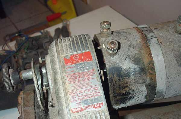
IntroductionI scored an older Warn 8274 8000lb winch for $200 and decided to completely strip and rebuild it. This article details how.
|
 |
A lot of people have contacted me and asked what the process was that I used to clean up the winch - apparently I did a pretty good job! What I did was as follows:
That's it. Really, I just took my time and enjoyed the process. Good luck! |
|
 |
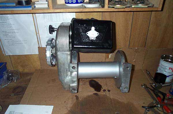
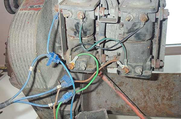
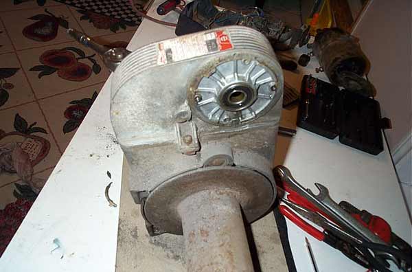
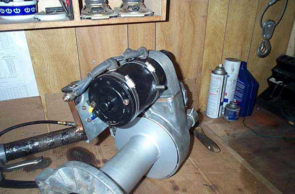
This is what my $200 bought! Note the hacked wiring as the remote was lost. The cable was also missing. |
 |
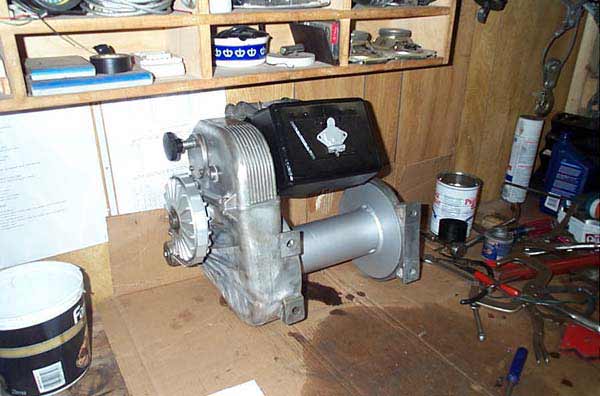
Top view. |
 |
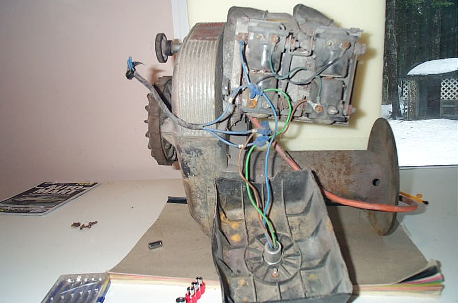
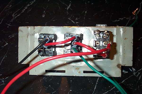
Mine was an older model that uses the 4 basic "starter style" solenoids. I'm actually happy about this as it's very easy to understand the wiring (and hence jumper or bypass it if required). |
 |
The newer models (with the remote plug-in on the side of the solenoid pack cover as opposed to the front) use a different solenoid style and a different wiring scheme. I don't know if the starter solenoids will work in those. |
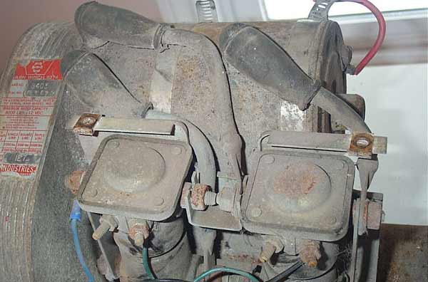 |
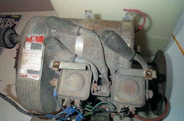
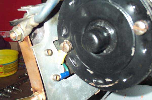
As you can see - all the electrics needed a damn good cleaning. In fact - I decided to totally strip and clean the whole thing. |
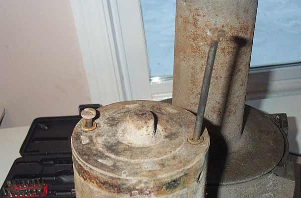 |
The motor mounts to the winch, and its own end cap is held on by, these 2 long screws. |
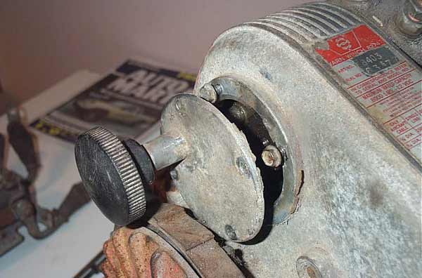 |
4 screws hold on the clutch. This is the knob device that allows free-spooling (pulled out) or connects the motor with the drum (pushed in, as shown). |
 |
Here's the motor being separated from the gearbox housing. |
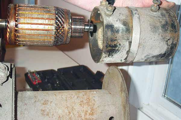 |
The motor housing comes off the armature. |
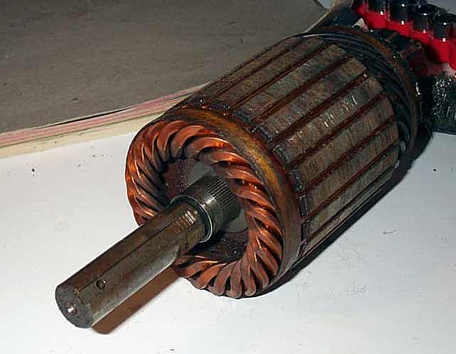 |
Here you can see the key way in the armature that indexes with the drive gear in the next pic. |
 |
Here's the key in the drive gear that indexes in the armature shaft. |
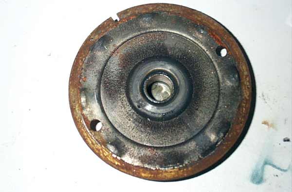 |
Here the end cap is off the motor. Note the little cut-out in the top left that indexes with the small nipple on the motor case. |
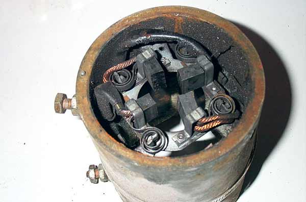 |
Inside the motor, end cap off. Showing the brushes. On the end of the case, on the left, is the little nipple that indexes the end cap. |
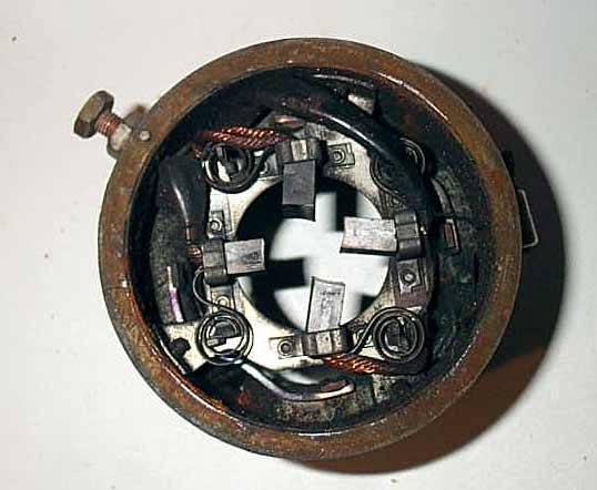 |
Another view of the motor brushes. |
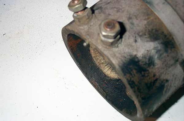 |
The motor case and electrical lugs. |
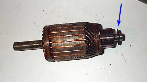 |
Make sure you don't lose this little washer on the end of the armature. |
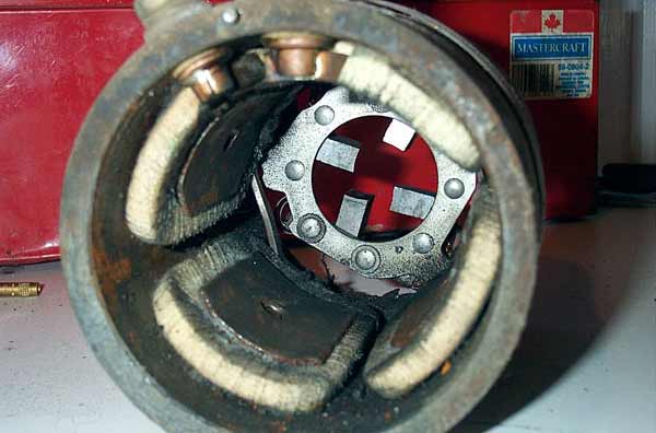 |
Inside the motor with the armature removed. |
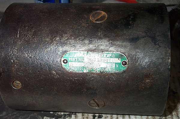 |
You can't quite make out the name on the motor in the pic, but interestingly it is not Warn! This is an original "earlier" motor. edit: Reader Mike Olstad kindly wrote in to inform me that the original motors were manufactured by the Prestolite company of Toledo, Ohio, USA, part number MBJ-401 |
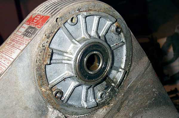 |
This is the top of the gear housing to which the motor attaches. You can clearly see the sealed bearing. Mine appeared fine, so I left it as it was. |
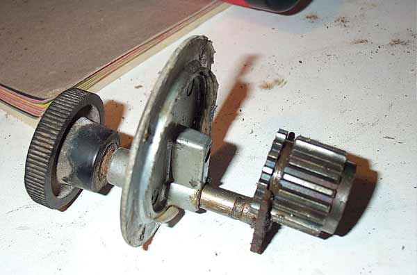 |
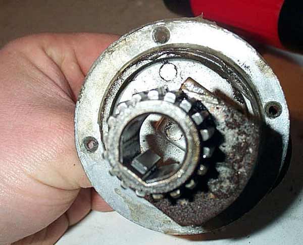
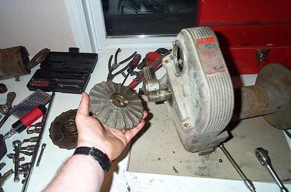
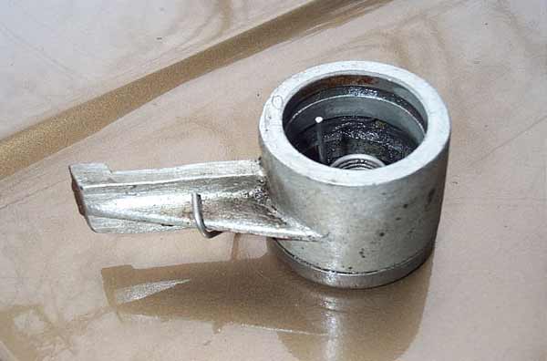
Here's the free spool clutch. The gear on the right side is the main drive gear, that you will recall from pic 11 above indexes directly on the motor armature. The black knob is what the operator uses to select power drive (in or out) or free spool...... |
 |
In is the position for power drive. This allows power out as well as power in of the cable. |
 |
Out disengages the motor from the drive train, and allows the cable to be free spooled out. Many an 8274 owner will tell you that the clutch rarely works, and the reason is because of corrosion between the shaft and the housing. |
 |
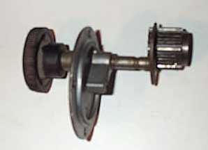
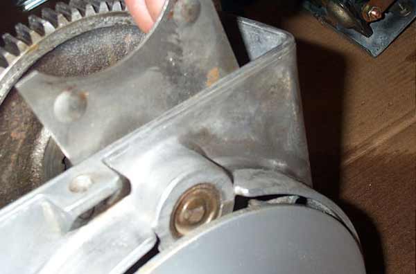
Here is what the clutch looks like engaged for power operation. |
 |
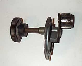
And this is what it looks like disengaged for free spool. |
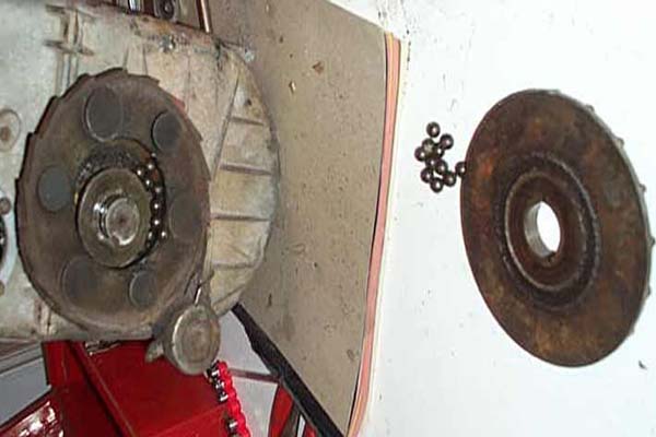 |
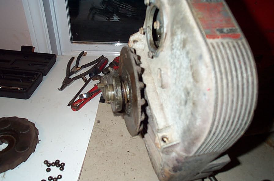
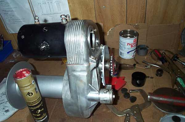
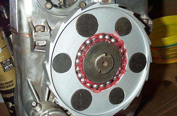
Next is disassembly of the brake assembly. When you remove the snap ring, the outside disc falls off under spring pressure, and all the ball bearings fall out! Update: Many readers have advised me that this brake disc can be a bear to remove. As my good buddy Mr. N. wrote "my outer brake disk did not pop off under spring pressure. In fact, it took two broken snap-ring pliers, one broken screw driver, and a 5-ton wheel puller to get the damn thing off!" So just be advised. Soaking the assembly in ATF or penetrating oil seems to help, but great force may be required. |
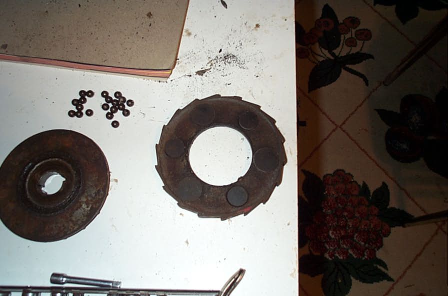 |
This is the outside brake disc, and the center ring with the little brake pucks of friction material. |
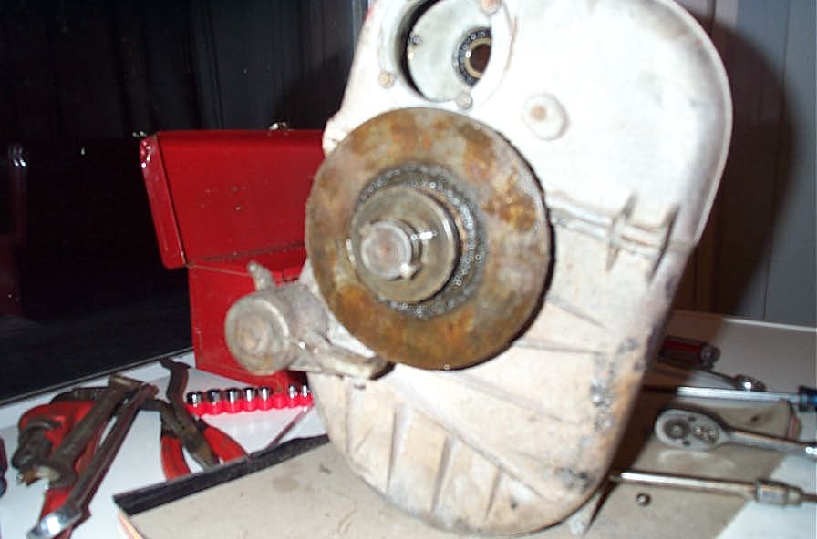 |
This is the inner brake disc still on the shaft. |
 |
|
 |
Inner brake disc coming off the shaft. |
 |
Here the brake and brake pawl are removed. |
 |
With the motor, brake, and clutch removed, you can separate the gearbox into two half's. There are 3 Allen head bolts with square nuts. 2 on the outside and .... |
 |
...one on the inside. |
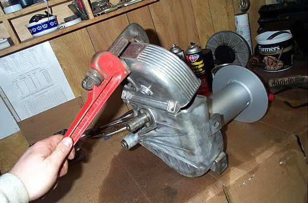 |
I used a pipe wrench to carefully lever the case halves apart, as the silicone sealer was old and set like concrete. |
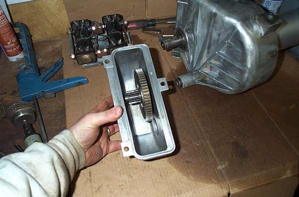 |
Here's the top half of the gearbox removed. |
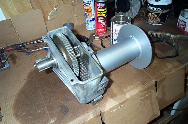 |
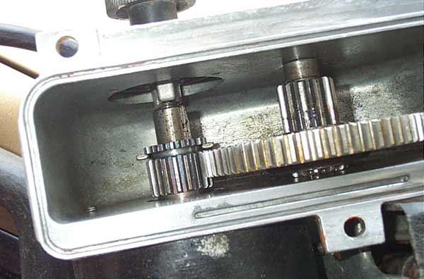
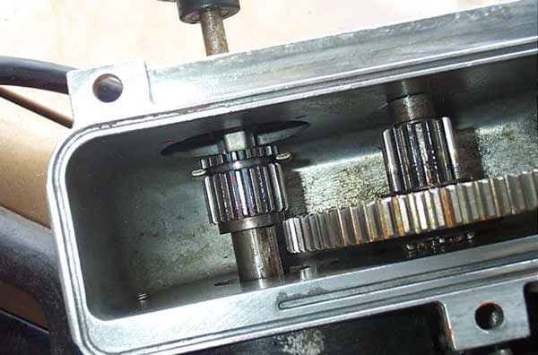
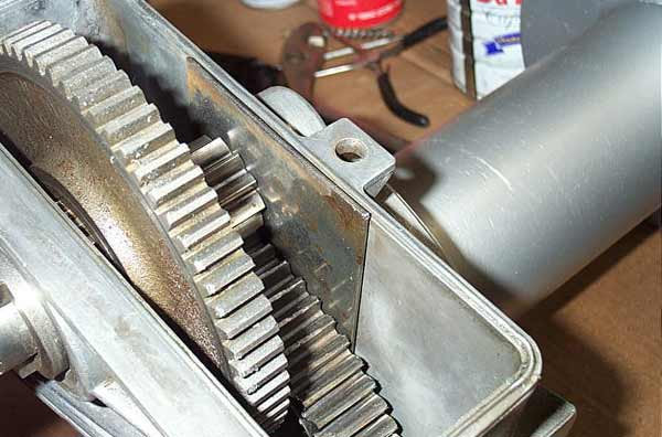
Here are the spur reduction gears in the bottom half of the gearbox. |
 |
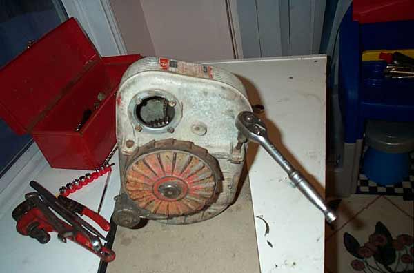
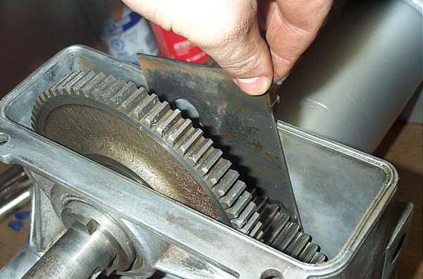
The next step in disassembly involves the lock plate shown here. |
 |
To remove the drum, you just need to pull the lock plate up, so it disengages the drum assembly. |
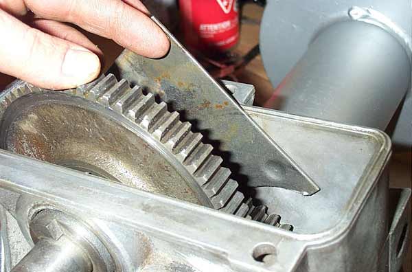 |
But if you actually want to remove the gears from the case (I didn't - didn't see any need) you tilt it to the side... |
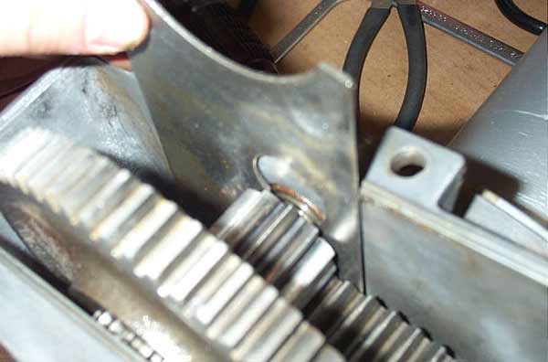 |
...invert it (note the larger hole in the plate)... |
 |
...then lower it so the larger hole is around the gear shaft, so that the shaft can be driven out (brass coloured round part). |
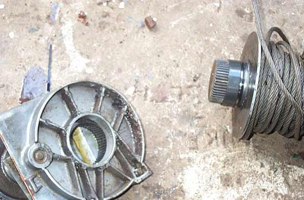 |
Here is the drum separated from the gearbox. |
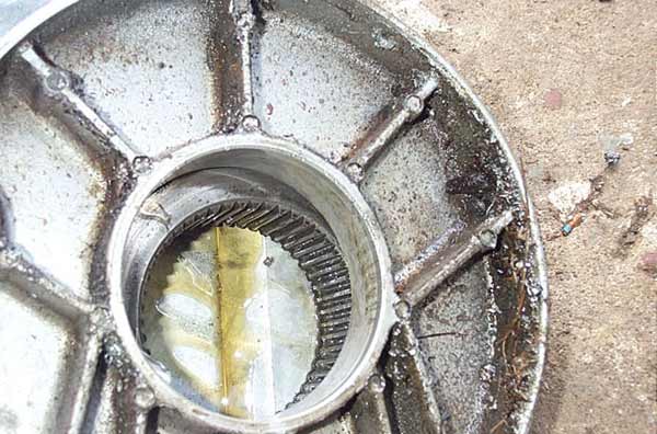 |
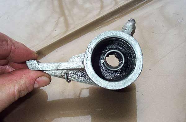
This is the gearbox, you can see the splined drive that drives the drum. |
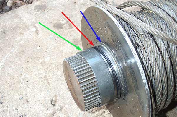 |
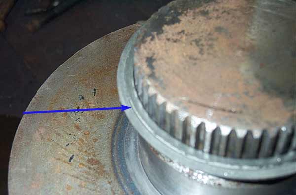
On the drum you will see the thrust washer (blue arrow), seal (red arrow) and bushing (green arrow). |
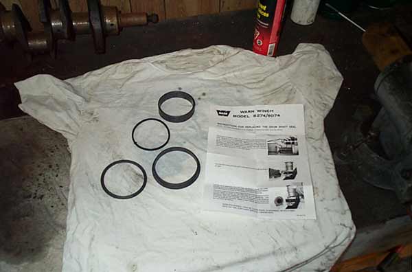 |
This is the Warn Part number 8680 "Service Kit - Lower Housing" It includes a new thrust washer, new seal, new bushing, new bushing for the other end of the drum, and a faded instruction sheet. |
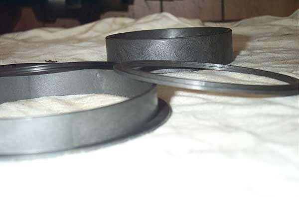 |
Close up of the replacement parts. You can see the lip on the thrust washer, which must go on first, same as the seal. In other words, they both go on the shaft the way they are sitting in this pic. |
 |
Like this. This is the thrust washer going on. |
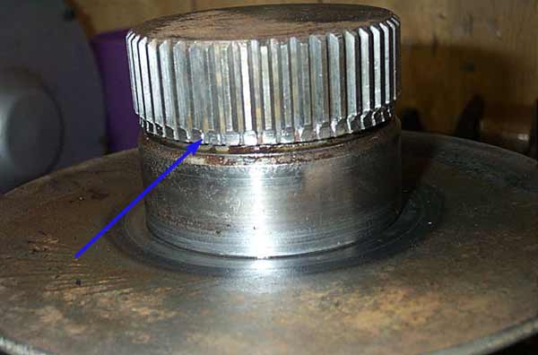 |
I don't know what the hell chewed the snot out of the splines - perhaps the lock plate improperly seated? Hasn't affected operation, which is good. |
 |
Here's the brake assembly being rebuilt. I re-used all my parts. |
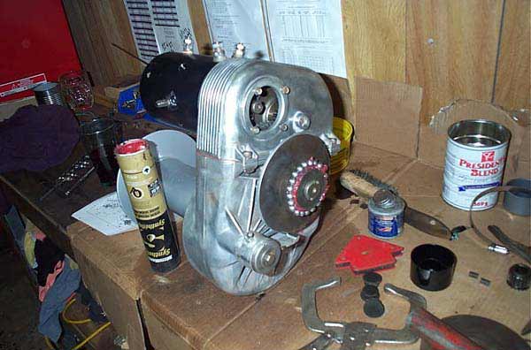 |
I used a sticky synthetic grease to stick the ball bearings on |
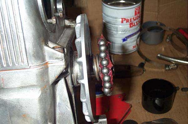 |
This was the trickiest part... |
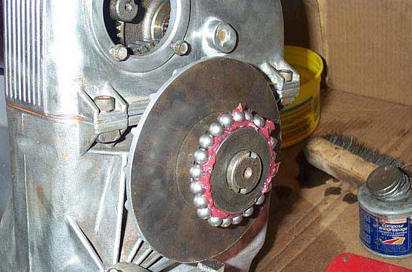 |
...as you have to keep all the balls in place... |
 |
...while sliding on the ring with the brake pucks. After this, you have to replace the outside wheel, and then compress the spring enough to install the snap ring. It's a bear. |
 |
Here's the brake pawl. |
edit: Reader Blake Christensen wrote in to share the method he used for re-assembling the brake assembly: "I just rebuilt a used 8274 after reading your very illustrative article. I wanted to tell you about how I solved the difficult problem of reassembling the spring loaded brake-clutch assembly. First of all, I did not feel comfortable using the sticky grease method you had described because this was a brake and any lubricant would negate the effect of the friction material. So instead I oriented the winch on the vice with the brake shaft vertical and began reassembling. When I had to put the 21 ball bearings back in, I used (4) rare earth magnets (the kind for picking up dropped bolts and stuff) to magnetize the steel ratchet plate that serves as the outer bearing race for the ball bearings. The balls stuck to the plate in a way that I could easily compress the whole assembly against it's spring - with a couple of vice grips - enough to place the retaining ring back on the end of the shaft." Thanks Blake! |
|
 |
It has a spring inside |
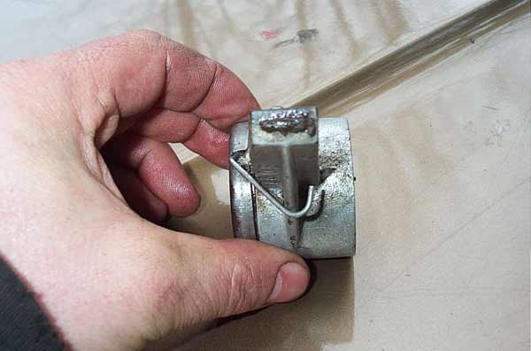 |
That hooks around outside. |
 |
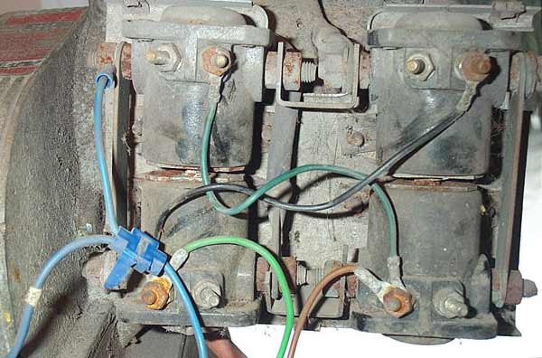
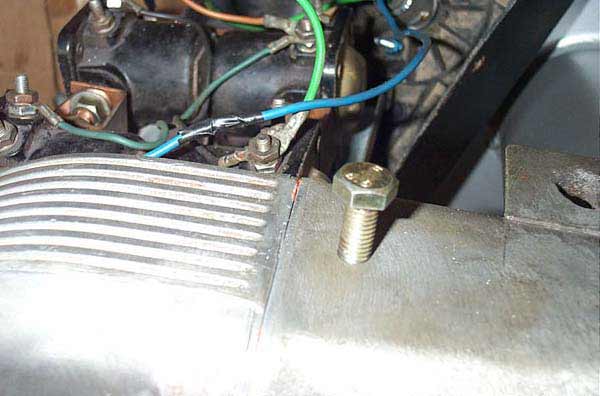
Because, in the older models like mine, the solenoid bracket is the ground for the solenoids, I added a small additional ground cable from the bracket to the motor housing |
 |
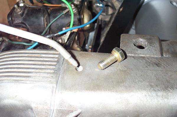
Also, in the older motors, the entire motor ground used a ring terminal under the head of one of the long bolts. This seemed a little inadequate to me, so I welded a bolt to the case to use as a big ground lug. |
 |
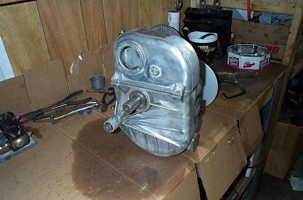
Next two pics just show it all rebuilt and cleaned up |
|
Looking much better! |
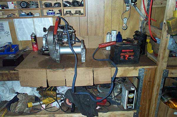 |
Final testing on the bench before installation. Took a battery and booster cables. Positive goes from battery (+) to the top left solenoid lug. Negative goes from battery (-) to the negative lug I welded on (motor case) |
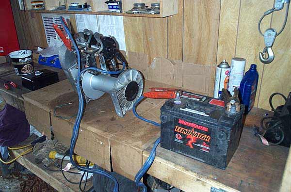 |
Testing setup |
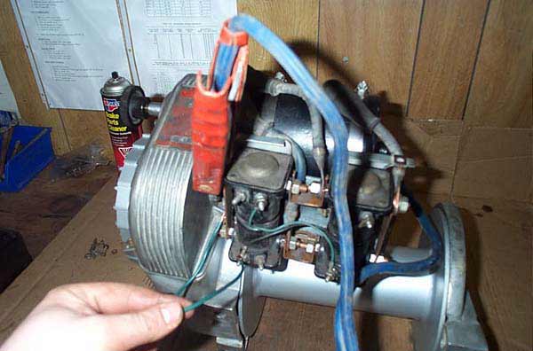 |
Then take a small jumper from the 12v+ to the S terminal of the lower left solenoid (green wire) and the winch should power in. |
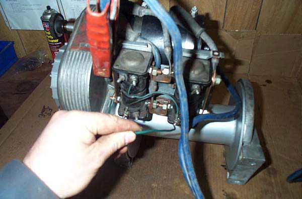 |
Then take a small jumper from the 12v+ to the S terminal of the lower right solenoid (brown wire) and the winch should power out. |
 |
I drilled and tapped a small hole to use as an oil filling spot, so I could easily add a little oil if I noticed any leaks, without having to split the gearbox case again. |
 |
Just big enough for the tip of an oil can |
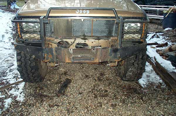 |
Of course, I had to mod the front bumper quite a bit to take the big 8274. The mount is a piece of 3/8" 7"x4" angle |
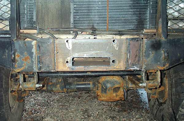 |
It's critical to mount the winch good and square, and I suck at laying out holes in precision, so to give myself room to adjust, I hogged out the left side holes with a torch! |
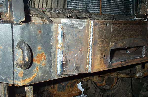 |
This was kind of an interesting comparison between "vertical up" and "vertical down" MIG welding. The weld on the left is vertical down - looks nicer, but is not the proper way. On the right is two passes with vertical up. |
 |
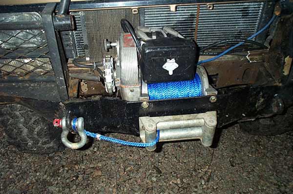
It looks pretty good in there...and is just about to get used here! |
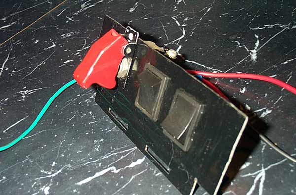 |
Here's the extremely sexy in-cab winch control I made. It has a guarded switch for power on / off, and two spring loaded momentary switches - one for cable in, and one for cable out. |
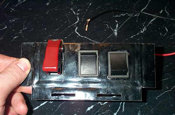 |
It's kind of clever how I reversed the two black control switches, so that they can be distinguished even without labels or in the dark. |
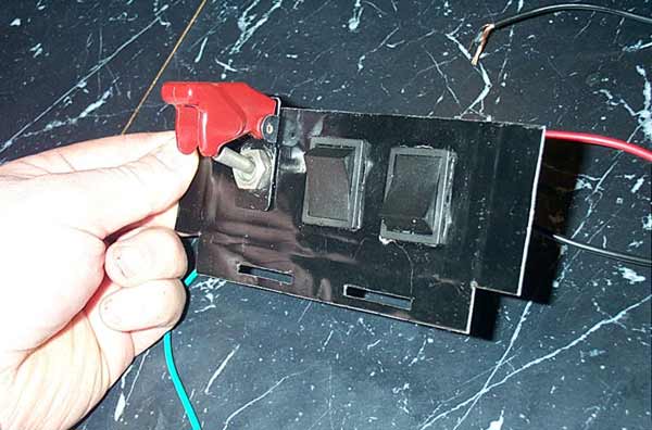 |
Here the guard is raised and the master switch closed, providing 12v+ to the operating switches. To stop all winch operation, one need only close the cover, opening the switch. |
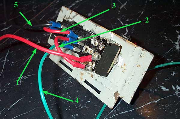 |
Here's how it works:
Fused 12V+ from battery comes in on #1. When the cover is raised and the master switch closed, 12v+ flows along #2 to the first (winch cable in) switch. If that first (winch in) switch remains un-activated, 12v+ flows to the last (winch cable out) switch along #3. However, when the winch in switch is activated, 12v+ is cut off from the winch out switch. In this manner, the winch cannot be simultaneously powered in and out. |
When the winch in switch is pressed, power flows to the appropriate solenoid (S terminal of lower left solenoid) along green wire #4. When the winch out switch is pressed, power flows to the appropriate solenoid (S terminal of lower right solenoid) along brown wire #5. |
|
 |
Another look at the back. Check out the incredibly cool screw terminals on the aircraft covered switch! |
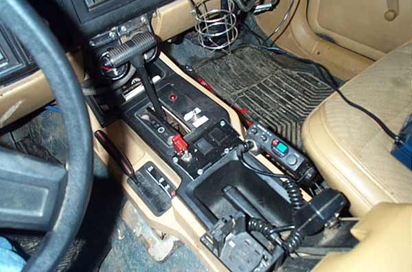 |
Here are the controls installed in the center console. |
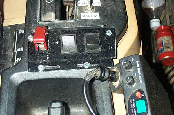 |
Close up installed, winch off. |
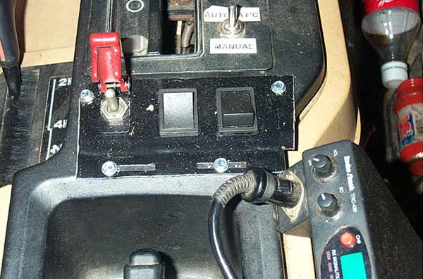 |
Close up, installed, guard up and power to winch controls. |
 |
When I got the whole thing done, it had cost me so little, I treated myself to 125' of Amsteel Blue UHMWPE "synthetic" rope. |
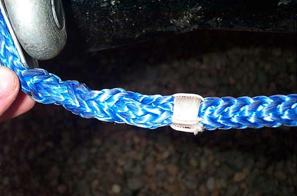 |
Check out the craftsmanship in that splice. I got my rope from a large
industrial / marine supplier in Dartmouth.
They sell a lot of this stuff to the offshore industry. |
Here are links to the Warn exploded diagrams and parts lists. There are 2 different diagrams, depending on your Serial number. Serial numbers 337844 and down. As far as where to buy the parts - I simply called Warn's 1-800-543-9276 number and asked for the name and number of the nearest authorized service center. There is an excellent web page by Warn where you can download the parts diagrams and lists for any winch (you will need your serial number) , as well as locate dealers. It is: http://www.warn.com/store/service_parts.jsp As far as what parts to replace on spec during a teardown and rebuild, if nothing looks worn, I would only replace the "service kit, lower housing" part number 8680 (all serial numbers). It includes 2 bushings, a seal, and thrust washer. These are the parts I installed in pics 43 to 47 above.The winch is lubricated with 6oz of NON-DETERGENT 30wt motor oil WINCH WIRING and TESTINGI received a lot of e-mails about how the winch is supposed to be wired, how it operates electrically, and how to test the motor and solenoids, so I've added this section to address those questions. My nomenclature / naming conventions |
|
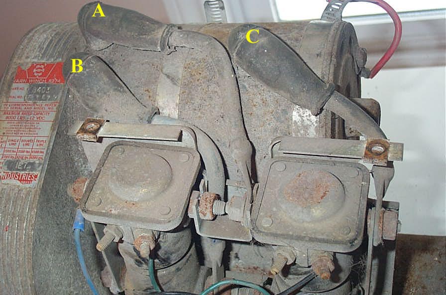 |
Motor has 3 terminals, I have labelled from left to right A, B, and C. |
Motor case is grounded directly to (-) terminal of battery I use the term “12v+ signal” to refer to the small current 12v+ that is transferred from the winch power input terminal, through the switch or remote, and back to the solenoids to activate them I use the term “12v+ power” to refer to the high current 12v+ that actually powers the winch. Solenoids have 2 studs (the large threaded studs on the sides), and a small terminal, called the S terminal (some have 2 small terminals, but for our discussion, only the small “S” terminal is used). They are simple electronically activated switches. When you apply a 12v+ signal to the small S terminal, the switch inside closes, connecting the 2 large studs together. This understanding is key to testing and troubleshooting your winch. NOTE: Technically, this is true only for SPNO (single pole, normally open) solenoids, such as those used in older 8274’s (with the 3 pin remote connector) Warn part number 2040, and Ford “round style” starter solenoids. Also note, the solenoids themselves ground through their cases, and in the case of the 8274 to the metal solenoid bracket, and through it to the motor housing itself. Make sure all these connections are clean and tight. For extra insurance, I added a small ground jumper from the solenoid bracket to the motor housing (ring terminal under the head of one of the long motor housing bolts), so I wouldn’t have to rely on only the large hose clamps holding the solenoid bracket to the motor case for the solenoid ground. |
|
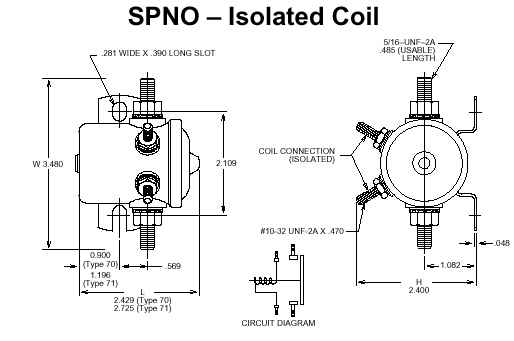 |
Here is a solenoid: Warn solenoids (pn 2040 for old style and 28396 for new style) |
You can test your solenoids as follows: 1) Remove solenoid 2) Check to be sure the contact disc inside the solenoid is not stuck, Connect an ohm-meter between the 2 large studs, the meter should show an open circuit or infinite resistance reading. 3) Connect a jumper wire from the solenoid case to the (-) term of your battery 4) Connect a jumper wire from the small solenoid “S” terminal to the (+) terminal of your battery. 5) You should hear the solenoid “click”, it is now “energized” and the 2 studs are connected together. 6) Connect an ohm-meter across the 2 large studs while the solenoid is energized, the resistance should read 0 ohms. 7) Remove the jumpers from the solenoid. 8) With the ohmmeter set at the lowest scale, connect the ohmmeter leads to the “S” terminal and the solenoid case. The reading should be between 3.4 and 4.5 ohms. If you get a reading lower than 3.4 ohms, the solenoid has shorted windings. If a reading higher than 4.5 ohms is observed, the solenoid either has a bad internal winding connection or corrosion in the windings. This occurs if the solenoid has been on the vehicle for along time. |
|
|