 |
The 14-Bolt Bible By Bill "BillaVista" Ansell |
IntroductionThis article is a compilation of information and and specs relating to the venerable GM Corporate 14 Bolt full-floating rear axle - also referred to as the 10.5" (after the size of the ring gear in inches) or just simply the "14b" for short. There are other 14b axles out there - a 9.5" ring gear semi-float for one, and even a 11.5" ring gear full-float version. This article is not about them. |
 |
US Military CUCV Manual - 14-Bolt Excerpts |
|
 |
A range of US Military trucks over the years have been equipped with the 14-Bolt rear axle, including the Commercial Utility Cargo Vehicle or "CUCV". The US Military also produces, free of copyright restrictions, manuals for these vehicles. Normally, the manuals come in large volume sets comprising hundreds of pages covering every aspect of the vehicle. So that you do not have to wade through all this data to find information on the 14-Bolt rear axle, I extracted only the relevant information and compiled it all into a single 14-Bolt Manual in .pdf format. |
||||||||||||||||||||||||||||||||||||||||||||||||||||||||||||||||||||||||||||||||||||||||||||||||||||||||||||||||||||||||||||||||||||||||||||||||||||||||||||||||||||||||||||||||||||||||||||||||||||||||||||||||||||||||||||||||||||||||||||||||||||||||||||||||||||||||||||||||||||||||||||||||||||||||||||||||||||||||||||||||||||||||||||||||||||||||||||||||||||||||||||||||||||||||||||||||||||||||||||||||||||||||||||||||||||||||||||||||||||||||||||||||||||
Identification, Data, and Specs |
|||||||||||||||||||||||||||||||||||||||||||||||||||||||||||||||||||||||||||||||||||||||||||||||||||||||||||||||||||||||||||||||||||||||||||||||||||||||||||||||||||||||||||||||||||||||||||||||||||||||||||||||||||||||||||||||||||||||||||||||||||||||||||||||||||||||||||||||||||||||||||||||||||||||||||||||||||||||||||||||||||||||||||||||||||||||||||||||||||||||||||||||||||||||||||||||||||||||||||||||||||||||||||||||||||||||||||||||||||||||||||||||||||||
 |
The 14bolt is found in a huge number of GM 4x4 pickup trucks and vans, 3/4 and 1 ton, from the 70's right through until at least the 2000's. You can find it in:
As well as a whole lot more cab and chassis trucks, delivery vans, etc. |
||||||||||||||||||||||||||||||||||||||||||||||||||||||||||||||||||||||||||||||||||||||||||||||||||||||||||||||||||||||||||||||||||||||||||||||||||||||||||||||||||||||||||||||||||||||||||||||||||||||||||||||||||||||||||||||||||||||||||||||||||||||||||||||||||||||||||||||||||||||||||||||||||||||||||||||||||||||||||||||||||||||||||||||||||||||||||||||||||||||||||||||||||||||||||||||||||||||||||||||||||||||||||||||||||||||||||||||||||||||||||||||||||||
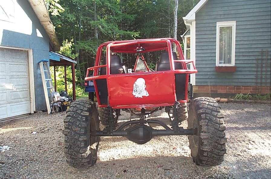 |
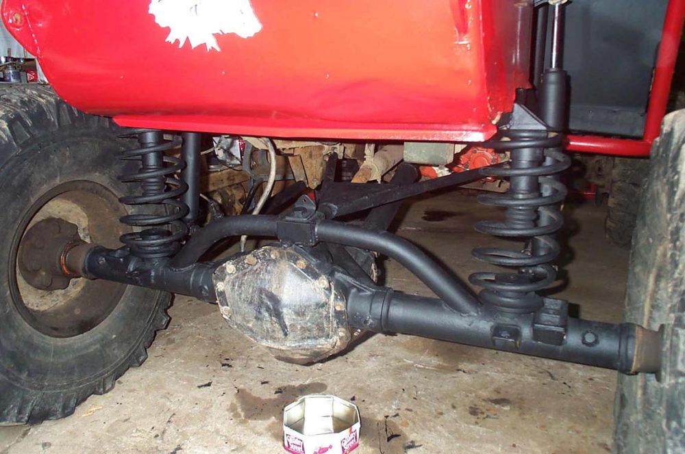
This is what it looks like in my rock buggy. | ||||||||||||||||||||||||||||||||||||||||||||||||||||||||||||||||||||||||||||||||||||||||||||||||||||||||||||||||||||||||||||||||||||||||||||||||||||||||||||||||||||||||||||||||||||||||||||||||||||||||||||||||||||||||||||||||||||||||||||||||||||||||||||||||||||||||||||||||||||||||||||||||||||||||||||||||||||||||||||||||||||||||||||||||||||||||||||||||||||||||||||||||||||||||||||||||||||||||||||||||||||||||||||||||||||||||||||||||||||||||||||||||||||
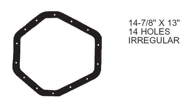 |
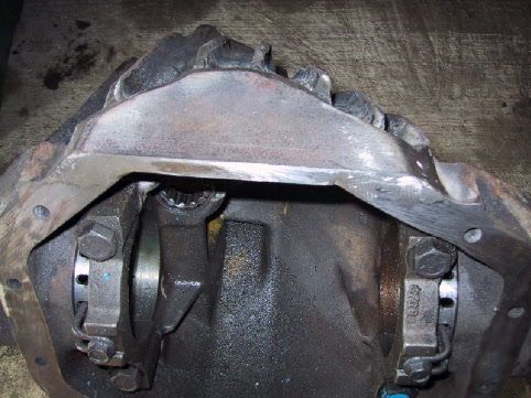
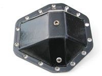
It is most easily distinguished by its huge, uniquely shaped diff cover that is, of course, held on with 14 bolts. | ||||||||||||||||||||||||||||||||||||||||||||||||||||||||||||||||||||||||||||||||||||||||||||||||||||||||||||||||||||||||||||||||||||||||||||||||||||||||||||||||||||||||||||||||||||||||||||||||||||||||||||||||||||||||||||||||||||||||||||||||||||||||||||||||||||||||||||||||||||||||||||||||||||||||||||||||||||||||||||||||||||||||||||||||||||||||||||||||||||||||||||||||||||||||||||||||||||||||||||||||||||||||||||||||||||||||||||||||||||||||||||||||||||
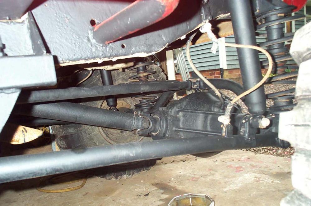 |
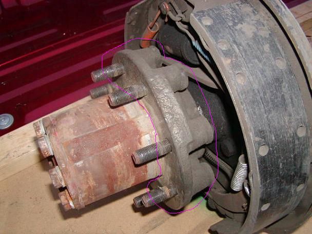
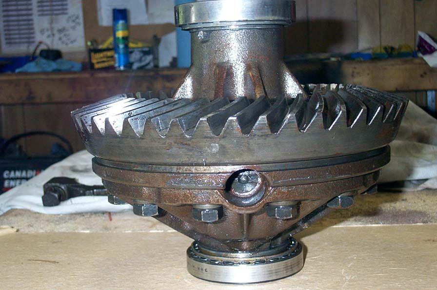
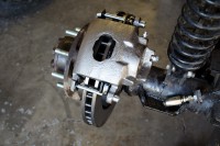
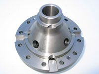
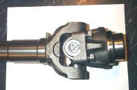
It is also fairly easily distinguished from other 1 ton full-float rear axles by the removable pinion support, that can be clearly seen just behind the pinion yoke in this picture. | ||||||||||||||||||||||||||||||||||||||||||||||||||||||||||||||||||||||||||||||||||||||||||||||||||||||||||||||||||||||||||||||||||||||||||||||||||||||||||||||||||||||||||||||||||||||||||||||||||||||||||||||||||||||||||||||||||||||||||||||||||||||||||||||||||||||||||||||||||||||||||||||||||||||||||||||||||||||||||||||||||||||||||||||||||||||||||||||||||||||||||||||||||||||||||||||||||||||||||||||||||||||||||||||||||||||||||||||||||||||||||||||||||||
 |
Being a full-float (FF) axle means it has full-floating wheel hubs and axle shafts. I simply love full-float axles, and would never go back to running anything but a FF axle, for the following very good reasons:
|
||||||||||||||||||||||||||||||||||||||||||||||||||||||||||||||||||||||||||||||||||||||||||||||||||||||||||||||||||||||||||||||||||||||||||||||||||||||||||||||||||||||||||||||||||||||||||||||||||||||||||||||||||||||||||||||||||||||||||||||||||||||||||||||||||||||||||||||||||||||||||||||||||||||||||||||||||||||||||||||||||||||||||||||||||||||||||||||||||||||||||||||||||||||||||||||||||||||||||||||||||||||||||||||||||||||||||||||||||||||||||||||||||||
Before we delve deeper into the 14bolt, let's just talk about why this is such an awesome axle. It has a number of distinct features / advantages:
Of course, there are drawbacks too:
Overall, I think they are a superb choice for a heavy duty off-road machine. The following quote from " H8Monday" (a rock crawling competitor and devout throttle-crazy maniac who runs a 14b behind a very healthy 5.0.) sums things up nicely:
Let's have a closer look at the beast. |
|||||||||||||||||||||||||||||||||||||||||||||||||||||||||||||||||||||||||||||||||||||||||||||||||||||||||||||||||||||||||||||||||||||||||||||||||||||||||||||||||||||||||||||||||||||||||||||||||||||||||||||||||||||||||||||||||||||||||||||||||||||||||||||||||||||||||||||||||||||||||||||||||||||||||||||||||||||||||||||||||||||||||||||||||||||||||||||||||||||||||||||||||||||||||||||||||||||||||||||||||||||||||||||||||||||||||||||||||||||||||||||||||||||
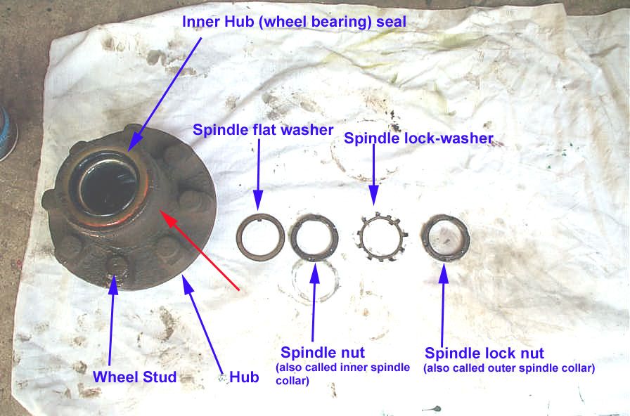 |
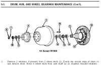
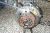
This pic is a closer look at the hub and wheel bearing / spindle hardware (with the brake disc or drum removed, looking at it from the back side [inside]). Note that the spindle threads are the same as for Dana 60 front and rear axles and Dana 70 rear axles. This means that all the different styles of spindle nuts (4 slot, 6 slot, hex, rounded hex) and lock washers can all be interchanged. Part numbers for the spindle hardware shown, from left to right are:
|
||||||||||||||||||||||||||||||||||||||||||||||||||||||||||||||||||||||||||||||||||||||||||||||||||||||||||||||||||||||||||||||||||||||||||||||||||||||||||||||||||||||||||||||||||||||||||||||||||||||||||||||||||||||||||||||||||||||||||||||||||||||||||||||||||||||||||||||||||||||||||||||||||||||||||||||||||||||||||||||||||||||||||||||||||||||||||||||||||||||||||||||||||||||||||||||||||||||||||||||||||||||||||||||||||||||||||||||||||||||||||||||||||||
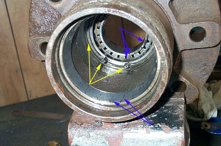 |
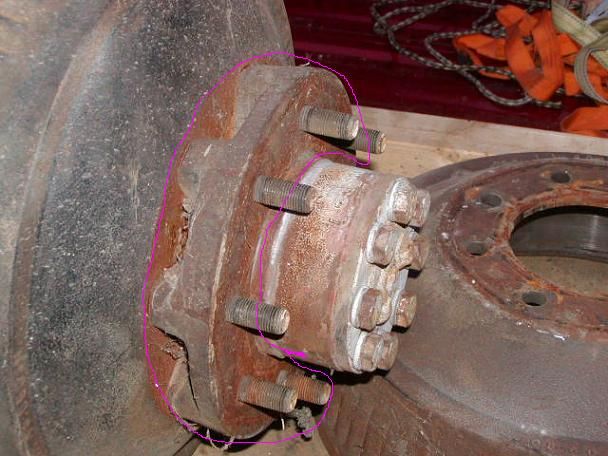
Watch out for this when you go to remove the wheel hub outer bearing and race. The bearing does not simply fall out of the end of the hub on most FF axles - its OD keeps it captive. Instead, a snap ring in the hub, accessible from the back of the hub (yellow arrows) needs to be removed so the wheel bearing can come out the back. Blue arrows show corrosion, indicating requirement for replacement bearings and races. |
||||||||||||||||||||||||||||||||||||||||||||||||||||||||||||||||||||||||||||||||||||||||||||||||||||||||||||||||||||||||||||||||||||||||||||||||||||||||||||||||||||||||||||||||||||||||||||||||||||||||||||||||||||||||||||||||||||||||||||||||||||||||||||||||||||||||||||||||||||||||||||||||||||||||||||||||||||||||||||||||||||||||||||||||||||||||||||||||||||||||||||||||||||||||||||||||||||||||||||||||||||||||||||||||||||||||||||||||||||||||||||||||||||
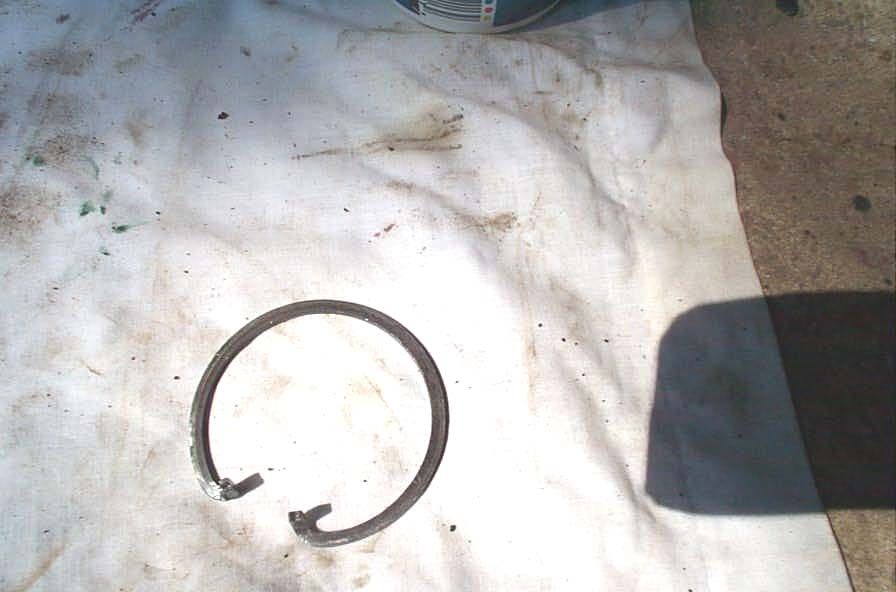 |
The snap ring mentioned above. | ||||||||||||||||||||||||||||||||||||||||||||||||||||||||||||||||||||||||||||||||||||||||||||||||||||||||||||||||||||||||||||||||||||||||||||||||||||||||||||||||||||||||||||||||||||||||||||||||||||||||||||||||||||||||||||||||||||||||||||||||||||||||||||||||||||||||||||||||||||||||||||||||||||||||||||||||||||||||||||||||||||||||||||||||||||||||||||||||||||||||||||||||||||||||||||||||||||||||||||||||||||||||||||||||||||||||||||||||||||||||||||||||||||
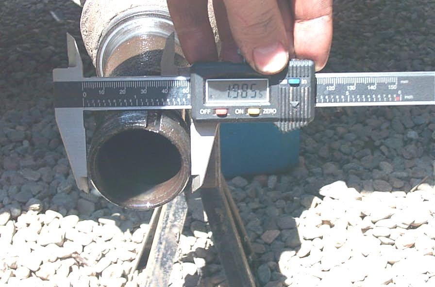 |
Spindle OD is approximately 1.985". | ||||||||||||||||||||||||||||||||||||||||||||||||||||||||||||||||||||||||||||||||||||||||||||||||||||||||||||||||||||||||||||||||||||||||||||||||||||||||||||||||||||||||||||||||||||||||||||||||||||||||||||||||||||||||||||||||||||||||||||||||||||||||||||||||||||||||||||||||||||||||||||||||||||||||||||||||||||||||||||||||||||||||||||||||||||||||||||||||||||||||||||||||||||||||||||||||||||||||||||||||||||||||||||||||||||||||||||||||||||||||||||||||||||
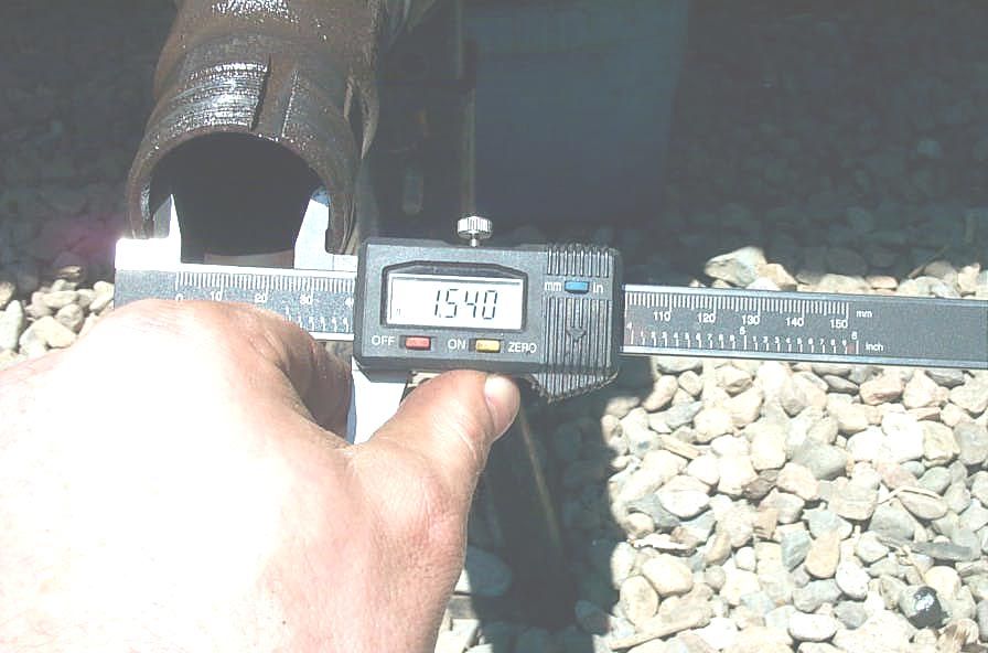 |
Spindle ID is approximately 1.540". | ||||||||||||||||||||||||||||||||||||||||||||||||||||||||||||||||||||||||||||||||||||||||||||||||||||||||||||||||||||||||||||||||||||||||||||||||||||||||||||||||||||||||||||||||||||||||||||||||||||||||||||||||||||||||||||||||||||||||||||||||||||||||||||||||||||||||||||||||||||||||||||||||||||||||||||||||||||||||||||||||||||||||||||||||||||||||||||||||||||||||||||||||||||||||||||||||||||||||||||||||||||||||||||||||||||||||||||||||||||||||||||||||||||
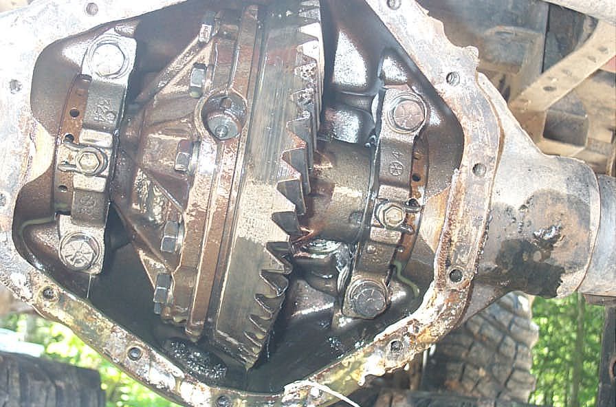 |
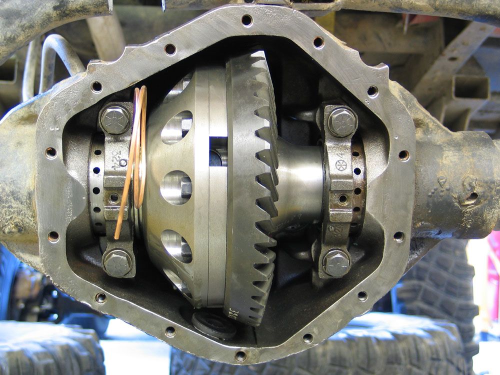
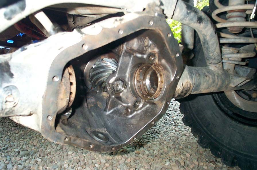
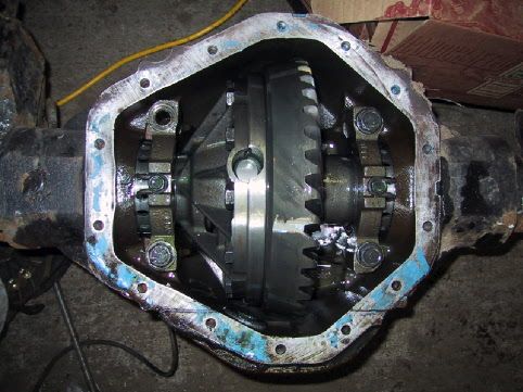
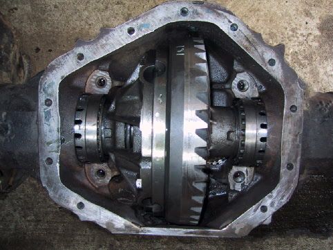
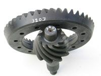
Take the cover off, and you discover the massive 2-piece carrier and 10.5" ring gear. | ||||||||||||||||||||||||||||||||||||||||||||||||||||||||||||||||||||||||||||||||||||||||||||||||||||||||||||||||||||||||||||||||||||||||||||||||||||||||||||||||||||||||||||||||||||||||||||||||||||||||||||||||||||||||||||||||||||||||||||||||||||||||||||||||||||||||||||||||||||||||||||||||||||||||||||||||||||||||||||||||||||||||||||||||||||||||||||||||||||||||||||||||||||||||||||||||||||||||||||||||||||||||||||||||||||||||||||||||||||||||||||||||||||
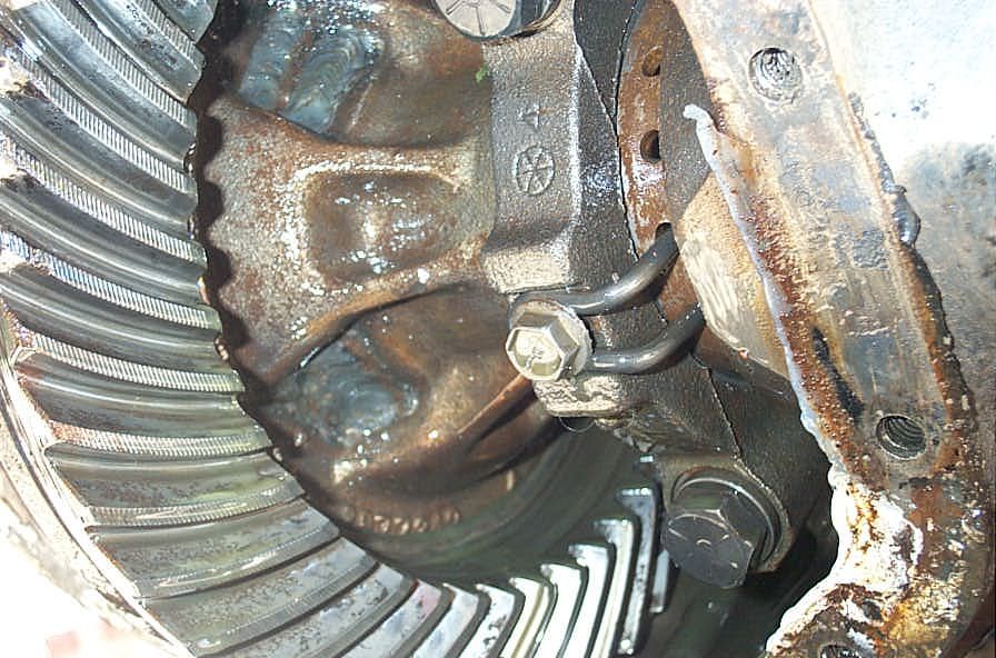 |
The bearing caps have small integrated locking devices that serve to lock the carrier preload adjusters into place. | ||||||||||||||||||||||||||||||||||||||||||||||||||||||||||||||||||||||||||||||||||||||||||||||||||||||||||||||||||||||||||||||||||||||||||||||||||||||||||||||||||||||||||||||||||||||||||||||||||||||||||||||||||||||||||||||||||||||||||||||||||||||||||||||||||||||||||||||||||||||||||||||||||||||||||||||||||||||||||||||||||||||||||||||||||||||||||||||||||||||||||||||||||||||||||||||||||||||||||||||||||||||||||||||||||||||||||||||||||||||||||||||||||||
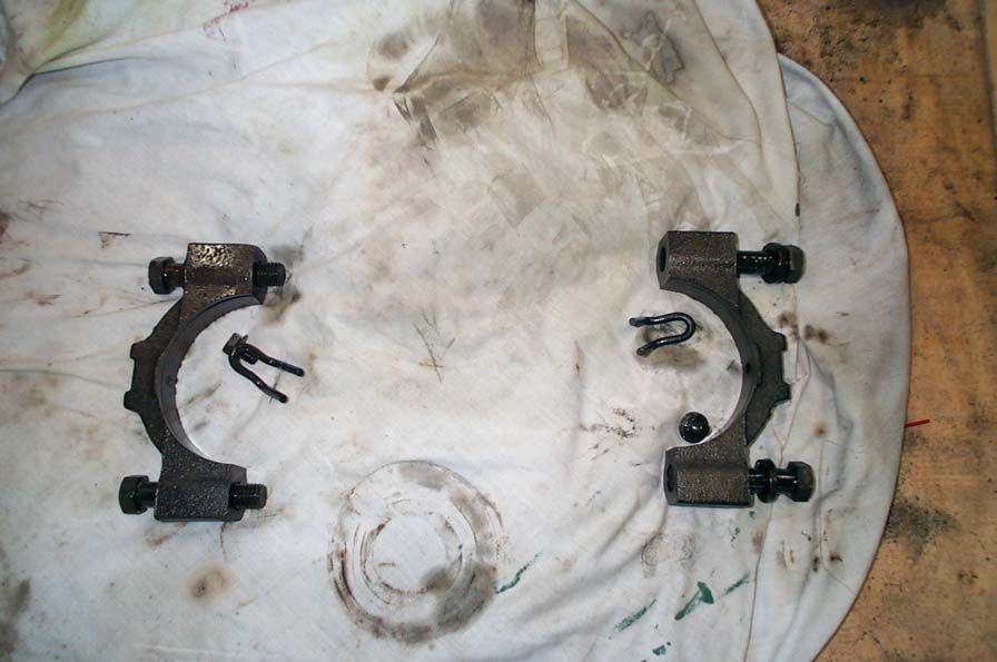 |
Bearing caps and adjuster locking bolts removed. | ||||||||||||||||||||||||||||||||||||||||||||||||||||||||||||||||||||||||||||||||||||||||||||||||||||||||||||||||||||||||||||||||||||||||||||||||||||||||||||||||||||||||||||||||||||||||||||||||||||||||||||||||||||||||||||||||||||||||||||||||||||||||||||||||||||||||||||||||||||||||||||||||||||||||||||||||||||||||||||||||||||||||||||||||||||||||||||||||||||||||||||||||||||||||||||||||||||||||||||||||||||||||||||||||||||||||||||||||||||||||||||||||||||
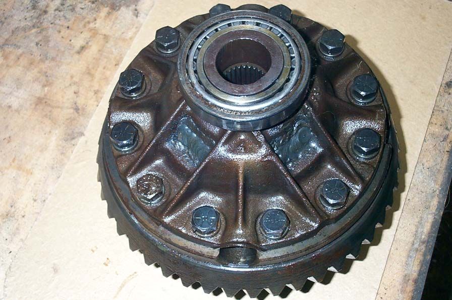
These pics are of the carrier removed. Mine is fully welded up making it a huge spool. I have read about some folks just welding the spider / side gears by filing in the valley's between the teeth and then reinstalling them. I personally have never understood this. It's not as if you need to save the carrier, since they are cheap and extremely plentiful. Also, I would think that in this manner, those welds would see quite a bit of shock loading. It's also a real bugger to reassemble the carrier and gears after you have just welded up the teeth and are trying to save the carrier.
|
|||||||||||||||||||||||||||||||||||||||||||||||||||||||||||||||||||||||||||||||||||||||||||||||||||||||||||||||||||||||||||||||||||||||||||||||||||||||||||||||||||||||||||||||||||||||||||||||||||||||||||||||||||||||||||||||||||||||||||||||||||||||||||||||||||||||||||||||||||||||||||||||||||||||||||||||||||||||||||||||||||||||||||||||||||||||||||||||||||||||||||||||||||||||||||||||||||||||||||||||||||||||||||||||||||||||||||||||||||||||||||||||||||||
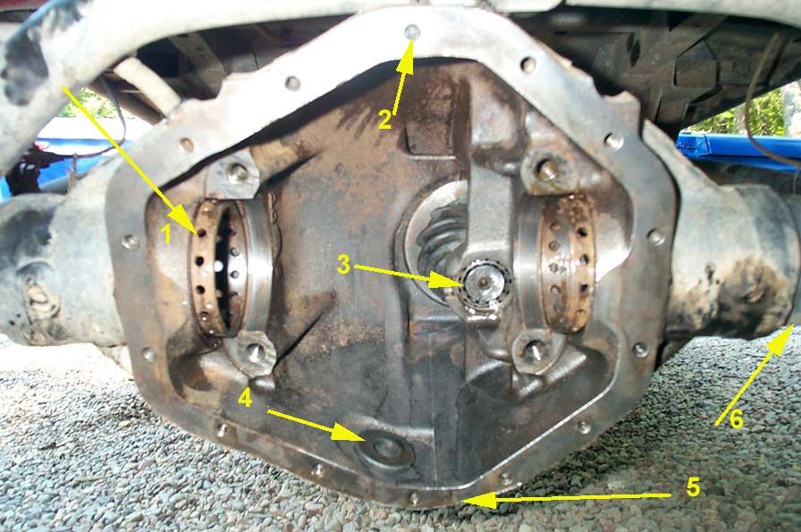 |
With the carrier removed, here's a look inside the diff:
|
||||||||||||||||||||||||||||||||||||||||||||||||||||||||||||||||||||||||||||||||||||||||||||||||||||||||||||||||||||||||||||||||||||||||||||||||||||||||||||||||||||||||||||||||||||||||||||||||||||||||||||||||||||||||||||||||||||||||||||||||||||||||||||||||||||||||||||||||||||||||||||||||||||||||||||||||||||||||||||||||||||||||||||||||||||||||||||||||||||||||||||||||||||||||||||||||||||||||||||||||||||||||||||||||||||||||||||||||||||||||||||||||||||
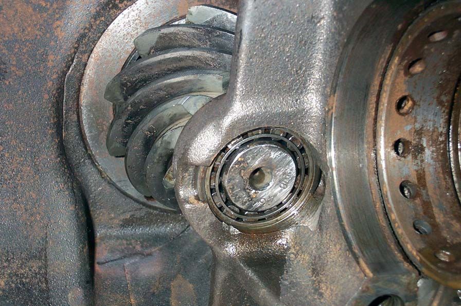 |
Close-up of pinion support bearing. The actual proper name for this is the "straddle bearing". | ||||||||||||||||||||||||||||||||||||||||||||||||||||||||||||||||||||||||||||||||||||||||||||||||||||||||||||||||||||||||||||||||||||||||||||||||||||||||||||||||||||||||||||||||||||||||||||||||||||||||||||||||||||||||||||||||||||||||||||||||||||||||||||||||||||||||||||||||||||||||||||||||||||||||||||||||||||||||||||||||||||||||||||||||||||||||||||||||||||||||||||||||||||||||||||||||||||||||||||||||||||||||||||||||||||||||||||||||||||||||||||||||||||
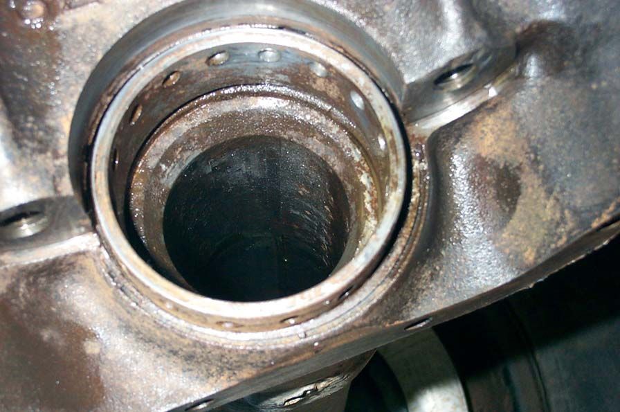 |
Threaded carrier preload adjuster and 1/2" thick axle tube. | ||||||||||||||||||||||||||||||||||||||||||||||||||||||||||||||||||||||||||||||||||||||||||||||||||||||||||||||||||||||||||||||||||||||||||||||||||||||||||||||||||||||||||||||||||||||||||||||||||||||||||||||||||||||||||||||||||||||||||||||||||||||||||||||||||||||||||||||||||||||||||||||||||||||||||||||||||||||||||||||||||||||||||||||||||||||||||||||||||||||||||||||||||||||||||||||||||||||||||||||||||||||||||||||||||||||||||||||||||||||||||||||||||||
 |
Housing. | ||||||||||||||||||||||||||||||||||||||||||||||||||||||||||||||||||||||||||||||||||||||||||||||||||||||||||||||||||||||||||||||||||||||||||||||||||||||||||||||||||||||||||||||||||||||||||||||||||||||||||||||||||||||||||||||||||||||||||||||||||||||||||||||||||||||||||||||||||||||||||||||||||||||||||||||||||||||||||||||||||||||||||||||||||||||||||||||||||||||||||||||||||||||||||||||||||||||||||||||||||||||||||||||||||||||||||||||||||||||||||||||||||||
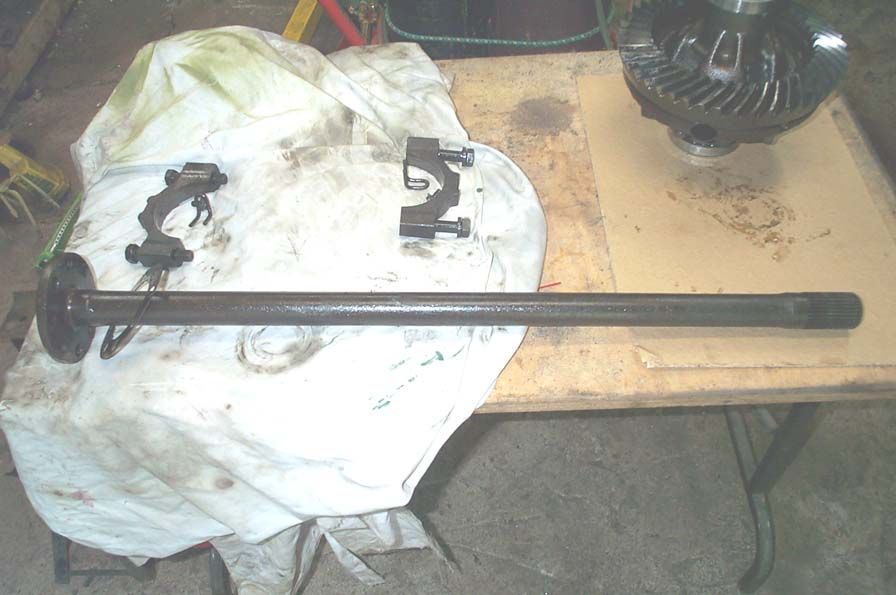 |
The left- and right-hand axle shafts are different lengths. The Left is the short side at 31-5/8". The Right is the long side at 37-5/8". |
||||||||||||||||||||||||||||||||||||||||||||||||||||||||||||||||||||||||||||||||||||||||||||||||||||||||||||||||||||||||||||||||||||||||||||||||||||||||||||||||||||||||||||||||||||||||||||||||||||||||||||||||||||||||||||||||||||||||||||||||||||||||||||||||||||||||||||||||||||||||||||||||||||||||||||||||||||||||||||||||||||||||||||||||||||||||||||||||||||||||||||||||||||||||||||||||||||||||||||||||||||||||||||||||||||||||||||||||||||||||||||||||||||
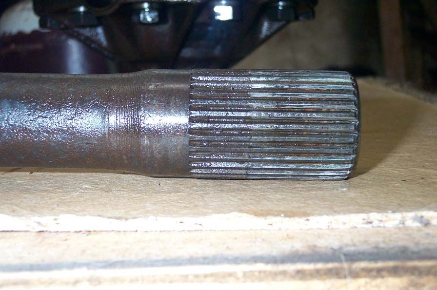 |
They are a large 30 spline axle. However, the pressure angle on the splines is not the same as other manufacturers (Dana, for example). | ||||||||||||||||||||||||||||||||||||||||||||||||||||||||||||||||||||||||||||||||||||||||||||||||||||||||||||||||||||||||||||||||||||||||||||||||||||||||||||||||||||||||||||||||||||||||||||||||||||||||||||||||||||||||||||||||||||||||||||||||||||||||||||||||||||||||||||||||||||||||||||||||||||||||||||||||||||||||||||||||||||||||||||||||||||||||||||||||||||||||||||||||||||||||||||||||||||||||||||||||||||||||||||||||||||||||||||||||||||||||||||||||||||
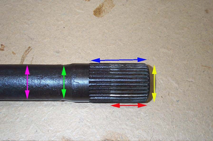 |
Dimensions on the shafts are:
|
||||||||||||||||||||||||||||||||||||||||||||||||||||||||||||||||||||||||||||||||||||||||||||||||||||||||||||||||||||||||||||||||||||||||||||||||||||||||||||||||||||||||||||||||||||||||||||||||||||||||||||||||||||||||||||||||||||||||||||||||||||||||||||||||||||||||||||||||||||||||||||||||||||||||||||||||||||||||||||||||||||||||||||||||||||||||||||||||||||||||||||||||||||||||||||||||||||||||||||||||||||||||||||||||||||||||||||||||||||||||||||||||||||
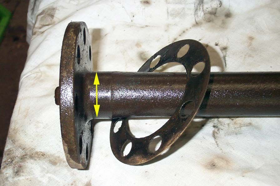 |
Axle diameter by the flange (yellow arrow): 1.458" | ||||||||||||||||||||||||||||||||||||||||||||||||||||||||||||||||||||||||||||||||||||||||||||||||||||||||||||||||||||||||||||||||||||||||||||||||||||||||||||||||||||||||||||||||||||||||||||||||||||||||||||||||||||||||||||||||||||||||||||||||||||||||||||||||||||||||||||||||||||||||||||||||||||||||||||||||||||||||||||||||||||||||||||||||||||||||||||||||||||||||||||||||||||||||||||||||||||||||||||||||||||||||||||||||||||||||||||||||||||||||||||||||||||
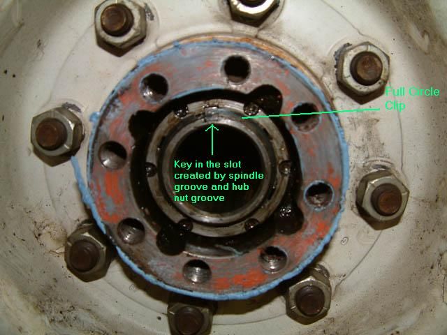
| The following pics, courtesy of Benny "Bigger Valves" Langford and Clay "yotacowboy" Moulton, illustrate an alternate method of retaining the wheel bearings in the 14-Bolt. For the record, the axle shown here is from an '87 1 ton Chevy V30 (crewcab, 4x4, 350 tbi engine). | |||||||||||||||||||||||||||||||||||||||||||||||||||||||||||||||||||||||||||||||||||||||||||||||||||||||||||||||||||||||||||||||||||||||||||||||||||||||||||||||||||||||||||||||||||||||||||||||||||||||||||||||||||||||||||||||||||||||||||||||||||||||||||||||||||||||||||||||||||||||||||||||||||||||||||||||||||||||||||||||||||||||||||||||||||||||||||||||||||||||||||||||||||||||||||||||||||||||||||||||||||||||||||||||||||||||||||||||||||||||||||||||||||||
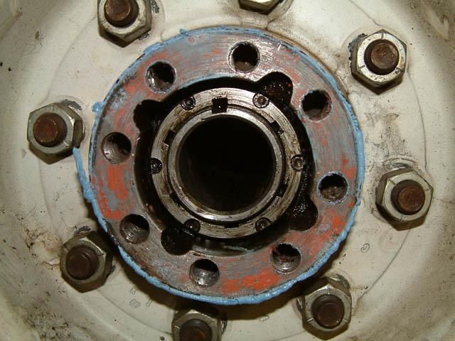 |
It's a very simple setup that consists of one hub nut, one key, and one clip-ring. The nut accepts the regular 6-prong 14-Bolt socket and has 6 square grooves around its inner diameter. These grooves are what you line up with the spindle groove to make the key way, as shown here. To adjust the bearings, tighten the hub nut down until the the correct preload is achieved (see the .pdf manual at the start of this article if you are not sure how to do this), and then tighten the nut further until the next groove in the nut lines up with the spindle groove. |
||||||||||||||||||||||||||||||||||||||||||||||||||||||||||||||||||||||||||||||||||||||||||||||||||||||||||||||||||||||||||||||||||||||||||||||||||||||||||||||||||||||||||||||||||||||||||||||||||||||||||||||||||||||||||||||||||||||||||||||||||||||||||||||||||||||||||||||||||||||||||||||||||||||||||||||||||||||||||||||||||||||||||||||||||||||||||||||||||||||||||||||||||||||||||||||||||||||||||||||||||||||||||||||||||||||||||||||||||||||||||||||||||||
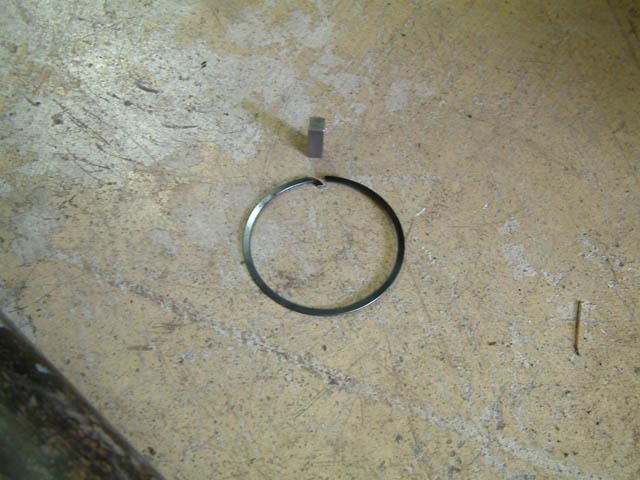 |
This pic shows the clip-ring and the small rectangular key. | ||||||||||||||||||||||||||||||||||||||||||||||||||||||||||||||||||||||||||||||||||||||||||||||||||||||||||||||||||||||||||||||||||||||||||||||||||||||||||||||||||||||||||||||||||||||||||||||||||||||||||||||||||||||||||||||||||||||||||||||||||||||||||||||||||||||||||||||||||||||||||||||||||||||||||||||||||||||||||||||||||||||||||||||||||||||||||||||||||||||||||||||||||||||||||||||||||||||||||||||||||||||||||||||||||||||||||||||||||||||||||||||||||||
 |
Once the preload is adjusted and the grooves in the nut and spindle are lines up, simply slide the key in the key way and put on the clip ring. The clip-ring has a curved end that fits in the spindle groove to securely block the key from backing out. The clip is very thin and flimsy which makes it easy to remove with just a screwdriver and allows it to fit snugly around the spindle in the threads. Part numbers for this style spindle hardware are:
|
||||||||||||||||||||||||||||||||||||||||||||||||||||||||||||||||||||||||||||||||||||||||||||||||||||||||||||||||||||||||||||||||||||||||||||||||||||||||||||||||||||||||||||||||||||||||||||||||||||||||||||||||||||||||||||||||||||||||||||||||||||||||||||||||||||||||||||||||||||||||||||||||||||||||||||||||||||||||||||||||||||||||||||||||||||||||||||||||||||||||||||||||||||||||||||||||||||||||||||||||||||||||||||||||||||||||||||||||||||||||||||||||||||
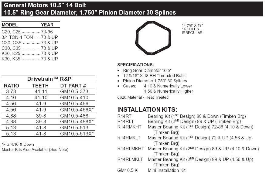
Dana Catalogue Page on GM 14-Bolt (10.5")
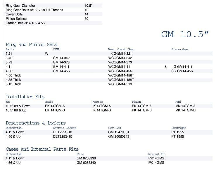
West Coast Differentials Catalogue Page on the GM 14bolt (10.5")
GM 14-Bolt Specs(all data for single-rear-wheel (SRW) truck 14-Bolt axle - others may vary).
The Different Types of 14-BoltBefore we get into the different types of 14-Bolt axle, a quick review of some truck terminology that will keep popping up is in order. Truck LingoWhen talking about truck, especially with respect t rear axles, we often use the terms SRW, DRW, C&C, and WMS. Here's what they mean: |
|||||||||||||||||||||||||||||||||||||||||||||||||||||||||||||||||||||||||||||||||||||||||||||||||||||||||||||||||||||||||||||||||||||||||||||||||||||||||||||||||||||||||||||||||||||||||||||||||||||||||||||||||||||||||||||||||||||||||||||||||||||||||||||||||||||||||||||||||||||||||||||||||||||||||||||||||||||||||||||||||||||||||||||||||||||||||||||||||||||||||||||||||||||||||||||||||||||||||||||||||||||||||||||||||||||||||||||||||||||||||||||||||||||
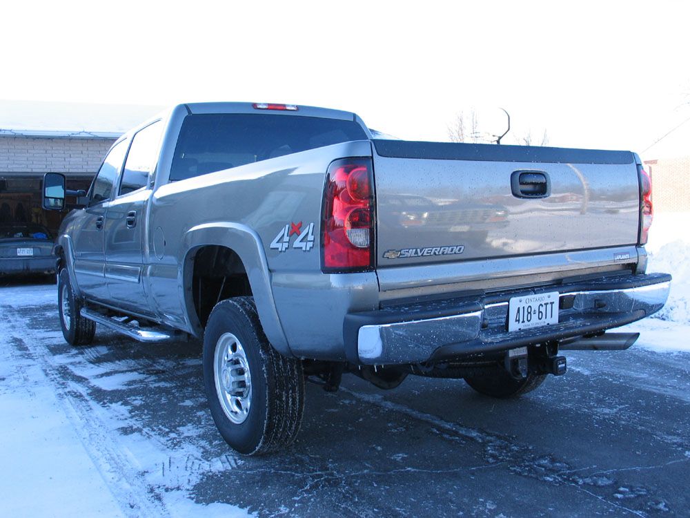 |
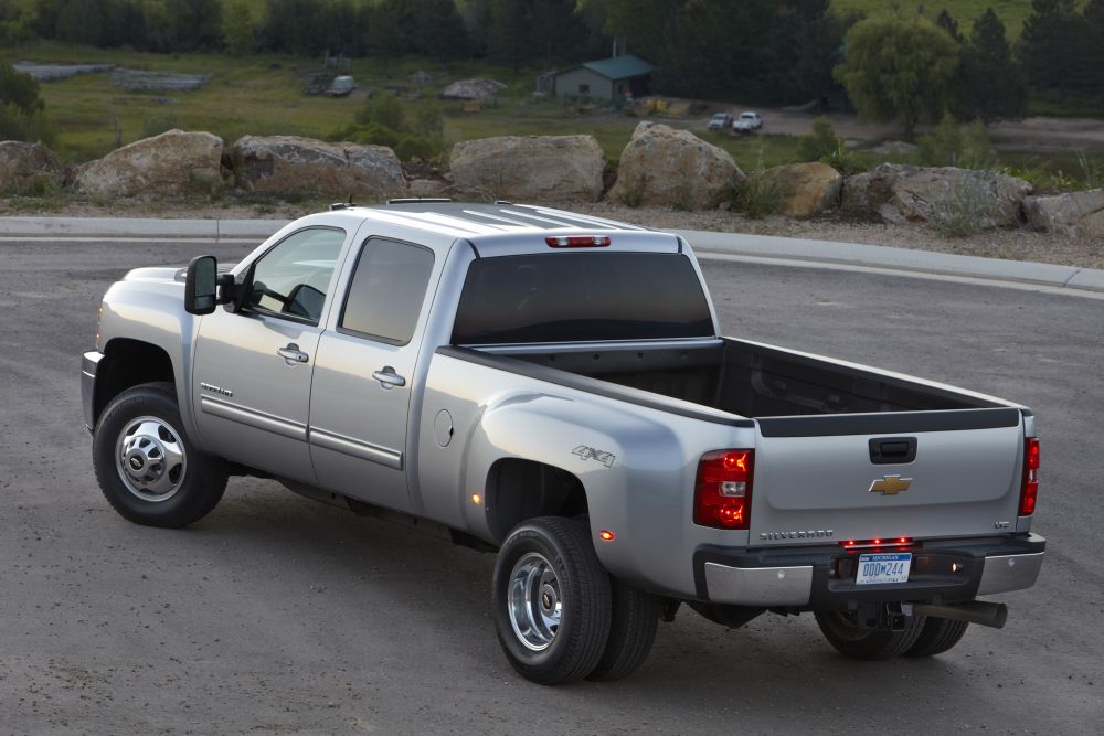
SRW stands for "Single Rear Wheel" and refers to a truck that has a single wheel on each end of its rear axle. Your average pickup truck is a SRW truck with a SRW axle. This is my 2007 Chevy Silverado HD2500 "SRW" truck. |
||||||||||||||||||||||||||||||||||||||||||||||||||||||||||||||||||||||||||||||||||||||||||||||||||||||||||||||||||||||||||||||||||||||||||||||||||||||||||||||||||||||||||||||||||||||||||||||||||||||||||||||||||||||||||||||||||||||||||||||||||||||||||||||||||||||||||||||||||||||||||||||||||||||||||||||||||||||||||||||||||||||||||||||||||||||||||||||||||||||||||||||||||||||||||||||||||||||||||||||||||||||||||||||||||||||||||||||||||||||||||||||||||||
|
DRW stands for "Dual Rear Wheel" and refers to a truck that has two wheels on each end of its rear axle. One-ton, heavy-duty pickup trucks are sometimes DRW and are often referred to as "Dually's". This is a 2012 Chevy Silverado HD "DRW" truck. Picture courtesy of and copyright GM Company. |
||||||||||||||||||||||||||||||||||||||||||||||||||||||||||||||||||||||||||||||||||||||||||||||||||||||||||||||||||||||||||||||||||||||||||||||||||||||||||||||||||||||||||||||||||||||||||||||||||||||||||||||||||||||||||||||||||||||||||||||||||||||||||||||||||||||||||||||||||||||||||||||||||||||||||||||||||||||||||||||||||||||||||||||||||||||||||||||||||||||||||||||||||||||||||||||||||||||||||||||||||||||||||||||||||||||||||||||||||||||||||||||||||||
|
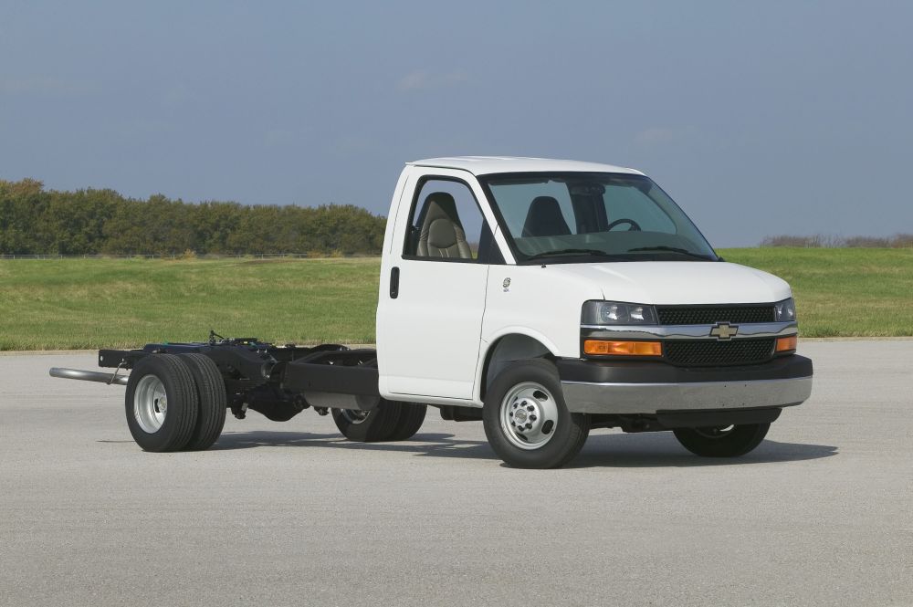
C&C stands for "Cab and Chassis" which refers to a truck configuration that is sold without a "box" on the back. It is, literally, just a cab and a chassis (frame), like the one shown here. This is a Chevy C-class C&C truck (so bigger than a one-ton pickup, and it wouldn;t have a 14-Bolt rear axle but the pic clearly illustrates the "C&C" concept. C&C trucks are sold commercially for use as work trucks to customers who need to fit their own specialized bodies such as service trucks, welding trucks, wreckers, and small dump trucks. Picture courtesy of and copyright GM Company. |
||||||||||||||||||||||||||||||||||||||||||||||||||||||||||||||||||||||||||||||||||||||||||||||||||||||||||||||||||||||||||||||||||||||||||||||||||||||||||||||||||||||||||||||||||||||||||||||||||||||||||||||||||||||||||||||||||||||||||||||||||||||||||||||||||||||||||||||||||||||||||||||||||||||||||||||||||||||||||||||||||||||||||||||||||||||||||||||||||||||||||||||||||||||||||||||||||||||||||||||||||||||||||||||||||||||||||||||||||||||||||||||||||||
|
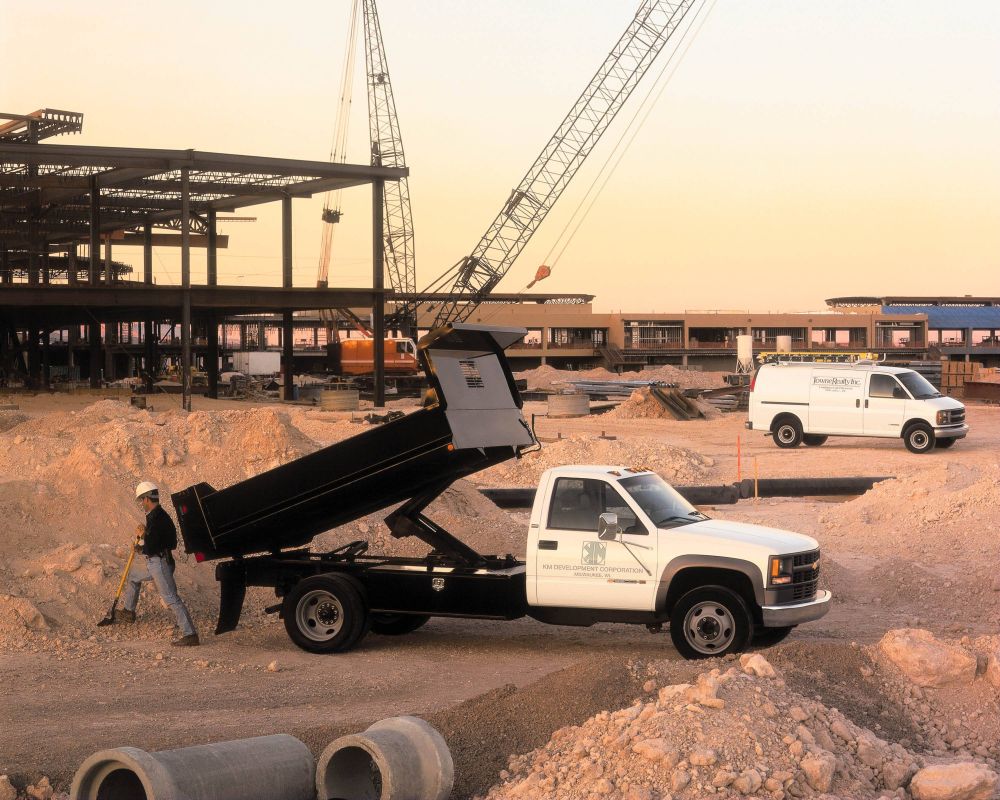
As they are intended for heavy-duty work trucks, C&C trucks almost always also have dual rear wheels. This is Chevy C3500 HD one-ton C&C truck fitted with a small dump box. Picture courtesy of and copyright GM Company. |
||||||||||||||||||||||||||||||||||||||||||||||||||||||||||||||||||||||||||||||||||||||||||||||||||||||||||||||||||||||||||||||||||||||||||||||||||||||||||||||||||||||||||||||||||||||||||||||||||||||||||||||||||||||||||||||||||||||||||||||||||||||||||||||||||||||||||||||||||||||||||||||||||||||||||||||||||||||||||||||||||||||||||||||||||||||||||||||||||||||||||||||||||||||||||||||||||||||||||||||||||||||||||||||||||||||||||||||||||||||||||||||||||||
WMS stands for "Wheel Mounting Surface". So when we refer to the width of an axle in terms of WMS-WMS we mean the distance between the wheel mounting surfaces (on the hubs). We do this to eliminate the variables of wheel width, wheel offset, and tire width which, if not eliminated, would make for an almost infinite number of possible widths.
Back to the 14-BoltThere are many different 14-Bolt axles available, with an almost dizzying array of possible widths, tube OD's, hub types, brakes etc. Fortunately, all are pretty similar, a huge number of parts interchange. *CAUTION* - With this axle, as indeed with all things "axle" - there are no hard and fast laws - for every "fact" I shall present, I know there's at least one person out there, possibly many, who claim they own or know of exceptions. This is very likely true, and is due to the way in which OEM vehicle construction occurs. This variability and ambiguity is just a fact of life and unfortunately cannot be avoided or completely resolved. What follows is what I believe to be true, or the most correct, information based on the research I have done and the letters I have received from what I judge to be the most reputable sources. Use the data with caution - "your mileage may vary" as they saying goes. 14-Bolts can be broken down into 4 broad groups. There is also at least one year break that brings minor changes, but this is in fact far less significant than the "type" of 14-Bolt axle in question. Once again - this article is concerned only with GM 14-Bolt full-float rear drive axles. With that said, the following table attempts to capture the data.
* Note that these names (or designations) are of my own invention. They are not the official designations used by the manufacturer. Unfortunately, I do not know what the official designations are, or I wold have used them. So, don't call up your local junkyard and ask if they have a 14-Bolt with "Type B" hubs and "Type 1" shafts - they will look at you funny (yes, even over the phone!) I have simply invented and used these terms to help illustrate the differences and similarities between the different axle types that are out there. Notes:
Type A and Type B HubsThe following pics, courtesy of Brawler, illustrate the differences between the Type A and Type B hubs. |
|||||||||||||||||||||||||||||||||||||||||||||||||||||||||||||||||||||||||||||||||||||||||||||||||||||||||||||||||||||||||||||||||||||||||||||||||||||||||||||||||||||||||||||||||||||||||||||||||||||||||||||||||||||||||||||||||||||||||||||||||||||||||||||||||||||||||||||||||||||||||||||||||||||||||||||||||||||||||||||||||||||||||||||||||||||||||||||||||||||||||||||||||||||||||||||||||||||||||||||||||||||||||||||||||||||||||||||||||||||||||||||||||||||
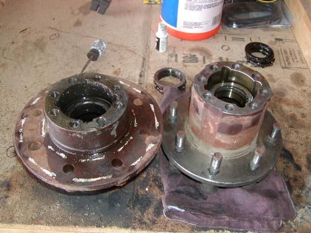 |
Type A hub on left. Type B hub on right. |
||||||||||||||||||||||||||||||||||||||||||||||||||||||||||||||||||||||||||||||||||||||||||||||||||||||||||||||||||||||||||||||||||||||||||||||||||||||||||||||||||||||||||||||||||||||||||||||||||||||||||||||||||||||||||||||||||||||||||||||||||||||||||||||||||||||||||||||||||||||||||||||||||||||||||||||||||||||||||||||||||||||||||||||||||||||||||||||||||||||||||||||||||||||||||||||||||||||||||||||||||||||||||||||||||||||||||||||||||||||||||||||||||||
 |
Type A (SRW / Van) 14-Bolt hub. The flat, machined flange you see here (through which the wheel studs are poking) is the wheel mounting surface or WMS we keep referring too. Notice how short the central part of the hub that sticks out past the WMS is. |
||||||||||||||||||||||||||||||||||||||||||||||||||||||||||||||||||||||||||||||||||||||||||||||||||||||||||||||||||||||||||||||||||||||||||||||||||||||||||||||||||||||||||||||||||||||||||||||||||||||||||||||||||||||||||||||||||||||||||||||||||||||||||||||||||||||||||||||||||||||||||||||||||||||||||||||||||||||||||||||||||||||||||||||||||||||||||||||||||||||||||||||||||||||||||||||||||||||||||||||||||||||||||||||||||||||||||||||||||||||||||||||||||||
 |
Type B (C&C / DRW) 14-Bolt hub. Notice how much longer the central part of the hub that sticks out past the WMS is, compared to the Type A hub, above. |
||||||||||||||||||||||||||||||||||||||||||||||||||||||||||||||||||||||||||||||||||||||||||||||||||||||||||||||||||||||||||||||||||||||||||||||||||||||||||||||||||||||||||||||||||||||||||||||||||||||||||||||||||||||||||||||||||||||||||||||||||||||||||||||||||||||||||||||||||||||||||||||||||||||||||||||||||||||||||||||||||||||||||||||||||||||||||||||||||||||||||||||||||||||||||||||||||||||||||||||||||||||||||||||||||||||||||||||||||||||||||||||||||||
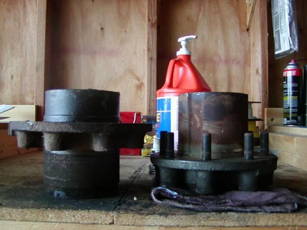 |
Type A hub on left. Type B hub on right. This picture is taken with the two hubs sitting on the bench simulating the position they would each be in when mounted on the spindle. You can clearly see the higher height of the WMS of the Type A hub on the left that translates into the wider WMS-WMS width of an axle fitted with Type A hubs compared to one fitted with Type B hubs. |
||||||||||||||||||||||||||||||||||||||||||||||||||||||||||||||||||||||||||||||||||||||||||||||||||||||||||||||||||||||||||||||||||||||||||||||||||||||||||||||||||||||||||||||||||||||||||||||||||||||||||||||||||||||||||||||||||||||||||||||||||||||||||||||||||||||||||||||||||||||||||||||||||||||||||||||||||||||||||||||||||||||||||||||||||||||||||||||||||||||||||||||||||||||||||||||||||||||||||||||||||||||||||||||||||||||||||||||||||||||||||||||||||||
Different YearsThe year split is '72-88 (so-called "first design") and 89+ (so-called "second-design). Of course, there may be variations. Differences between these years are noted below. Where the difference is known only to apply to certain "types", I shall indicate this.
When working on a 14-Bolt axle, the biggest difference between the first and second design to be aware of is the different bearings used in the diff. The wheel bearings, pinion seal, and front pinion bearing are common to both first- and second-design axles. The first-design axle uses a different rear pinion bearing than the second-design axle. And the really confusing part is that the first-design and second-design axles use the same pinion straddle bearing EXCEPT for the 1984-1985 first-design axles which use a different straddle bearing from all the rest. Perhaps the best way to explain this is to simply list the part numbers. The seal & bearing numbers are*:
* Cone = the roller or bearing, Cup = the race. |
|||||||||||||||||||||||||||||||||||||||||||||||||||||||||||||||||||||||||||||||||||||||||||||||||||||||||||||||||||||||||||||||||||||||||||||||||||||||||||||||||||||||||||||||||||||||||||||||||||||||||||||||||||||||||||||||||||||||||||||||||||||||||||||||||||||||||||||||||||||||||||||||||||||||||||||||||||||||||||||||||||||||||||||||||||||||||||||||||||||||||||||||||||||||||||||||||||||||||||||||||||||||||||||||||||||||||||||||||||||||||||||||||||||
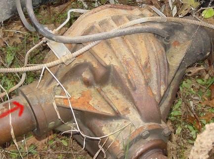 |
This picture illustrates the heavily ribbed centre section of the second design 14-Bolt housing (ignore the red arrow). | ||||||||||||||||||||||||||||||||||||||||||||||||||||||||||||||||||||||||||||||||||||||||||||||||||||||||||||||||||||||||||||||||||||||||||||||||||||||||||||||||||||||||||||||||||||||||||||||||||||||||||||||||||||||||||||||||||||||||||||||||||||||||||||||||||||||||||||||||||||||||||||||||||||||||||||||||||||||||||||||||||||||||||||||||||||||||||||||||||||||||||||||||||||||||||||||||||||||||||||||||||||||||||||||||||||||||||||||||||||||||||||||||||||
14-Bolt Wheel StudsOne of the most popular modifications to any 14-Bolt axle used in an offroad truck is to remove the huge, heavy drum brakes and swap to disc brakes. I wrote a compete article on this process which you can read for detailed info. One thing though, is that when you swap from drums to discs, the wheel studs are usually no longer long enough because they have to pass through the disc and the hub (that's how the disc is held to the hub). Over the years there has been much discussion and experimentation with using different wheel studs, with different folks reporting different levels of satisfaction with different options. As far as I know there has never been a universally accepted one perfect solution, but the following data I consider quite reliable and should at least allow you to narrow down some choices with which to experiment to achieve a level of satisfaction you are comfortable with. How to Cure the 14-Bolt of it's Achilles Heel weak link!The mighty 14-Bolt does have 1 terrible weak link - an Achilles Heel. It's the crappy, lousy design, weak, expensive and hard to find straps for holding the U-joint in the pinion yoke. |
|||||||||||||||||||||||||||||||||||||||||||||||||||||||||||||||||||||||||||||||||||||||||||||||||||||||||||||||||||||||||||||||||||||||||||||||||||||||||||||||||||||||||||||||||||||||||||||||||||||||||||||||||||||||||||||||||||||||||||||||||||||||||||||||||||||||||||||||||||||||||||||||||||||||||||||||||||||||||||||||||||||||||||||||||||||||||||||||||||||||||||||||||||||||||||||||||||||||||||||||||||||||||||||||||||||||||||||||||||||||||||||||||||||
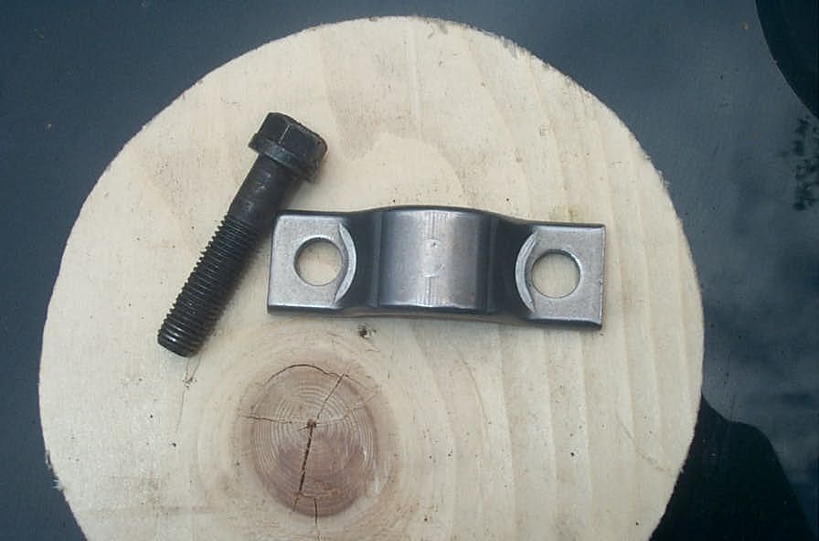 |
The proper straps are a pain to find.
No parts store I have ever tried, from NAPA to Car Quest ever has them. That leaves only the GM dealership, where the strap (GM p/n: 3920486) will set you back $3 EACH! and the bolts (GM p/n: 458300 or 14018700) another $2 EACH. |
||||||||||||||||||||||||||||||||||||||||||||||||||||||||||||||||||||||||||||||||||||||||||||||||||||||||||||||||||||||||||||||||||||||||||||||||||||||||||||||||||||||||||||||||||||||||||||||||||||||||||||||||||||||||||||||||||||||||||||||||||||||||||||||||||||||||||||||||||||||||||||||||||||||||||||||||||||||||||||||||||||||||||||||||||||||||||||||||||||||||||||||||||||||||||||||||||||||||||||||||||||||||||||||||||||||||||||||||||||||||||||||||||||
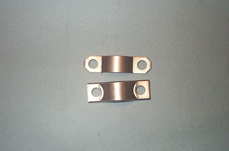 |
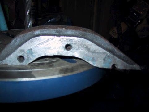
As for all the local and big chain parts stores - they will all gladly sell you a "strap kit" for a "1-ton GM rear axle" or "GM 10.5" rear end" or a "14-Bolt full floater" or a "1980 Chevy K30 1 ton 4x4 " or whatever else you have to say to them to get one - but, in my experience (NAPA, Car Quest, Canadian Tire, and a couple of local independents) they are all WRONG, and it won't fit at all. The top strap is the one the parts stores will sell you, the bottom the GM part. |
||||||||||||||||||||||||||||||||||||||||||||||||||||||||||||||||||||||||||||||||||||||||||||||||||||||||||||||||||||||||||||||||||||||||||||||||||||||||||||||||||||||||||||||||||||||||||||||||||||||||||||||||||||||||||||||||||||||||||||||||||||||||||||||||||||||||||||||||||||||||||||||||||||||||||||||||||||||||||||||||||||||||||||||||||||||||||||||||||||||||||||||||||||||||||||||||||||||||||||||||||||||||||||||||||||||||||||||||||||||||||||||||||||
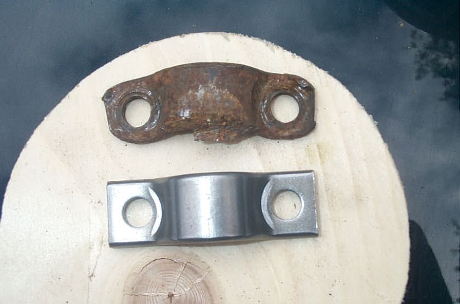 |
In any case - the stock straps are weak and badly designed - very soon they end up looking like this. | ||||||||||||||||||||||||||||||||||||||||||||||||||||||||||||||||||||||||||||||||||||||||||||||||||||||||||||||||||||||||||||||||||||||||||||||||||||||||||||||||||||||||||||||||||||||||||||||||||||||||||||||||||||||||||||||||||||||||||||||||||||||||||||||||||||||||||||||||||||||||||||||||||||||||||||||||||||||||||||||||||||||||||||||||||||||||||||||||||||||||||||||||||||||||||||||||||||||||||||||||||||||||||||||||||||||||||||||||||||||||||||||||||||
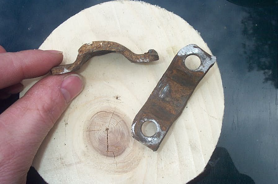 |
Complete junk!! | ||||||||||||||||||||||||||||||||||||||||||||||||||||||||||||||||||||||||||||||||||||||||||||||||||||||||||||||||||||||||||||||||||||||||||||||||||||||||||||||||||||||||||||||||||||||||||||||||||||||||||||||||||||||||||||||||||||||||||||||||||||||||||||||||||||||||||||||||||||||||||||||||||||||||||||||||||||||||||||||||||||||||||||||||||||||||||||||||||||||||||||||||||||||||||||||||||||||||||||||||||||||||||||||||||||||||||||||||||||||||||||||||||||
Fortunately - there is a solution - and a very cool one at that - read all about it - the High Angle Driveline 1410 Pinion Yoke kit Shaving the 14-BoltThe only real disadvantage to the 14b is the huge size of the differential, and subsequent scarcity of ground clearance. I must admit, in stock form, they do tend to hang a little low and get hung up on stuff. Most users will "shave" them. This can range from simply smoothing out the bottom with a hand grinder, to cutting a big chunk out of the bottom of the diff housing and machining down the diameter of the ring gear. The following pics illustrate the nicest case of the later, more extreme, shaving job that I have come across. It is the work of Phil Jensen, from Ottawa, Canada. |
|||||||||||||||||||||||||||||||||||||||||||||||||||||||||||||||||||||||||||||||||||||||||||||||||||||||||||||||||||||||||||||||||||||||||||||||||||||||||||||||||||||||||||||||||||||||||||||||||||||||||||||||||||||||||||||||||||||||||||||||||||||||||||||||||||||||||||||||||||||||||||||||||||||||||||||||||||||||||||||||||||||||||||||||||||||||||||||||||||||||||||||||||||||||||||||||||||||||||||||||||||||||||||||||||||||||||||||||||||||||||||||||||||||
 |
The diff before the shave. | ||||||||||||||||||||||||||||||||||||||||||||||||||||||||||||||||||||||||||||||||||||||||||||||||||||||||||||||||||||||||||||||||||||||||||||||||||||||||||||||||||||||||||||||||||||||||||||||||||||||||||||||||||||||||||||||||||||||||||||||||||||||||||||||||||||||||||||||||||||||||||||||||||||||||||||||||||||||||||||||||||||||||||||||||||||||||||||||||||||||||||||||||||||||||||||||||||||||||||||||||||||||||||||||||||||||||||||||||||||||||||||||||||||
 |
The piece cut from the diff housing. Phil used an abrasive wheel/blade in a circular saw to start, and finished with a reciprocating saw. Starett blades are reportedly good for this. | ||||||||||||||||||||||||||||||||||||||||||||||||||||||||||||||||||||||||||||||||||||||||||||||||||||||||||||||||||||||||||||||||||||||||||||||||||||||||||||||||||||||||||||||||||||||||||||||||||||||||||||||||||||||||||||||||||||||||||||||||||||||||||||||||||||||||||||||||||||||||||||||||||||||||||||||||||||||||||||||||||||||||||||||||||||||||||||||||||||||||||||||||||||||||||||||||||||||||||||||||||||||||||||||||||||||||||||||||||||||||||||||||||||
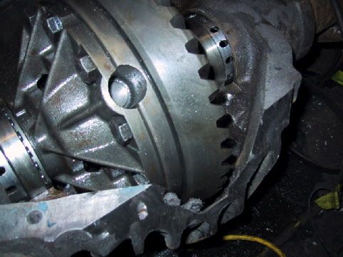 |
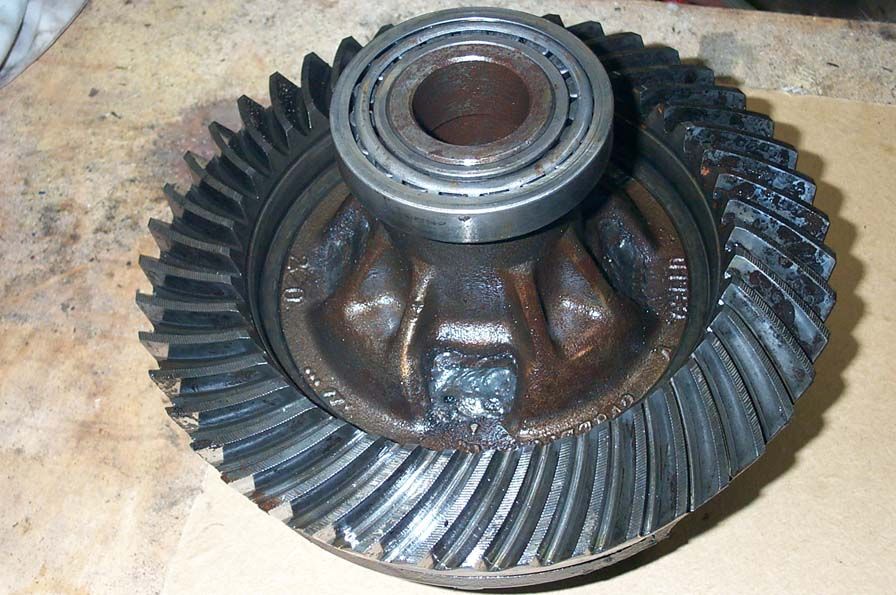
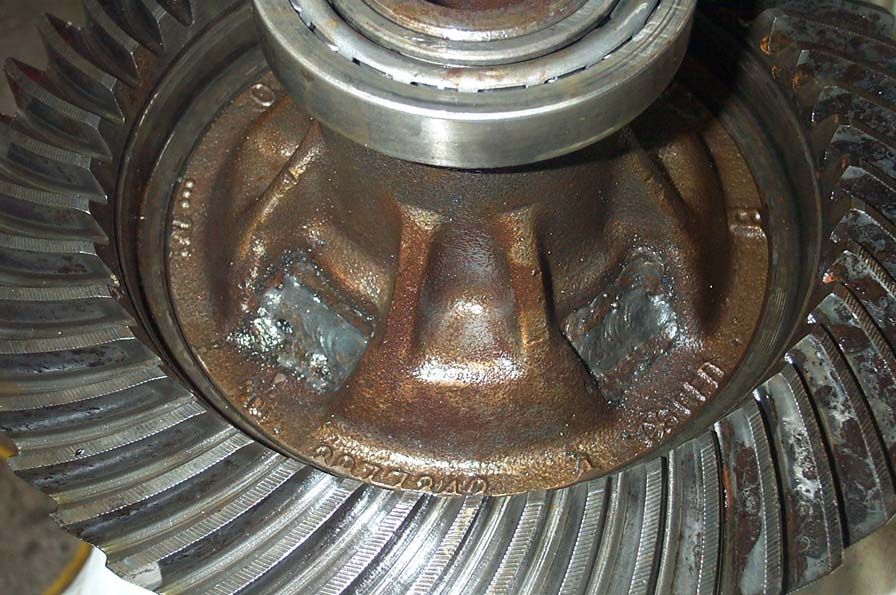
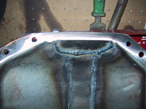
After the cut of the housing, this is the carrier back in place, before it was machined down. It was then removed and approx. 1/4" machined from the OD of the ring gear. This did not effect the performance or durability of the gear set at all. | ||||||||||||||||||||||||||||||||||||||||||||||||||||||||||||||||||||||||||||||||||||||||||||||||||||||||||||||||||||||||||||||||||||||||||||||||||||||||||||||||||||||||||||||||||||||||||||||||||||||||||||||||||||||||||||||||||||||||||||||||||||||||||||||||||||||||||||||||||||||||||||||||||||||||||||||||||||||||||||||||||||||||||||||||||||||||||||||||||||||||||||||||||||||||||||||||||||||||||||||||||||||||||||||||||||||||||||||||||||||||||||||||||||
 |
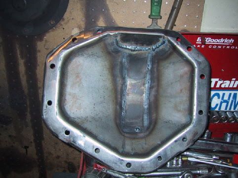
The 1/2" thick mild steel plate that was TIG welded to the housing. | ||||||||||||||||||||||||||||||||||||||||||||||||||||||||||||||||||||||||||||||||||||||||||||||||||||||||||||||||||||||||||||||||||||||||||||||||||||||||||||||||||||||||||||||||||||||||||||||||||||||||||||||||||||||||||||||||||||||||||||||||||||||||||||||||||||||||||||||||||||||||||||||||||||||||||||||||||||||||||||||||||||||||||||||||||||||||||||||||||||||||||||||||||||||||||||||||||||||||||||||||||||||||||||||||||||||||||||||||||||||||||||||||||||
 |
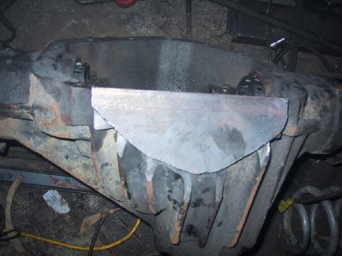
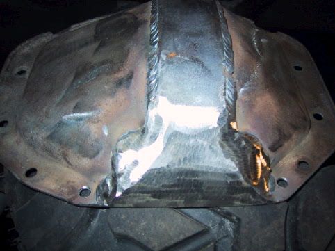
The plate welded in place | ||||||||||||||||||||||||||||||||||||||||||||||||||||||||||||||||||||||||||||||||||||||||||||||||||||||||||||||||||||||||||||||||||||||||||||||||||||||||||||||||||||||||||||||||||||||||||||||||||||||||||||||||||||||||||||||||||||||||||||||||||||||||||||||||||||||||||||||||||||||||||||||||||||||||||||||||||||||||||||||||||||||||||||||||||||||||||||||||||||||||||||||||||||||||||||||||||||||||||||||||||||||||||||||||||||||||||||||||||||||||||||||||||||
 |
The gears machined and re-installed Just over 2" of clearance was gained. That's the same (at the diff) as going from 35" to 39" tires!! |
||||||||||||||||||||||||||||||||||||||||||||||||||||||||||||||||||||||||||||||||||||||||||||||||||||||||||||||||||||||||||||||||||||||||||||||||||||||||||||||||||||||||||||||||||||||||||||||||||||||||||||||||||||||||||||||||||||||||||||||||||||||||||||||||||||||||||||||||||||||||||||||||||||||||||||||||||||||||||||||||||||||||||||||||||||||||||||||||||||||||||||||||||||||||||||||||||||||||||||||||||||||||||||||||||||||||||||||||||||||||||||||||||||
Originally, Phil made a quick cover by altering a stock cover. It didn't last well enough for his liking, so in the end he constructed a complete custom cover from 3/8" plate steel, which has reportedly held up very well. Unfortunately, I have no pictures of the later cover, but here are some of the original.
From the research I have done (I have no personal practical experience) the methods that have been used successfully for trimming the OD of a ring gear for a radical shave job are:
I believe the preferred method is the wire EDM. Here's what engineersedge.com has to say about EDM.
14-Bolt Part Numbers from the On-line Listing at DTS
14-Bolt Wheel bearings and Seals
|
|||||||||||||||||||||||||||||||||||||||||||||||||||||||||||||||||||||||||||||||||||||||||||||||||||||||||||||||||||||||||||||||||||||||||||||||||||||||||||||||||||||||||||||||||||||||||||||||||||||||||||||||||||||||||||||||||||||||||||||||||||||||||||||||||||||||||||||||||||||||||||||||||||||||||||||||||||||||||||||||||||||||||||||||||||||||||||||||||||||||||||||||||||||||||||||||||||||||||||||||||||||||||||||||||||||||||||||||||||||||||||||||||||||
|