 |
Dana 60 High Clearance Steering Arms By Bill "BillaVista" Ansell |
IntroductionI have serious issues with my steering. I always have. I don't know if I'm a terrible driver, or it's just par for the course - but virtually every run I do I come back with my tie-rod and/or drag link looking like a long bow or a pretzel. It really came to a head a few weeks ago, when during a run, I bent the tie rod back pretty badly. Nothing unusual there, but this time, I did it so badly that when the front axle subsequently articulated from left-wheel-down to left-wheel-up while simultaneously being steered right, the drag link/tie rod bracket contacted my track bar bracket and ripped it in two. This left me with a very softly-sprung coil rig with no track bar, virtually no steering whatsoever, and a front axle dancing laterally back and forth as much as 2 feet. Worse - I had to limp it out of a tough trail, and then get it on the trailer in that shape! |
 |
ENOUGH!!!! I needed high clearance steering arms to move the steering linkage up out of harm's way (because let's face it - it's not likely my driving will improve :-). Also, I want (actually, desperately need) full hydrostatic (hydraulic) steering one day, so I decided that eventually I would design that system around these same high clearance steering arms. So, off I went, web-shopping for ultimate Dana 60 High Clearance Steering Arms. I wanted them to be strong, of course, but also professionally machined. You see, I can flame cut some from a piece of 1" mild steel myself - but this time, I knew eventually they would have to stand up to full hydraulic steering - so I needed something a little better than I could turn out. It didn't take me long to find them. At a unique and highly specialized shop, right here in Canada (for once!). Over The Top (OTT) Industries are a small, highly specialized shop in Vancouver, BC that, as their web site proclaims, specialize in "steering and gearing". I talked to Ben Olsen at OTT - what an enormously nice guy to talk to. He has to be the nicest, most pleasant, most well-spoken guy I've ever talked to at a 4x4 shop. Great - that's nice...so you can take him to tea with the Queen....but are his steering arms any good??? Read on.... Part 1 - The Why? |
|
 |
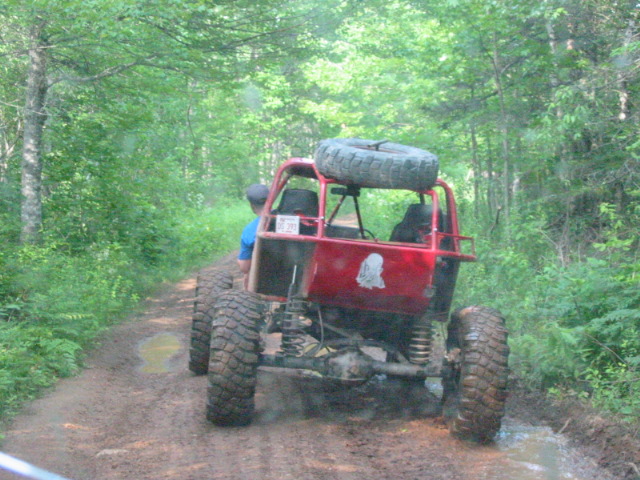
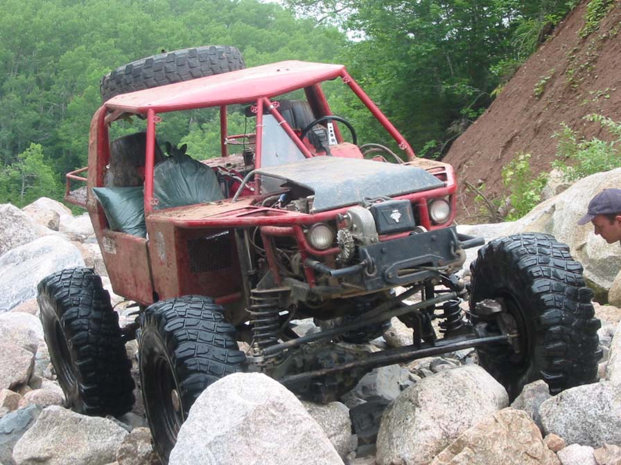
From way back, when I first got the Wolf, I have enjoyed driving it by brail! | ||||
 |
And you can see here, a year later, I've learned nothing, still gleefully smashing the steering into rocks, grinning like an idiot :-) | ||||
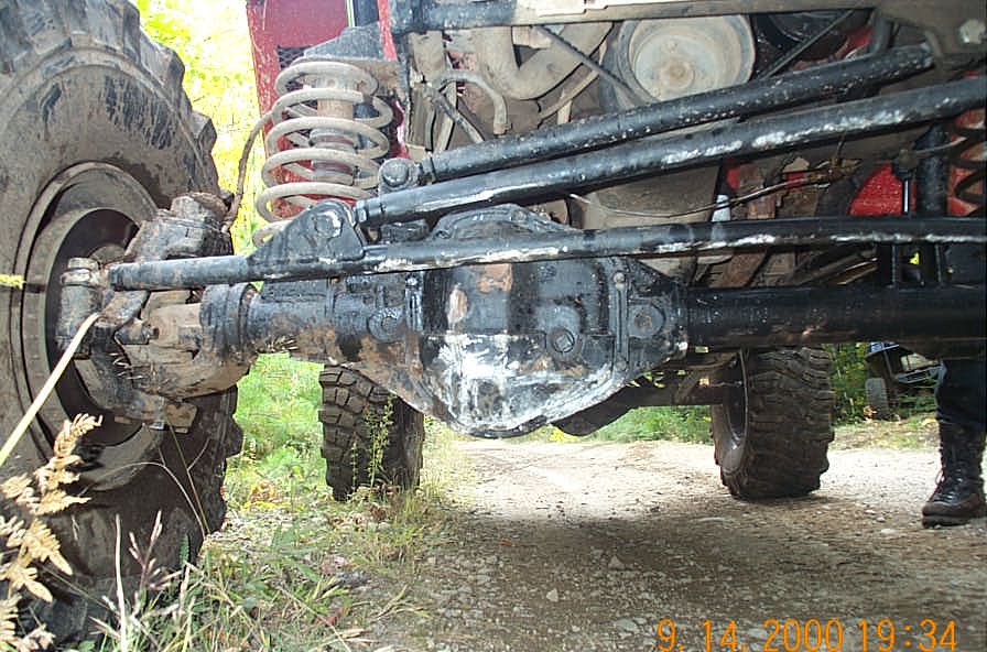 |
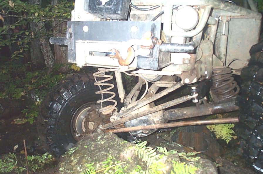
So the steering invariably ends up looking like this after a weekend... | ||||
 |
...or worse...like this. Tie rod bent back so far that drag link/tie rod bracket contacted track bar bracket and ripped it off. | ||||
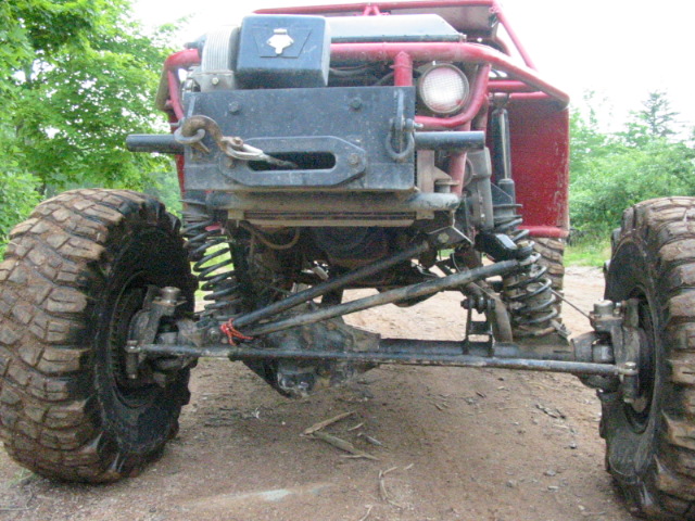 |
Leaving me with virtually no steering, and an axle all over the place. | ||||
 |
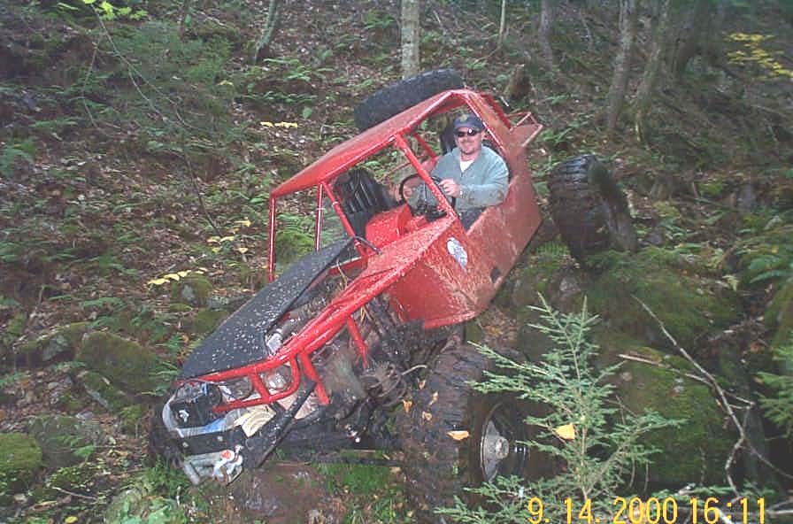
Which was a little more challenging than I'd really like to limp back to the trailer. Without the track bar, turning the steering wheel just shoved the body off the axle, side to side. Sometimes it was all the way left... |
||||
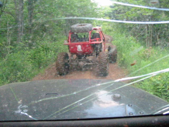 |
...sometimes it was all the way right! Something HAD to be done - this was starting to be uncool! |
||||
Part 2 - The ArmsSo I did some surfing, did some reading, did some calling around, and ended up talking to Ben Olson at OTT Industries in Vancouver, BC, Canada. The Dana 60 High Clearance Steering Arms OTT produce stand alone at the top of the pile in my opinion, and that's why I decided to order them. What makes them the best choice - that's what I'll explain in this section |
|||||
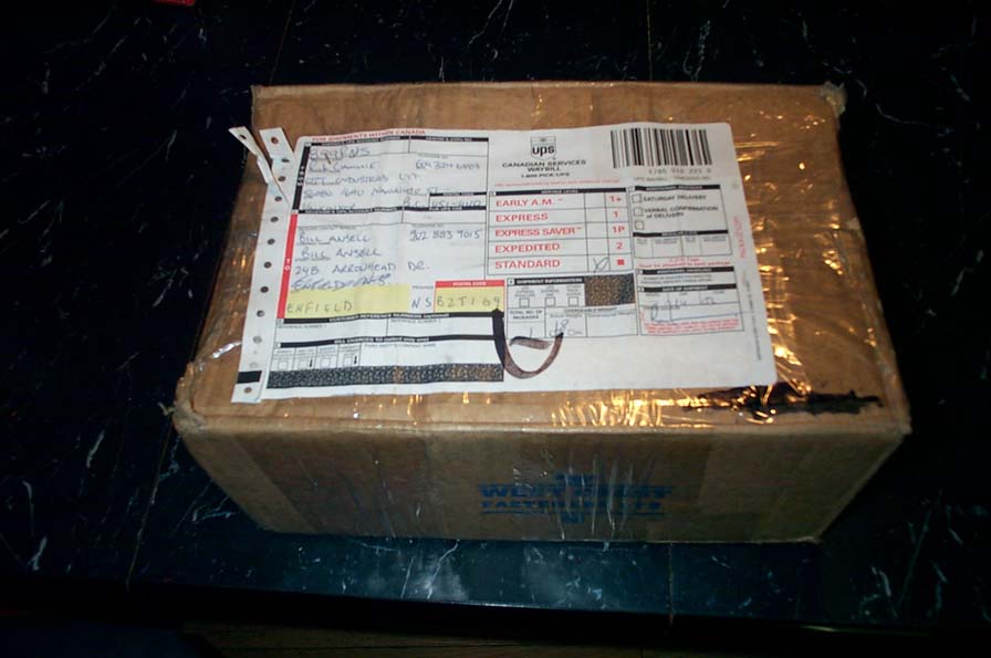 |
First off, Ben was super to talk to on the phone. We discussed various technical factors relating to my arms - from wheel backspace concerns to choice of steering components (rod end / Heim joint or tapered tie rod end). After I explained exactly what I wanted and how I planned to run it, the boys at OTT got to work, and a few days later the package arrived at my doorstop on the other side of the country. I knew there were goodies inside, because it weighed a TON, even though it was not very big. |
||||
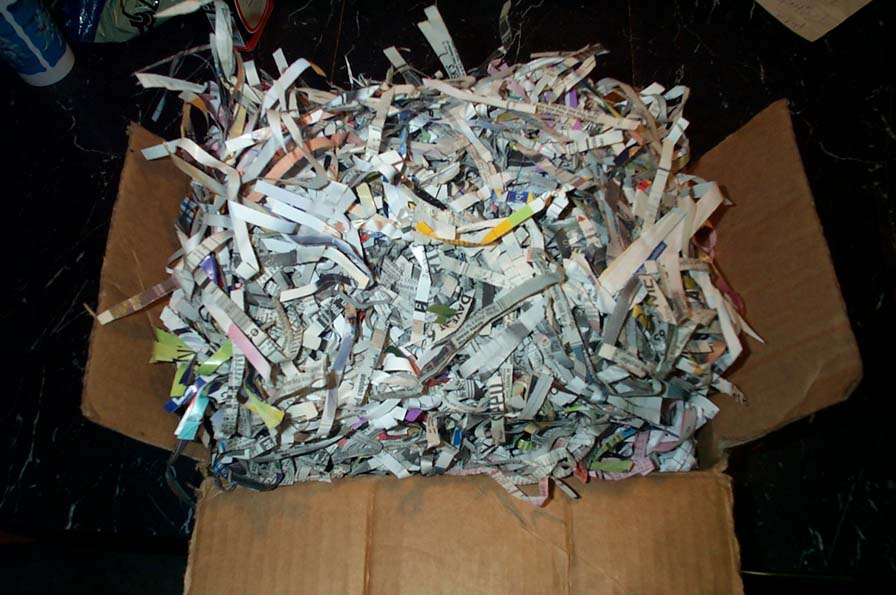 |
So I greedily ripped it open, and found, much to my chagrin, that OTT had shipped me an extremely heavy rat's nest! Just kidding - the arms were well packaged inside and protected by a bunch of shredded paper. |
||||
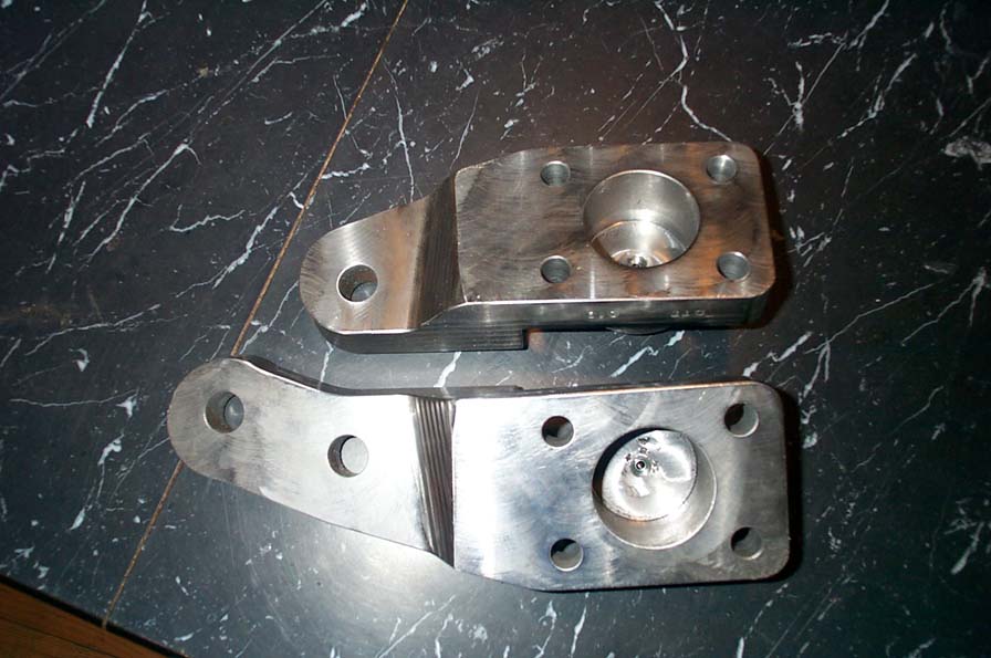 |
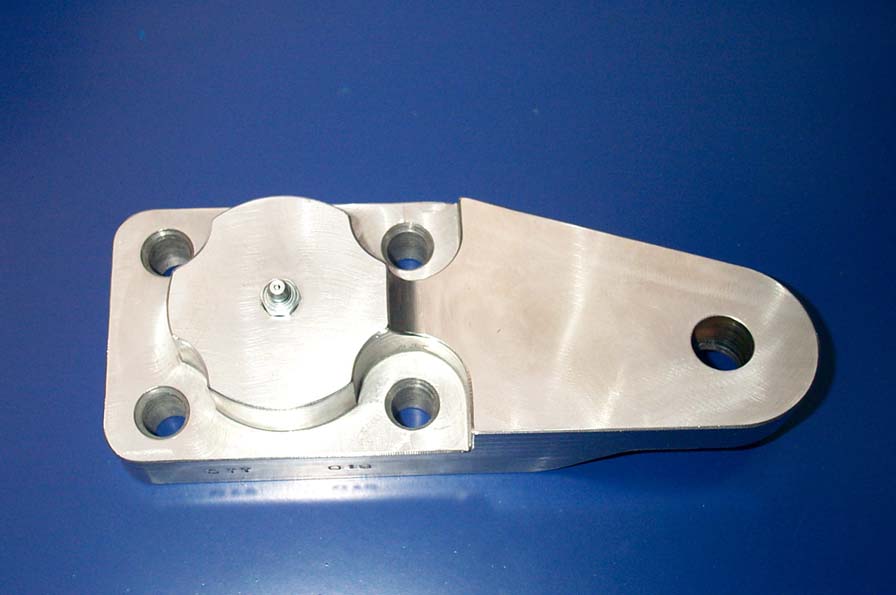
Aah - there're the little beauties now! | ||||
Features of the OTT arms include:
The following pics illustrate the arms and their features: |
|||||
|
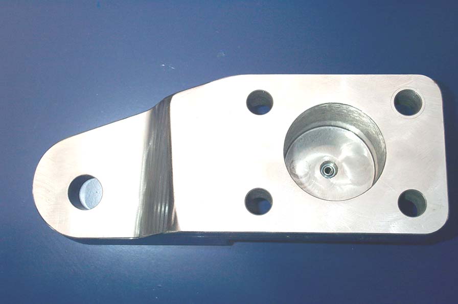
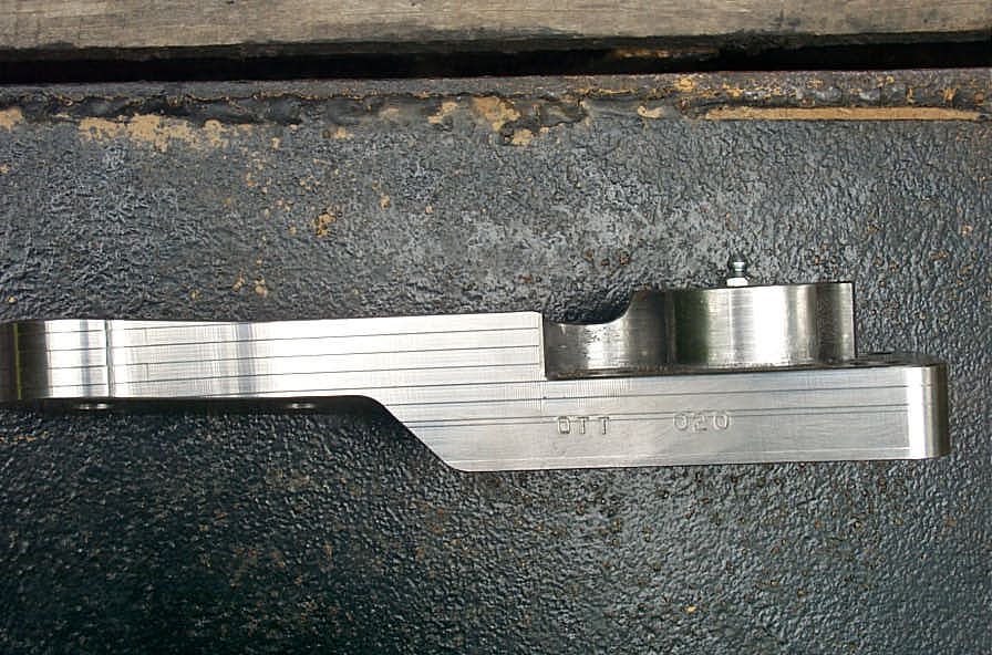
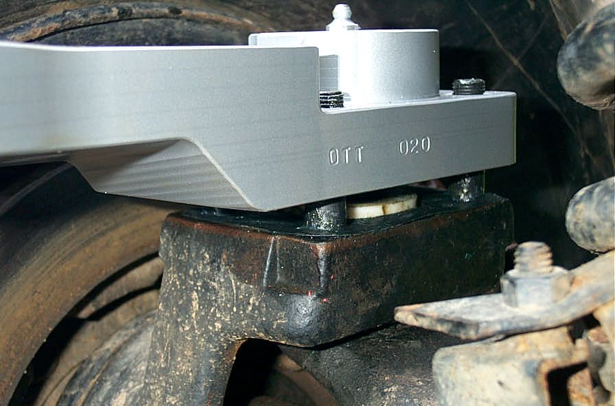
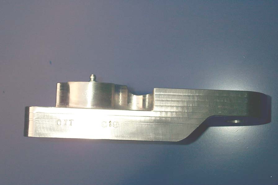
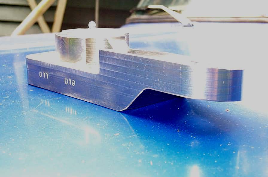
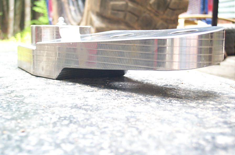
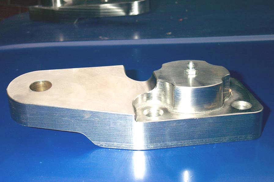
They're CNC machined from a single piece of mild carbon steel on an OKK Vertical Machining Center. Ben, the crafty bugger, wouldn't give up the exact SAE or ASTM spec of the steel - no matter how I weaseled or how many angles I tried. Can't say I blame him - a man's gotta have some trade secrets. He did give up that it was in the 60-70 000 psi tensile strength range. This is the driver's side arm. Despite the 1 piece design, there is ample room to get a socket on each of the mounting nuts, due to the machined reliefs. |
||||
|
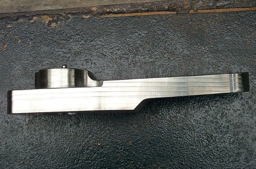
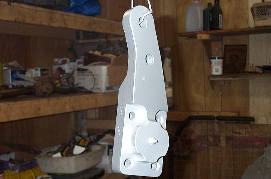
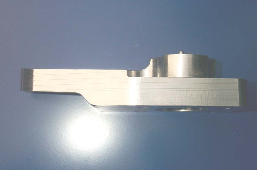
These 2 pics are side views of the driver's side arm, and clearly show the integrated kingpin cap. I personally really enjoy this feature. Anything that means less parts to fool with, and more 1 piece simple, brute-strength is good with me! | ||||
 |
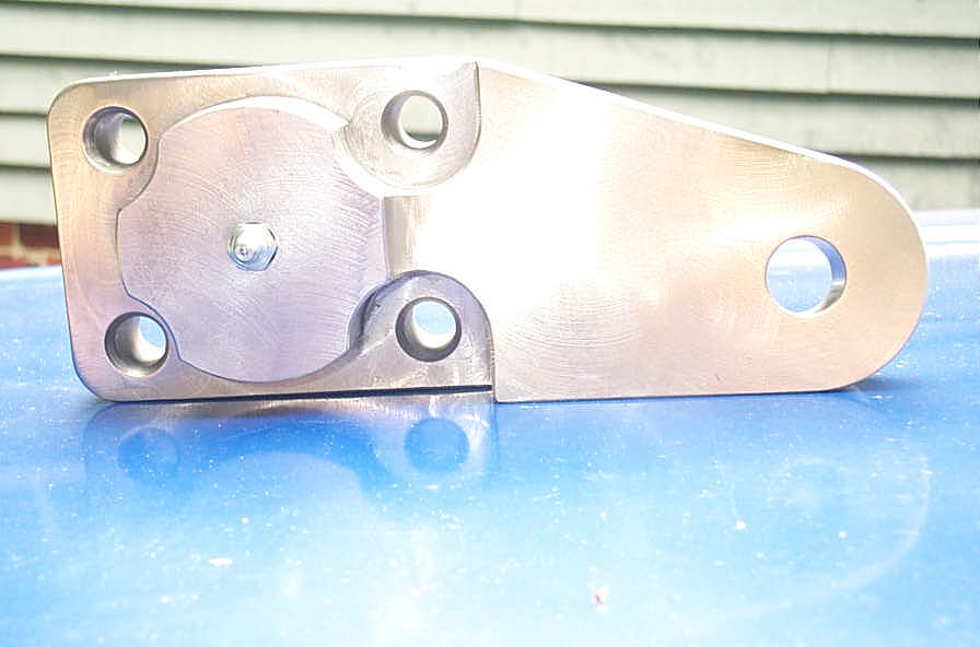
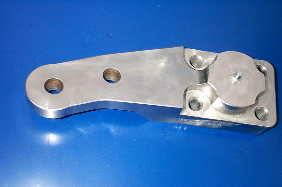
Underside shot of the driver's side arm. You can see that I chose to have the steering linkage holes in my arms machined for a straight 3/4" SAE bolt, as that is what I use in my current steering linkage, and I plan to do so with my new (eventual) hydraulic system also. The arms can be machined to accept standard automotive tie rod ends also if you prefer. |
||||
 |
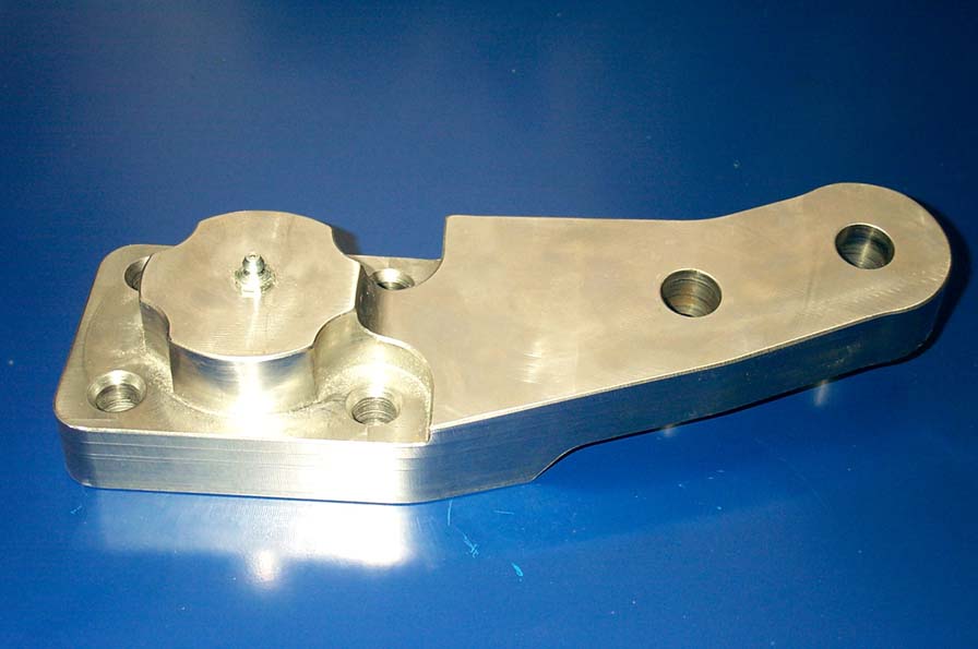
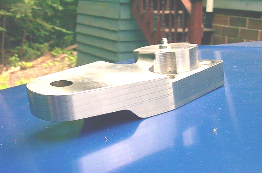
Another "plane" view of the driver's side arm. The tie rod linkage mounting hole is approximately 5.25" from the centre of the kingpin. | ||||
|
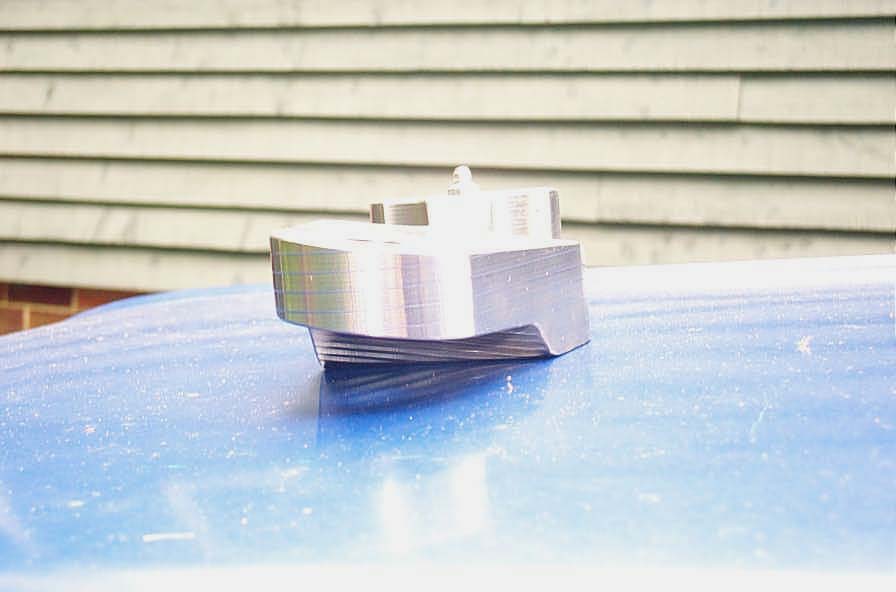
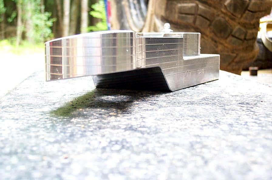
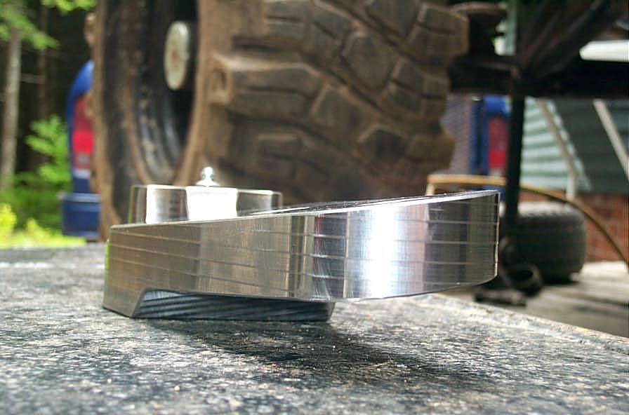
These pics show the real beauty of the OTT arms. They are cleverly designed and machined so that they compensate for the Dana 60 kingpin inclination (camber) and present a horizontal mounting plane for the steering linkage ends. This means that, whether you use TRE's or Heim joints, at static rest with the OTT arms your steering linkage ends have a flat, horizontal mounting surface, so that none of their precious misalignment angle is eaten up by the stock Dana 60 kingpin inclination. That in turn translates into the maximum possible linkage misalignment during axle articulation, and therefore the greatest possible wheel travel unencumbered by steering linkage binding. The clever design also incorporates a slight rise in the steering arm over the plane of the top of the knuckle, to accommodate leaf springs in the spring-over-axle configuration, while still retaining use of stock length mounting studs (for VERY good reasons, explained later), AND providing the proper mounting depth for those using tapered stud tie rod ends. All this, at the same time as angling in sufficiently to accommodate even 44" tires on stock hummer rims without interference!! In other words.....TRICK AS HELL !! |
||||
 |
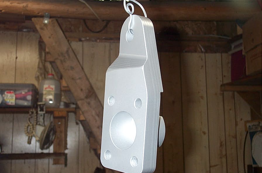
This is the passenger's side arm, machined to accept the tie rod and drag link. | ||||
|
The passenger's side arm of course has all the same features as the driver's side arm, as described above. | ||||
 |
Right side view of the passenger's side arm. | ||||
 |
Left side view of the passenger's side arm. | ||||
 |
Close-up showing the 60° taper seat for the tapered nuts that secure the arm to the studs installed in the steering knuckle. | ||||
 |
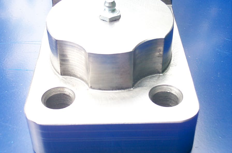
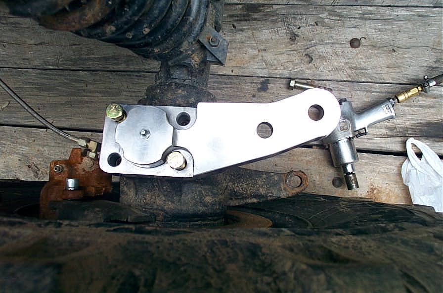
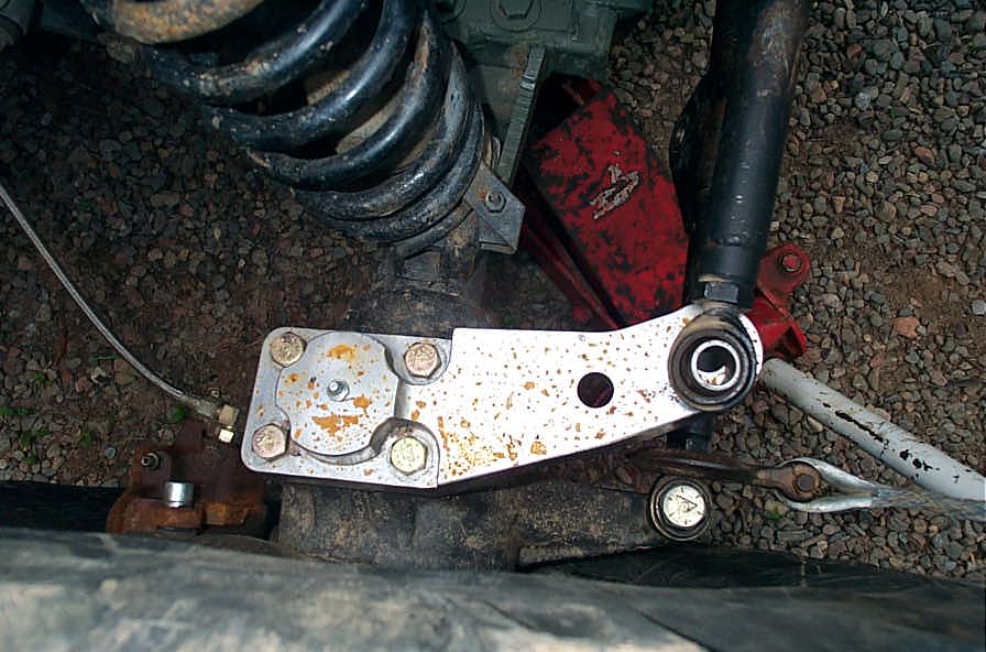
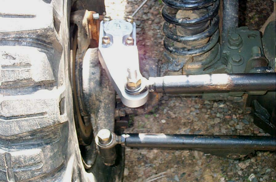
Test fit installation of driver's side arm shows how tie rod hole is slightly aft and inside of stock location. | ||||
 |
This accommodates virtually any size tire combined with any size rim with any backspacing. This pic shows a 325/85/R16 Michelin XML Military Radial (approx 38x14.50) mounted on a 16" x 9.5" steel rim with 4.5" backspace. The OTT arms have been used with stock Hummer rims running 42x15.00 TSLs. | ||||
 |
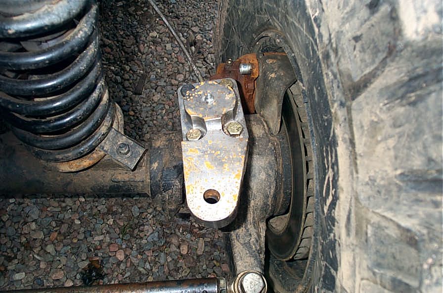
Test fit of the passenger side arm. | ||||
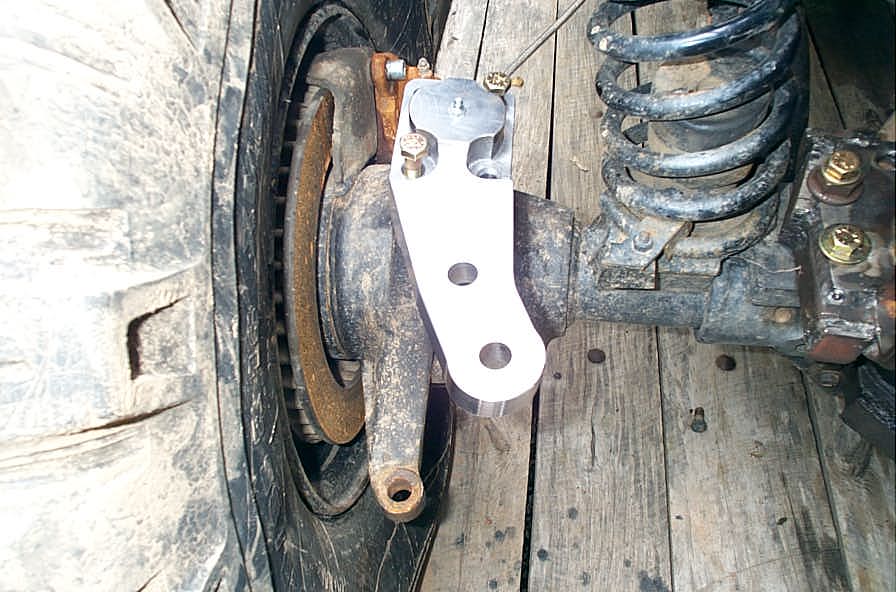 |
The front hole is the drag link hole. | ||||
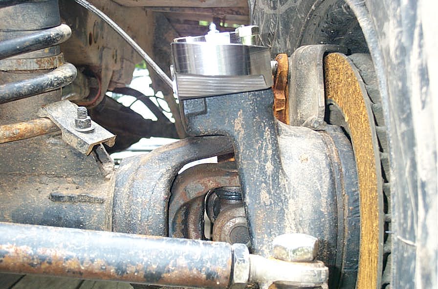 |
Test shot illustrating how the angle of the OTT arms cancel out the stock Dana 60 kingpin inclination to provide a level mounting plane for your steering linkage ends. | ||||
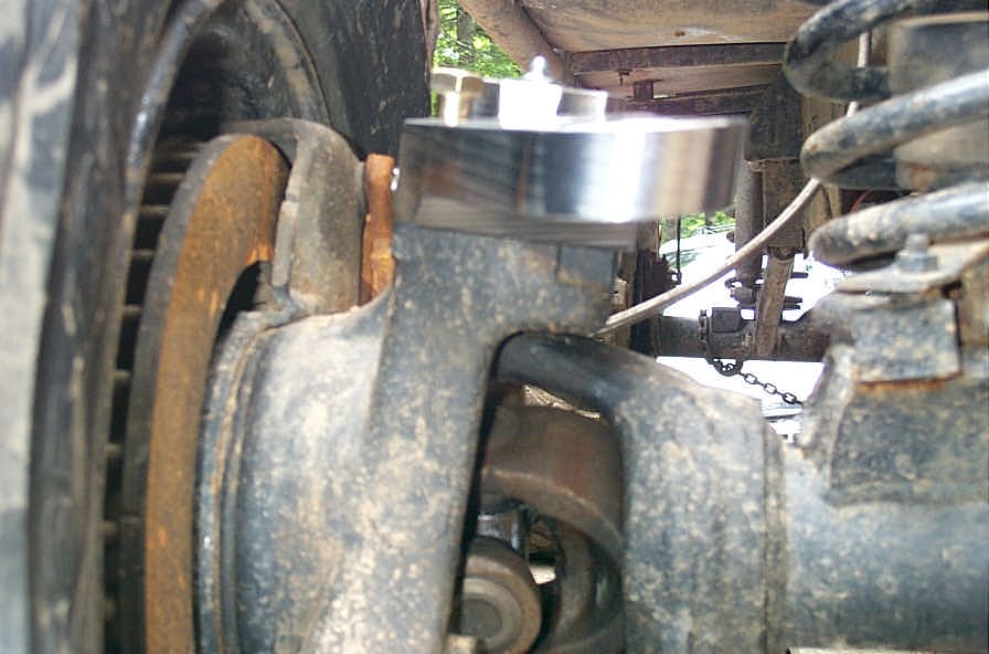 |
Test shot illustrating how the angle of the OTT arms cancel out the stock Dana 60 kingpin inclination to provide a level mounting plane for your steering linkage ends. | ||||
Part 3 - Installation and TestingBefore I detail the installation, I should mention my one "beef' with the OTT arms. My beef is this: there are absolutely no instructions of any kind included. I know, you're thinking: "big deal, they're just bolt-on steering arms". And for those of you smarter than a box of hammers, that may well be true. But I have a gift - if there's any possible way to screw something up - I WILL find it. And sure enough, there were several "gotchas" I fell into during my installation. In retrospect, I don't believe any of the issues that I stumbled onto are issues with the product - but merely screw ups that all could have easily been avoided with an instruction sheet. Whether they are product issues, my unbelievable ineptitude that could only happen to me and are therefore of no concern, or just things that you're glad I messed up and warned you about - you will have to decide for yourself! |
|||||
 |
The first "gotcha" greeted me the morning after I initially installed the arms. I had to order the required GM mounting studs, as my local dealer had none in stock. As I waited for the studs to come in so I could properly mount the arms as they were intended, I installed the arms as kingpin caps only, using regular SAE Grade 8 1/2-20NF bolts. I did this mostly so I could play around with measuring / test fitting steering linkages, but also secretly 'coz I knew one of my wheeling buddies was coming over and I really wanted to show them off :-) From this I learned 2 important things. First, the arms, despite their beautiful, shiny, machined appearance out of the box are shipped raw, untreated steel. That means, if they sit outside, and it rains, like of course it did for me, they will begin to surface rust immediately! Doh! |
||||
 |
The second is: DO NOT use regular bolts or use an impact wrench to install the arms - even temporarily. The steel from which they are machined is actually fairly soft - and using a regular hex head bolt where a stud and tapered nut are specified, ESPECIALLY if you tighten said improper bolts with an impact wrench (even just to initial tightness and not final torque) you WILL gall the arms, and chew up the steel around the tapered seats. Doh! The solution to the second "gotcha" is easy - use the correct hardware for installation (just like the guy who made the arms told you to, silly) and do not use an impact gun. I simply dressed the area around the holes lightly with a fine file and I was ok. |
||||
 |
The solution to the first part is easy too. Paint, powder coat or otherwise treat the arms before installation. No big deal, just wish I had known. I simply removed the light surface rust with steel wool (where do steel sheep come from - I've never seen one?) and then painted them with some Bowman Industries industrial anti-rust coating (I think that's paint to you and me). I used "Detroit Diesel Silver" | ||||
 |
Me being the Mr Bean of the workshop, this, of course, uncovered another "gotcha". The mounting holes for the four 1/2" knuckle studs are very precisely machined for an exact fit. This is an EXCELLENT thing, that I'll get into more in a moment. However, it does mean that if you slap on 3 or 4 coats of spray paint without covering the holes, you will gum up the holes and screw up the exact tolerances, which of course you will only realize later when you are trying to install them. So, when you paint, mask the four 1/2" mounting holes. And here I thought I was being clever by masking the tip of the grease fitting with a dab of grease! | ||||
Alright - I've made several references to mounting style / hardware, and it's importance, so let's get into it. First, let me convince you of why this is such an important consideration. To begin with, this is one of, if not THE, most important bolted joint assembly on you rig. Why? Two reasons, really. One, because obviously the entire steering system, and therefore your control over the rig depends entirely on this joint. If it fails, you're in the ditch....or worse, for sure. Two, because it sees comparatively large loads for the size and number of fasteners involved. The size and number of fasteners is limited by design factors of the knuckle (i.e. there isn't room for more or bigger fasteners), and that is why use of proper fasteners (made from proper strength and hardened materials), proper torque spec, and the 60° tapered seat are absolutely critical - just the way GM engineered it in the first place. Believe me - if they could have gotten away with simpler holes (non-tapered) and bolts instead of studs (less parts, easier to install) with the factory parts, they would have. There's a good reason GM elected to spend the money to engineer and assemble the way they did, (and why we should retain that design)and I'll attempt to explain those reasons. The first thing we need to do is to understand just how a bolted joint works. This is a huge topic itself that, according to legendary mechanic "Smokey" Yunick; "To thoroughly understand it all would require at least 4 specific engineering degrees and 20 years of hands on experience in each". Rather than delve too deeply at this point, let's just state some of the basics. If you want more information, a good place to start is the basic tutorial from Bolt Science. For our purposes we must understand that:
OK, so how big a load are we talking about then. Let's do some rough, back-of-paper-napkin calculations to get an idea - if only to get a rough order of magnitude and to convince ourselves that, yes, we better be pretty darn particular about how we assemble these joints (that is, with how we bolt the high clearance steering arms to the top of the knuckles). |
|||||
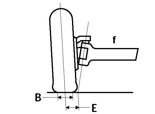 |
Using these diagrams as a rough guide, we can approximate kingpin torque (KT) by the following equation : KT = (W*(mu)*(B^2/8)+E^2)/12 [Note: Some sources state that one should double the result if the steered axle is driven.] where:
|
||||
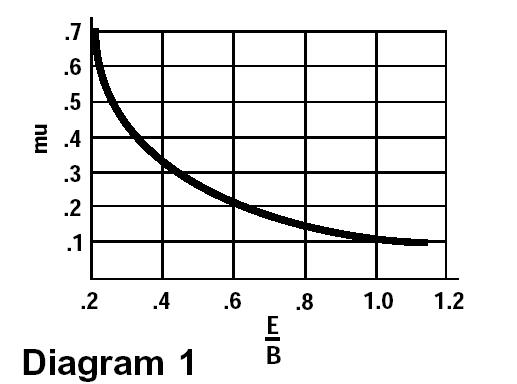 |
Chart for calculating coefficient of friction between rubber tires and dry concrete given the dimension ( E/B) or kingpin offset / nominal tire width. | ||||
So, if we plug in the following numbers, using my Wolf as an example: W=2400 lbs, mu=0.35, B=14", E=6", we come up with a result on the order of 3500 ft lbs!! Right - so you can't take that calculation to the bank, you can't design anything based on it, but hopefully it convinces you not to do a hack job and just bolt the steering arms on with any old half-inch fine thread bolts you have lying around. Which brings me to my final point about using the proper hardware, specifically the GM studs and nuts. What is the difference between a stud and a bolt? In the grossest of terms, the answer is nothing, both are merely clamping devices, as we have discussed. However, there are some important differences, which are often critical in highly stressed parts such as this. They are: A stud is frequently specified when one of the clamped-together members is an expensive cast or machined piece with internal threads - as is the case with the Dana 60 steering knuckles, especially if the assembly ever requires disassembly for inspection or maintenance, as is also the case with Dana 60 steering knuckles. This is because one wishes to avoid stripping the internal threads of the cast or machined piece at all costs - since repair may prove impossible or extremely costly. Each time an assembly is disassembled and assembled, one risks stripping or damaging the internal threads in the cast piece if a bolt is used. With a stud, one can tighten the stud in place in the cast piece, then need only remove the nut from the stud in order to dissassemble the assembly, rather than having to remove the bolt from the cast piece's internal threads; minimizing the chance of damaging the internal threads in the cast piece. Also, in an assembly highly loaded in shear, as is the case with the steering arm to knuckle joint, the stud offers us an advantage as it will be full diameter (i.e. non-threaded), right at the joint interface, where the most stress occurs, giving us maximum possible strength in the fastener, and more importantly, the tightest possible precision fit between stud and hole. We desire a tight, precision fit in order to eliminate slop and play that would contribute to a weak joint. The OTT arms are a very tight fit on the non-threaded portion of the studs for this reason. A bolt does not offer us the same advantages, because either
Finally, studs can aid us in the assembly of tight tolerance parts in a way that bolts cannot, allowing us to set the part on the studs, and then sequentially toghten down the nuts, clampnig the parts together. Using a bolt in this manned can more easily lead to cross-threading the bolt in the hole. |
|||||
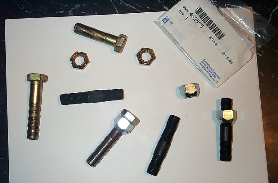 |
Even though I know all that, the fact that the proper studs (GM part number 462855) are about $14 Canadian EACH and are ONLY available from GM (since they are the only studs in existence that I know of that have fine thread on either end), caused me to try and dream up all manner of crazy home-brew ways to bolt on my steering arms, some of which you can see pictured at left, along with the correct GM studs. | ||||
It was a giant stroke of luck that at the time of this installation, my father, the genius mechanical engineer, happened to be visiting, so that I could explain each of my half-baked ideas for him to shoot down, before I had to knuckle under and go and buy the proper parts. You know that if he hadn't been, I'd have screwed up again, and a bit further down the page you'd be looking at my pics of a sheared off steering arm and three broken home-made studs and a grade 2 bolt with a lug nut welded on! Anyway, the results of our teamwork are (just in case you're tempted):
In other words - you simply have to use the GM studs and tapered nuts to do the job right. Why the taper? Well, remember what I said about wanting to avoid any slop, looseness, or misalignment in the parts, as this would eventually lead to loosening and failure of the joint, both through loss of clamping force and subsequent loss of friction, and also component fretting and eventual failure? No matter how well machined the parts are, if they are to be assembled and disassembled, there obviously has to be SOME clearance, otherwise you'd never get the parts together or apart again. The 60° taper seat in both the factory GM and the OTT steering arms, along with the tapered nuts, are the clever way of "removing" that clearance, as much as possible. As you tighten down the nut on the stud, over the steering arm, the tapered seats come together to achieve the tightest possible union that can still be disassembled easily. This is the same reason your wheels and lug nuts also use a 60° taper. |
|||||
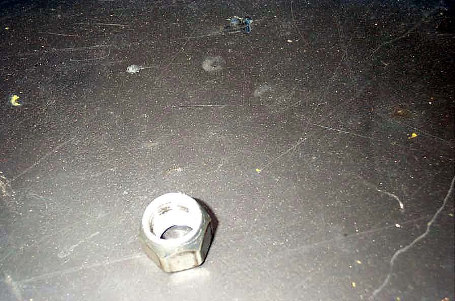 |
Speaking of lug nuts. One more "gotcha" I wish I had know about in advance. DO NOT use cheap parts-store 1/2"-20 lug nuts. yes they will have the correct taper (maybe - depending on quality control I guess), BUT they will NOT be hard or strong enough. When you attempt to tighten them down on the very hard GM studs, you will quickly and easily strip the soft, crappy threads out of them. Ask me how I know, the pic to the left should be a giant hint! (sorry for the lousy quality). You should use the GM nuts, or if you must, a hard, high quality nut made in the US/CAN/UK/AUS by a reputable manufacturer. | ||||
OK, allow me to summarize, and proceed with the actual installation. ***Use only the specified factory GM studs and tapered nuts for installation of these steering arms*** Phew - let's get on with it then! |
|||||
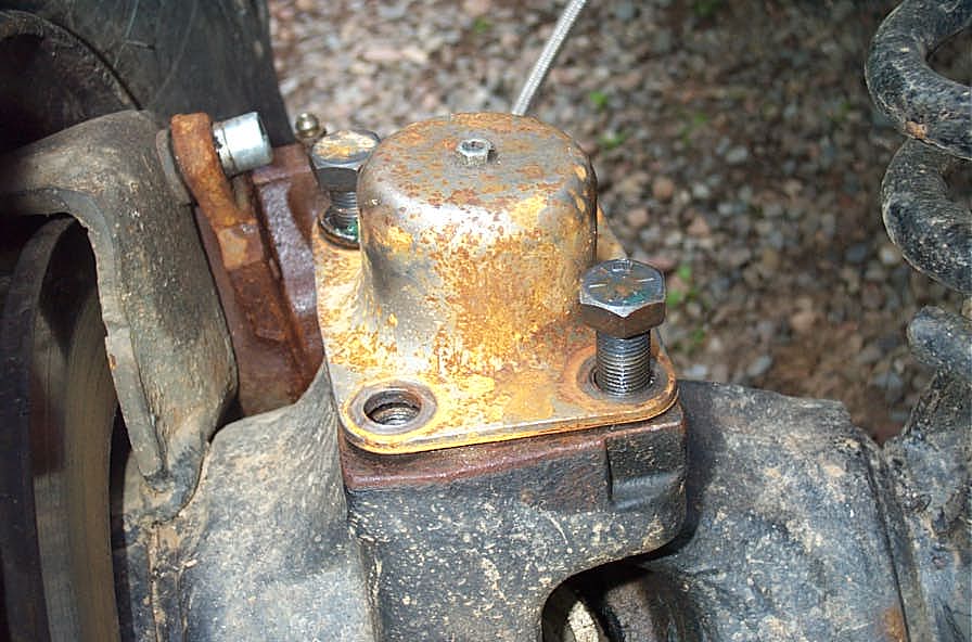 |
Step one, remove existing kingpin cap (or stock steering arm) bolts / studs. If they've been there for a while, significant force / heat may be required. See my kingpin rebuild article for more. Loosen each one a little at a time, as the spring tension beneath the cap can be quite high and pop the cap off with some force.Remove the cap, spring, spring retainer, and gasket, and clean the mating surface at the top of the knuckle. Also clean out the threaded holes in the knuckle. I had recently run a tap through mine during a kingpin rebuild, so merely blew them clean with compressed air. You may want to run a tap down. |
||||
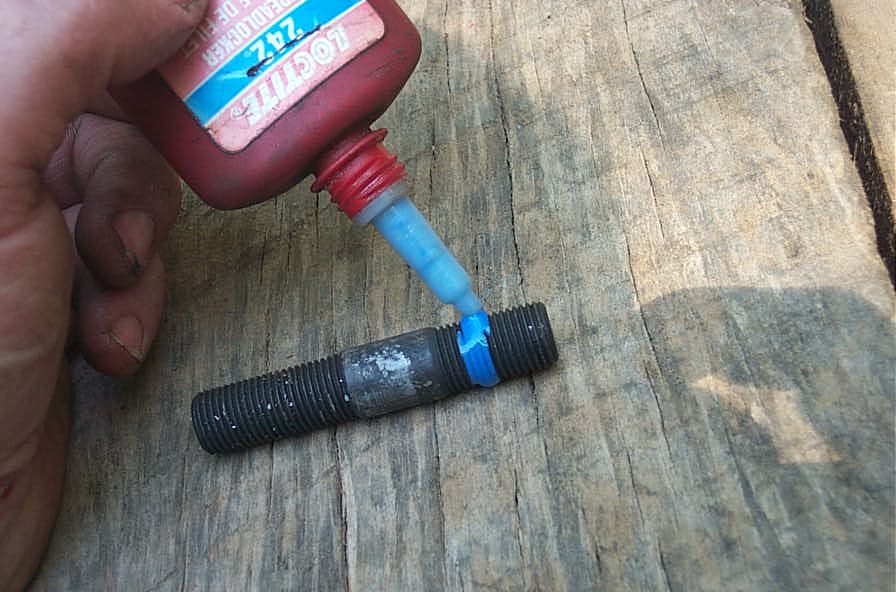 |
Apply thread locking compound to the SHORT end of the studs. I chose medium strength Loctite Blue (242). | ||||
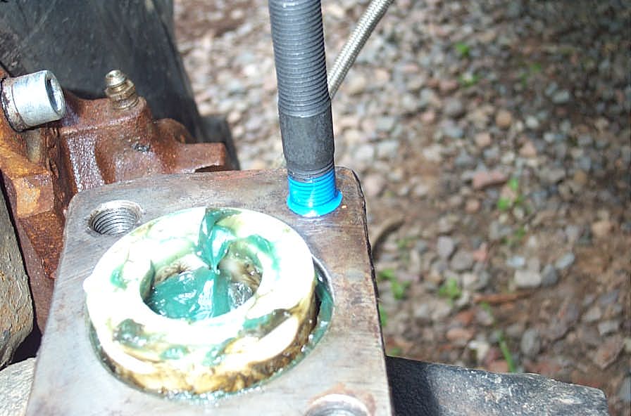 |
Install the studs in the knuckle, preferably torqued to 80 ft .lbs. This may be hard to measure if you don't have a fancy stud-installing tool. | ||||
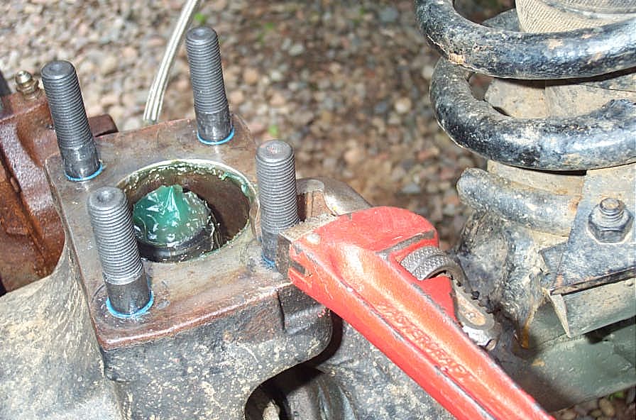 |
I snugged them down tight with a pipe wrench. | ||||
 |
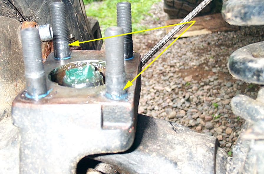
Initially, I had tried running a nut on the stud till it bottomed against the unthreaded shank, but all that did when I came to tighten the studs into the knuckle was strip the threads out of the nut. I don't know what the GM studs are made of, but it is pretty damn hard and tough. This can be seen in the front left stud in this pic, where you can see the debris of the destroyed nut around the threads just above the unthreaded shank. The stud itself remained untouched. | ||||
 |
You do, however, have to be careful with using a pipe wrench or similar tool when installing studs, as the serrated jaws of the tool can mar the stud. I suffered this slightly in 2 out of the 8 studs I installed, but it was very minor. | ||||
 |
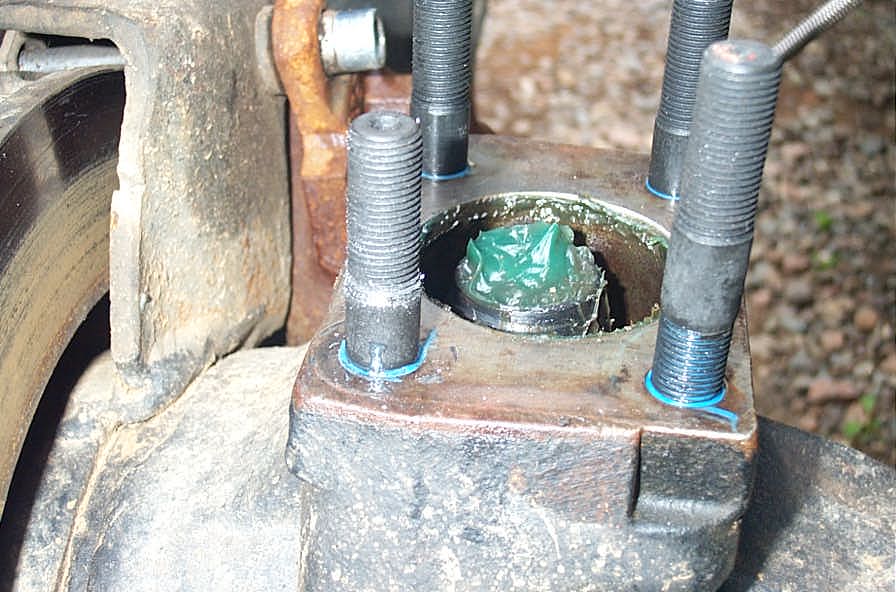
When all the studs are installed, wipe away excess thread locking compound from the knuckle face, grease both sides of a new gasket, and install the gasket over the studs. | ||||
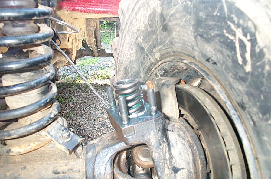 |
Place the spring retainer and spring back in place on top of the kingpin bushing. | ||||
 |
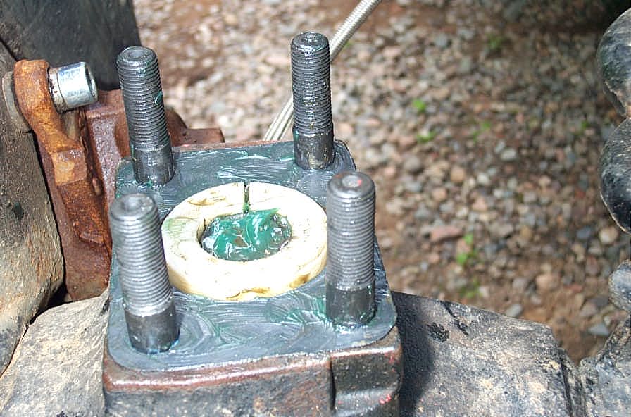
Then place the OTT steering arm over the studs. It will not drop all the way on, one because of the kingpin spring, but also because of the tight tolerances between stud and holes. This is where I first learned of my SNAFU of painting the inside of the mounting holes. It was so tight, I removed the spring, and still I couldn't really get it on - the clearances are just that tight. This is, of course, a very good thing when it comes to the ultimate strength of the assembly. I removed the arm and carefully removed the paint from inside the holes, then re-installed it. | ||||
 |
The arm only just fits over the studs, and with the spring, there is almost no room to even start the nuts, so I used a couple of clamps to cinch it down a bit so that I could start the nuts on the studs. | ||||
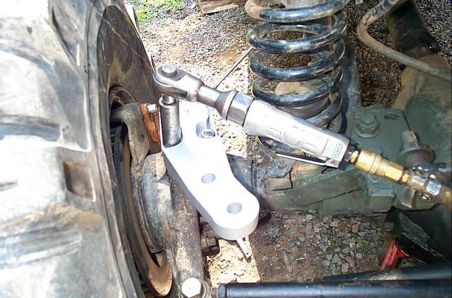 |
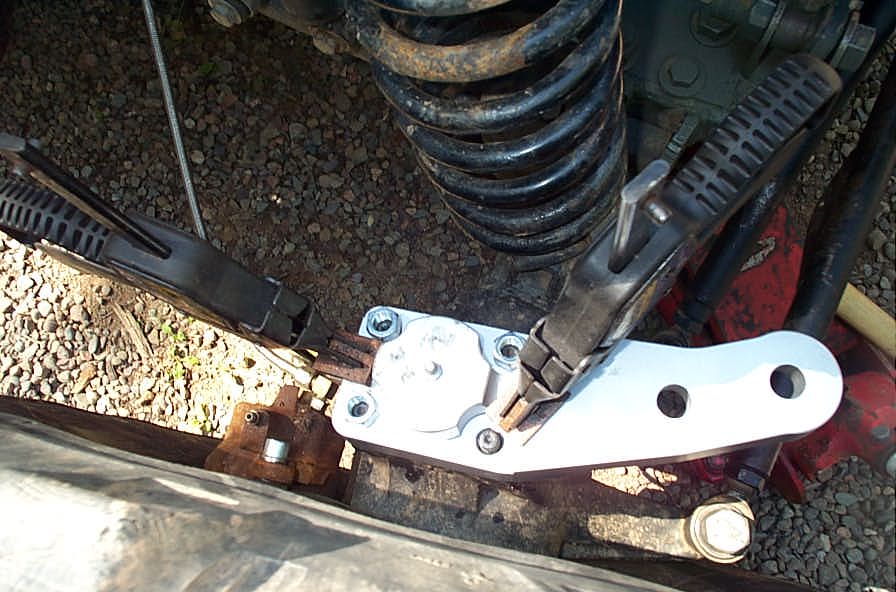
Once the nuts are started, I used an air ratchet (do not use an impact tool - the hammering action is not good at this point) to sequentially tighten down the nuts, which will eventually clamp the steering arm down over the studs and in place on the knuckle. Factory final torque spec is 80 ft/lbs. | ||||
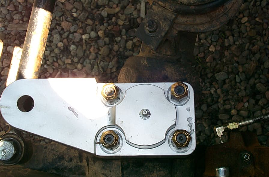 |
Knowing that I darn well did not want them to loosen, I had what I thought was a bright idea after I had tightened down the tapered nuts. I thought I would install Bowman grade 8 locking nuts (deformed thread style, often called a "stover" nut) on top of the tapered nuts. The only thing was, I believe there turned out to be insufficient threads of the stud exposed to fully engage the ovalated threads at the top of the locking nut that actually provide the locking action. There are therefore dubious anti-loosening properties added by doing what I did. I left them in place however, and consoled myself with the fact that they at least protect the exposed threads. | ||||
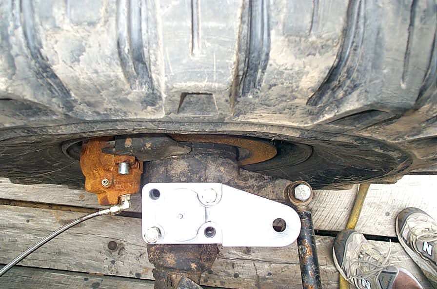
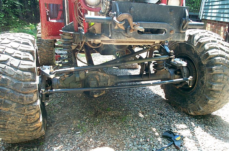
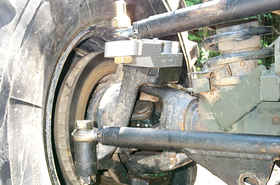
I fully expect they will loosen and fall off! And with me being Mr Bean of the workshop - at least one will probably get sucked into the carburetor! Note the marked up paint from the clamp used during installation. A by-product of not painting them early enough so that the paint could harden before I had to install them the day before a giant annual 3 day wheelin fest! I expect you are beginning to see why I remarked earlier that I really would have appreciated some sort of instruction sheet - even for what appear to be "bolt on" parts. At least one should be included if these things are going to be sold to bumbling dim-witted three-thumbed garage monkeys like me! Of course, being a military man - I have been rigorously indoctrinated with the mantra "Don't bring me problems, bring me solutions". So, with that in mind, I have created an instruction sheet for the OTT High Clearance Steering Arms, (it's really just a simplified version of this article) that may be viewed or printed from right here by current or prospective OTT customers. You guys at OTT: Ben, Rick, Chris - feel free to save and print these and then include them in the box when you sell 'em - anything to help out my fellow Canucks! It is available in PDF The following pics show the "final" installation in the Wolf, at least the first iteration. I was unable to move the tie rod up to the arms, as it would have then passed directly through where my track bar currently is. As I had hastily decided to install them the day before a major 3 day event, I simply didn't have time for the required re-design to make everything work perfectly. However, I was able to separate the tie rod and drag link, so at least I can bend the tie rod and just flip it around. Also, the drag link is raised way up so there is no longer any interference between it and the track bar bracket, so I am no longer at risk of tearing the track bar off again.
|
|||||
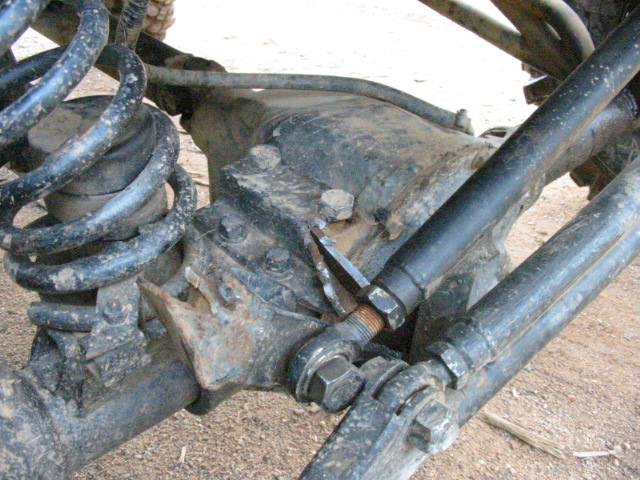
 |
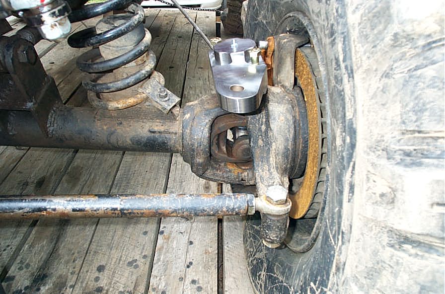
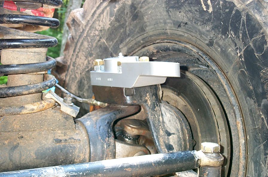
I flogged the whole rig hard for 3 days at our annual Rockathon event, including the new steering arms. This picture clearly illustrates how much better protected everything will be when I get the whole steering linkage moved up to the OTT arms. As it turns out, my steering box finally blew its guts out on the third day - something I had been expecting / fearing for quite some time. This has moved up my plan for full hydraulic steering, so I shall probably next update this article when I get that all rigged up, so you can see how the OTT arms work with full hydro. At the end of the season I shall also remove the arms and check the roundness of the mounting holes, and report the results here; as this will tell us a lot about the long term durability of the arms. |
||||
|
|||||
|
Sources: OTT Industries#56080 1690 Nanaimo Street rick@ottindustries.com |
|