 |
Turn Key 525HP LS2 By Bill "BillaVista" Ansell |
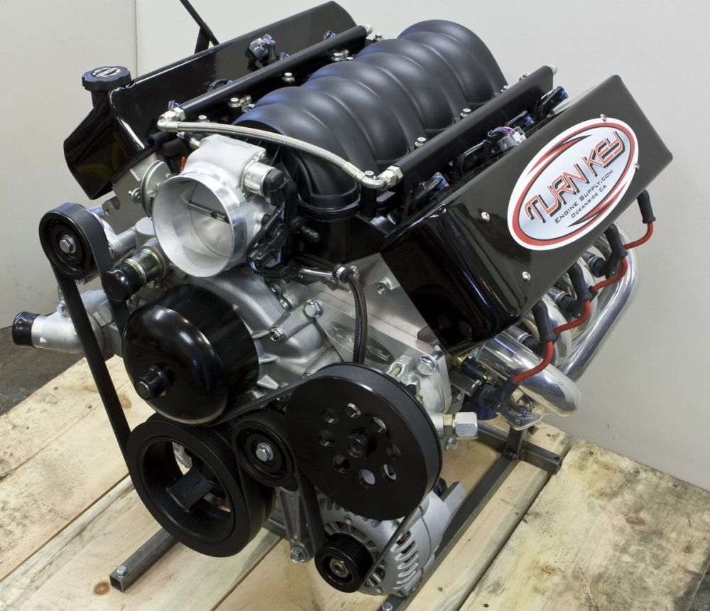
IntroductionWelcome to a visual tour-de-force examination of one of the best engines you can put in an off-road rig - the awesome Turn Key Engine Supply LS2 510. Based on the fourth-generation GM LS2, Turn Key Engine Supply of Oceanside, CA start with a factory deep-skirt cast 319-T5 aluminum alloy block, custom-build it with a handful of go-fast goodies for performance and reliability, finish it with your choice of front accessory packages, and top the whole thing off with custom built marine-grade wiring harness and Turn Key calibrated Delphi MEFI-4 marine fuel injection. The result is heart-stopping performance combined with bulletproof simplicity and reliability. And if that's not enough, Turn Key supply the motor in a package that includes, everything, and I mean everything you need. |
 |
||
There's a lot to cover so I've laid out this article in the following sections:
and we'll conclude with some seriously eye-candy in the form of some beautiful photography of the TKLS2, courtesy of my good friend Lonny Handwork. If you're not yet up to speed on your Gen III and Gen IV GM engines, you may wish to start with my LS-Primer - Part 1 or LS-Primer - Part 2. For the rest of us - let's dig in!
LS2 BasicsFirst built in 2005 to power the Chevrolet Corvette, the LS2 was the first of the fourth-generation (or Gen IV) GM small-block V8 engines. Over the past few years it has been used in Chevrolet Corvette, Pontiac GTO, Cadillac CTS-V, Chevrolet SSR, Chevrolet TrailBlazer SS, and is still used today in the Saab 9-7X Aero. The LS2 is a longitudinal, 90°, 6.0L, V8, pushrod, cam-in-block, all-aluminum, small-block engine with overhead valves (2 per cylinder), hydraulic roller valvetrain, cracked & hot-forged steel alloy powder metal connecting rods, 6-bolt cross-bolted powder metal mains, and composite intake manifold. It features sequential multi-port fuel injection (SFI) and distributorless coil-near-plug ignition. The LS2 displaces 5970cc (364.3 ci) with a bore of 101.6mm and a stroke of 92mm. Valves are stainless-steel on the intake and exhaust side. The block is a deep-skirt cast 319-T5 aluminum alloy piece, the cylinder heads are cast aluminum and use replicated (identical or symmetrical) ports, and the crank is cast nodular iron, internally balanced, with undercut and rolled fillet journals. Compression is 10.9:1. Stock power is 390-400 hp, but Turn Key replace the cam, pistons, rod bolts and valve springs, add a custom 90mm throttle-body and billet aluminum fuel rails, and work a little custom tuning / calibration magic to produce a package that is conservatively rated at 510hp. Why an LS2?Why pick an LS2? Well, the quick answer is, it offers the most and best bang for the buck - superbly engineered reliable power in a light, compact, package. But I'm getting ahead of myself. First, why a Gen III/IV GM V8? I'm a huge fan of GM/Chevy V8's. Since over 100 million have been produced since 1955, I might be on to something - and I don't think I'm alone! For me, nothing but a V8 will do - I don't care how light and quick-revving a little 4-cylinder is, I don't care how compact a V6 is, and although I appreciate the tech in air-cooled VW motors - none of these are for me. It's gotta be a V8 - and NOBODY does V8's better than GM. So, when my old 1970's small-block Chevy finally gave out I knew I wanted another GM V8 - but which one? Well, first, I knew I wanted a Gen III or IV. Why? Easy - imagine a perfect V8: it would be light, compact, smooth, quiet, powerful (producing at least 1hp per cu. in.), have a broad, flat torque curve, be reliable and durable, have good fuel economy and low emissions, and have huge aftermarket support. It would feature advanced sequential fuel injection, distributorless ignition with a coil for each plug, be able to rev high yet pull hard from low RPM, have a quiet, efficient, reliable valvetrain, smooth idle, and be internally balanced. And while we're at it, it should do all that on pump gas and normally aspirated, so I don't have to bother with the expense, complexity, maintenance, and more challenging packaging of turbos or superchargers. In short - it would be a third- or fourth-generation GM V8 because, stacked up against that criteria, there's not another engine that can touch the Gen III/IV's. Oh, and if that isn't enough, ideally, it would have all that and retain a bellhousing pattern that would allow the use of virtually any manual or automatic transmission from old-school 4-speed gear grinders to the latest 6-speed electronically controlled automatics - which the Gen III/IV's do! But which of the many Gen III/IV's to choose? After much research, most of which is documented in my LS-Primer - Part 1 and LS-Primer - Part 2., the LS2 emerged as my choice because the LS2, as a Gen IV, incorporates many important refinements and improvements over the original Gen III motors but without the unnecessary (for my application) complexity of the advanced features such as Active Fuel Management (also known as "displacement on demand") and Variable Valve Timing (aka "cam phasing") found in other Gen IV motors. Notable improvements in the Gen IV LS2 over Gen III motors like the LS1 and LS6, include:
All that and, well, to be honest, I couldn't afford an LS3, LS7, or LS9 - so a kick-ass LS2 it was! Why Turn Key Engine Supply?Well, in a sense, the answer to that is the subject of the rest of this article. Certainly the answer should be obvious by the end - but the short version is - if nobody does V8's like GM, nobody does aftermarket GM V8's like Turn Key! But don't take my word for it - take a look at this: Part 1 - Unpack & Overview |
|||
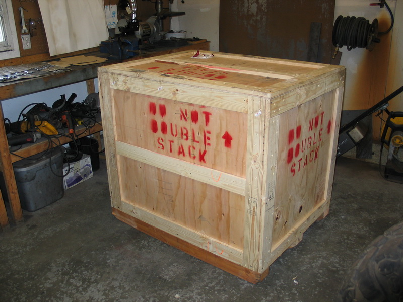 |
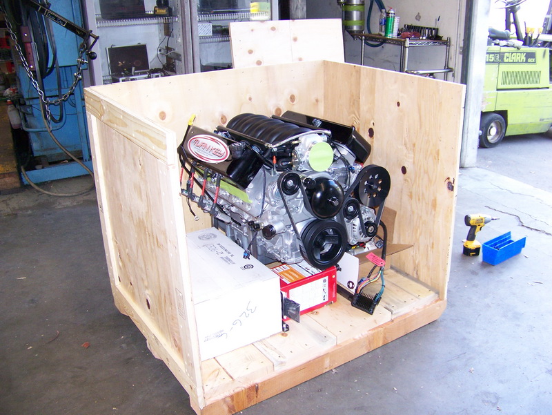
Here's how it arrives, all buttoned up in its own custom crate. | ||||||||||||||||||||||||||||||||||||||||||||||||||||||||||||||||||||||||||||
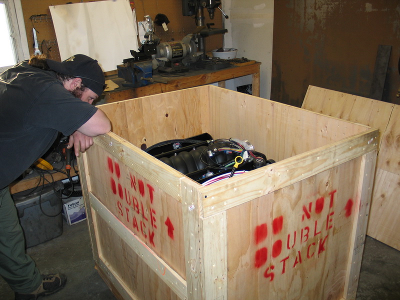 |
I snapped this pic of my buddy Andrew, who had come over to help me unload the crate, just after we lifted the top off. We were both a little stunned, having never seem anything quite like it before. |
||||||||||||||||||||||||||||||||||||||||||||||||||||||||||||||||||||||||||||
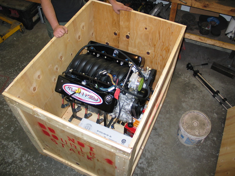 |
There it was, shining like a pearl in an oyster. We spent a lot of time just saying "Wow!", and "Oh my God!" |
||||||||||||||||||||||||||||||||||||||||||||||||||||||||||||||||||||||||||||
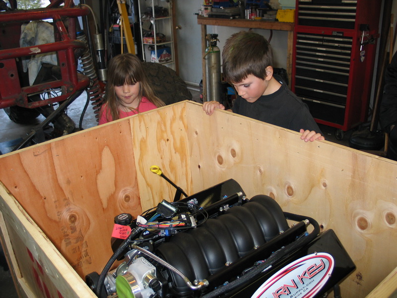 |
I figured I better show the kids why they're going to need to get a job if they want to go to college! | ||||||||||||||||||||||||||||||||||||||||||||||||||||||||||||||||||||||||||||
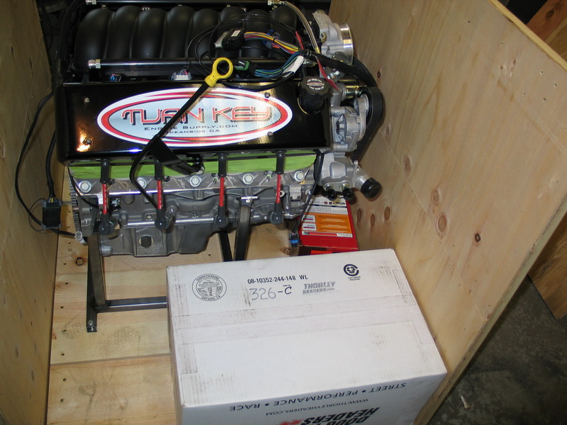 |
Neatly tucked in the crate are the the K&N air filter and Doug Thorley headers... | ||||||||||||||||||||||||||||||||||||||||||||||||||||||||||||||||||||||||||||
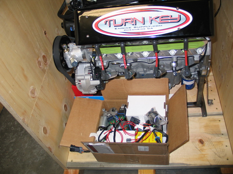 |
...and a box containing all the other parts needed, from fuel pump to starter motor. We'll go over all of these in detail later. | ||||||||||||||||||||||||||||||||||||||||||||||||||||||||||||||||||||||||||||
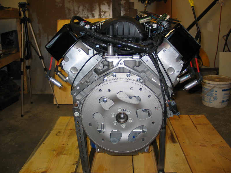 |
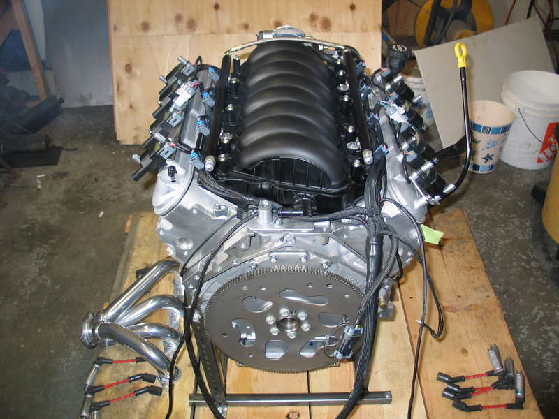
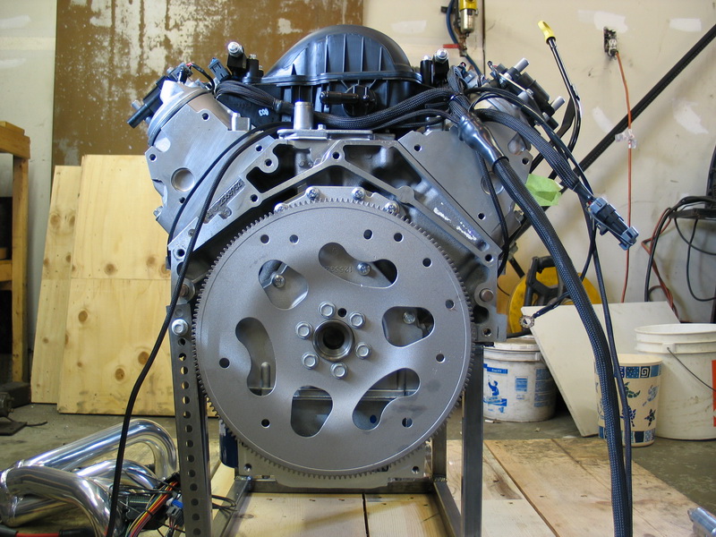
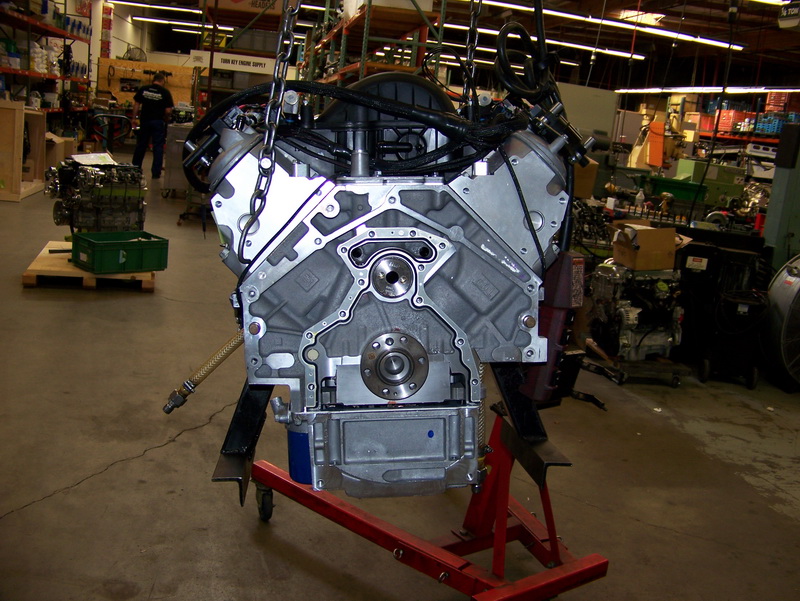
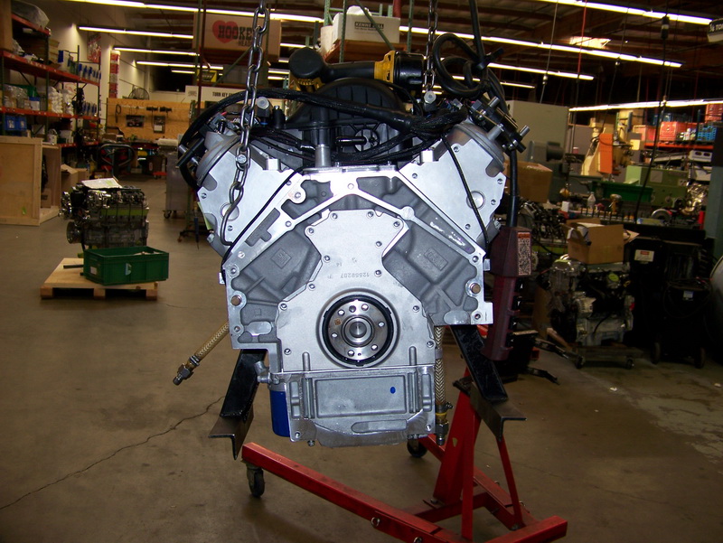
Rear view of the motor with the crate disassembled. The flywheel is the "dished" version from a "truck" 5.3L Gen III engine that Turn Key dual-drill so that it can accommodate both early GM transmissions (like the TH400 and TH350) and later transmissions like the 4L60E and 4L85E. |
||||||||||||||||||||||||||||||||||||||||||||||||||||||||||||||||||||||||||||
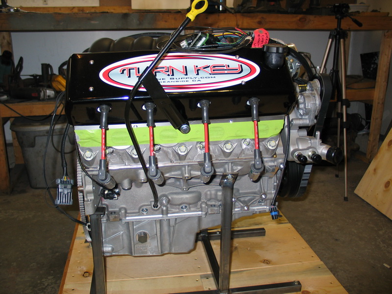 |
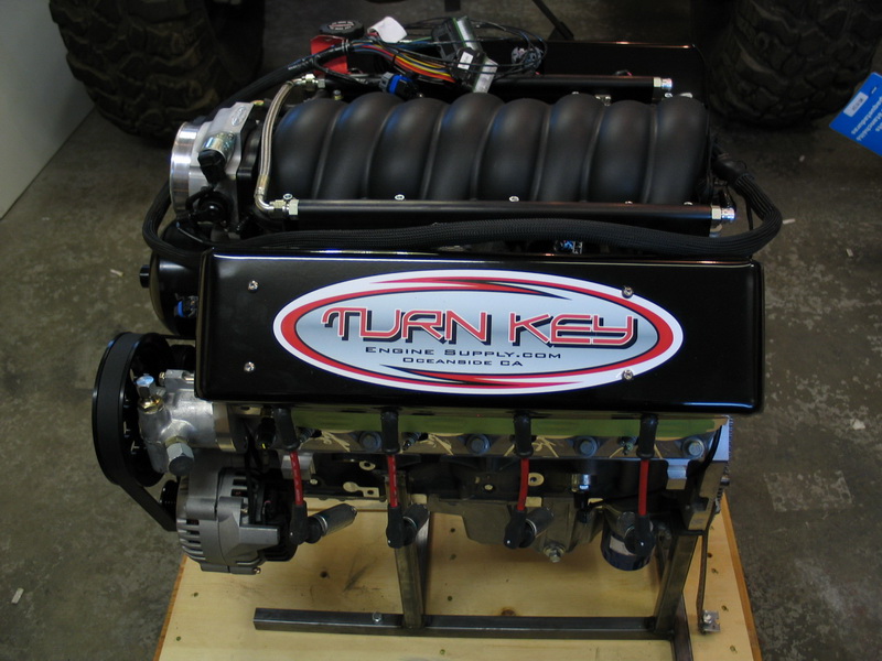
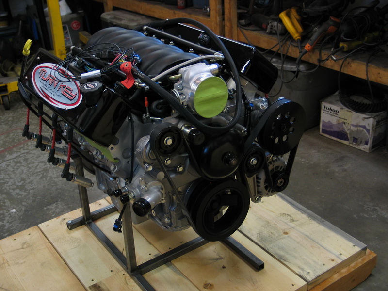
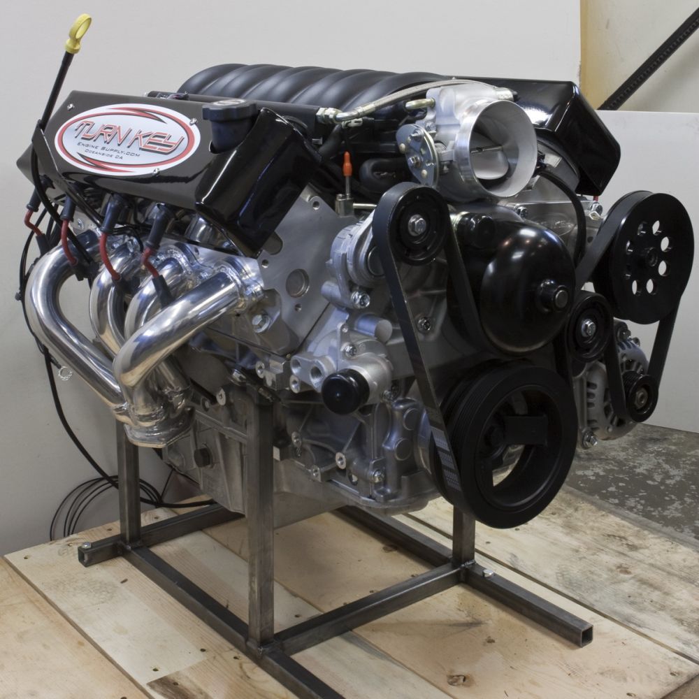
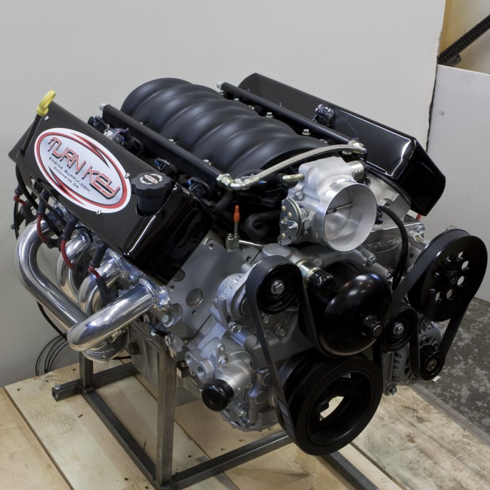
Right side of the motor. Note the super-short plug wires of the coil-near-plug ignition system and the cool custom stand the motor ships on. |
||||||||||||||||||||||||||||||||||||||||||||||||||||||||||||||||||||||||||||
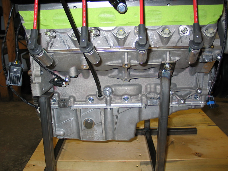 |
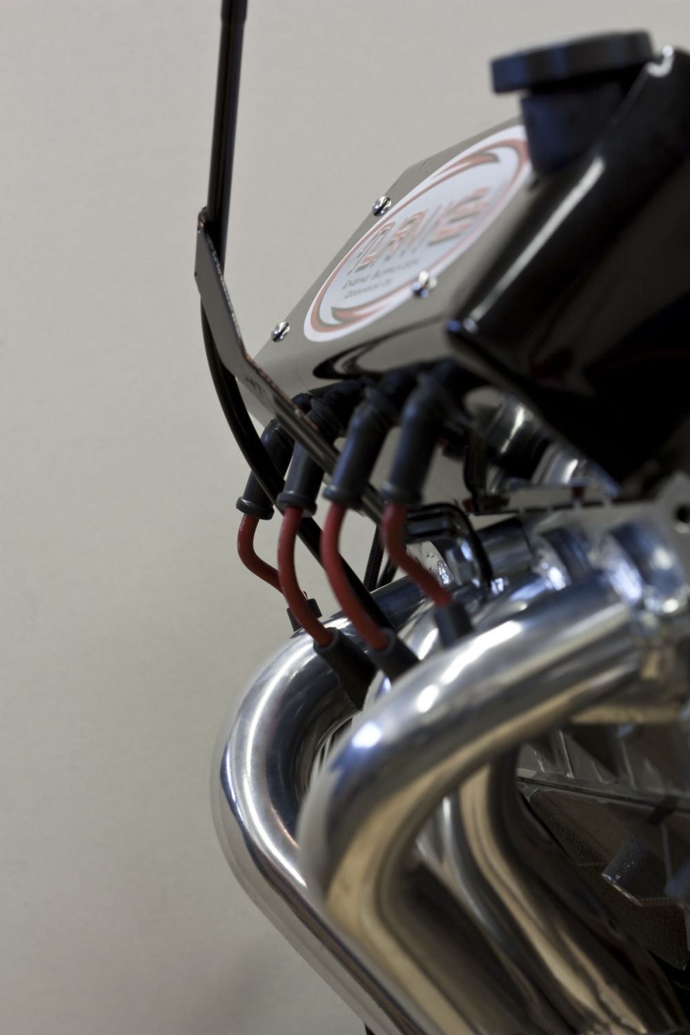
Close-up of the right side. | ||||||||||||||||||||||||||||||||||||||||||||||||||||||||||||||||||||||||||||
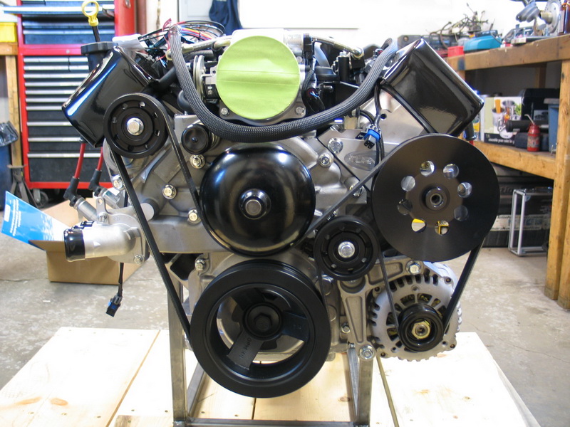 |
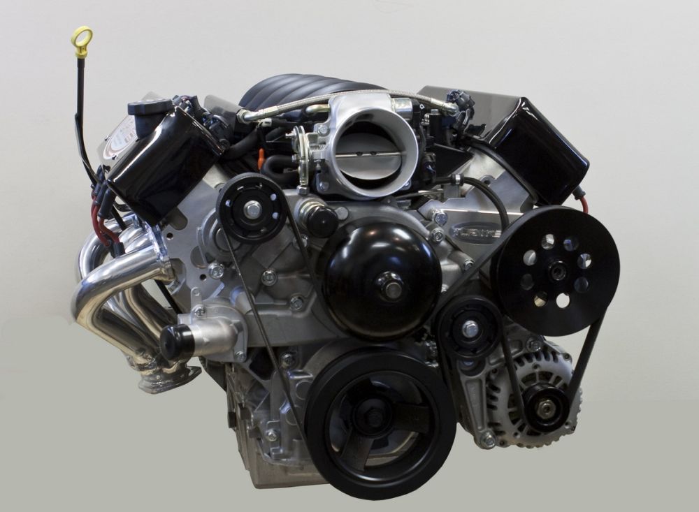
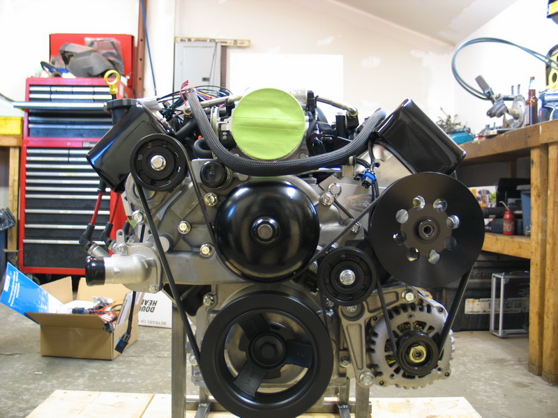
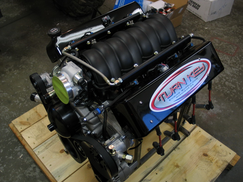
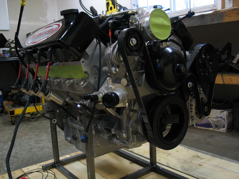
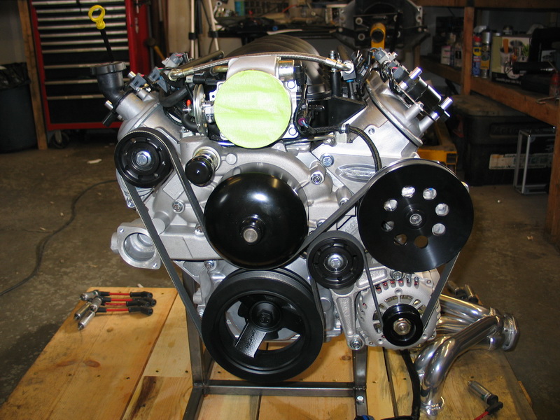
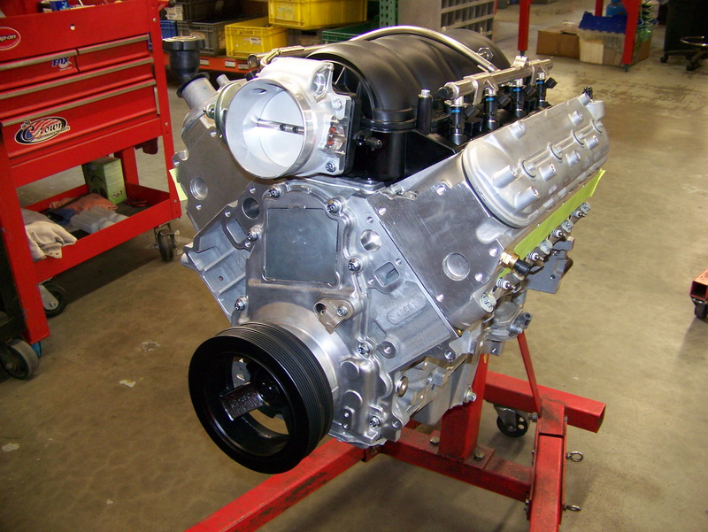
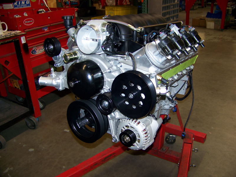
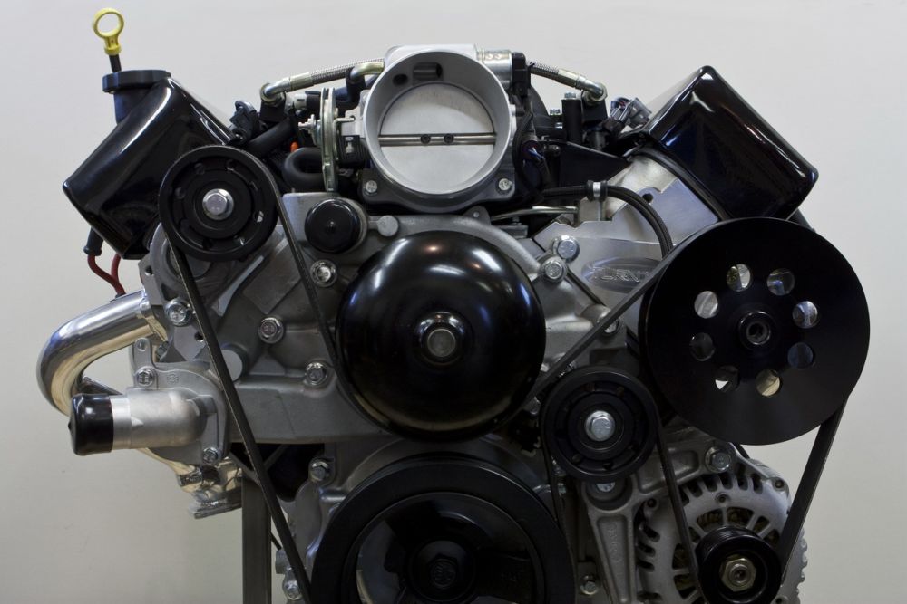
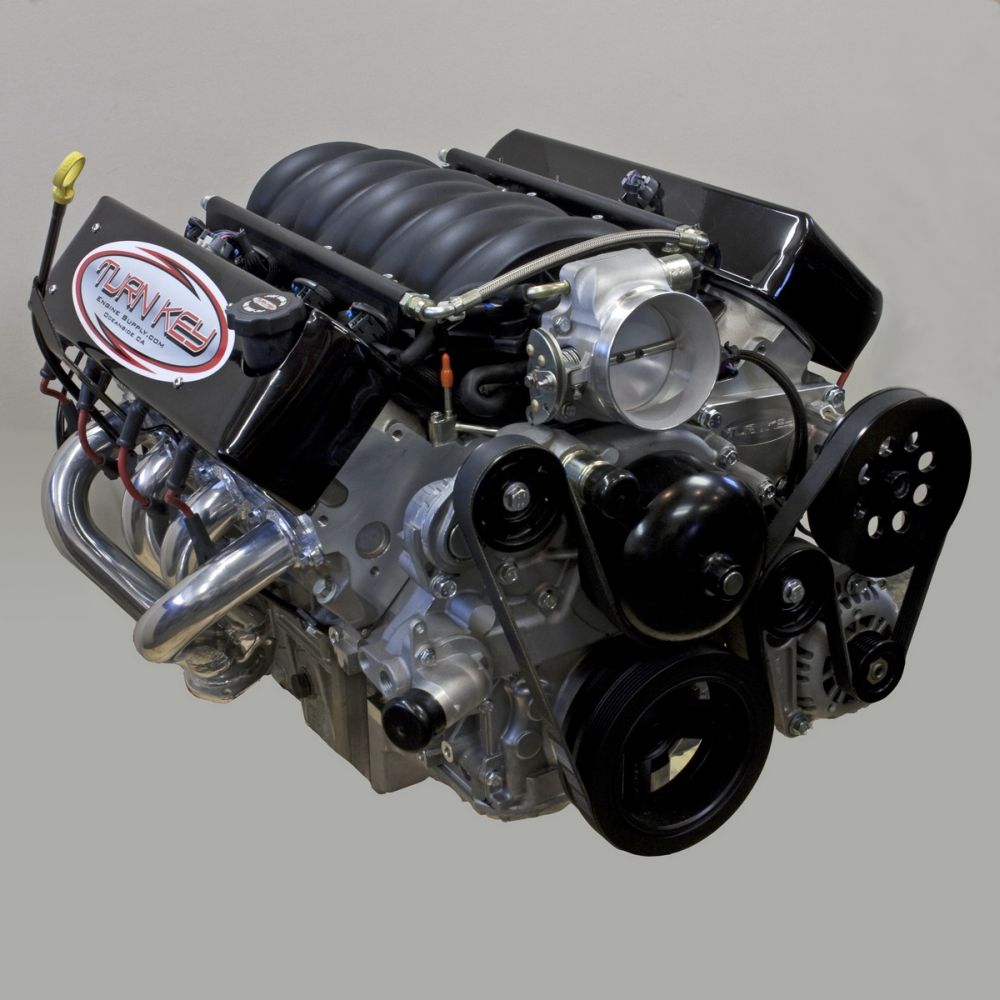
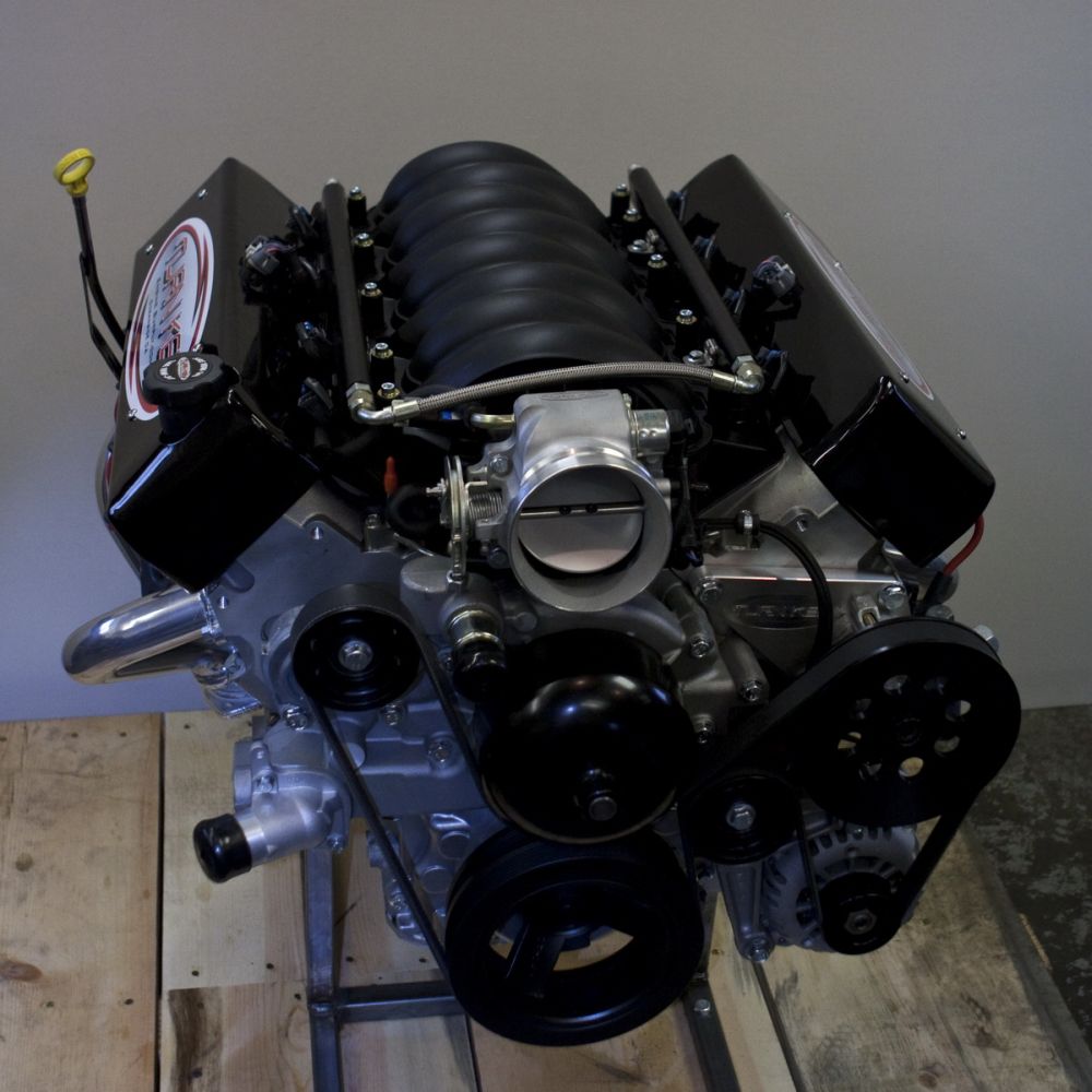
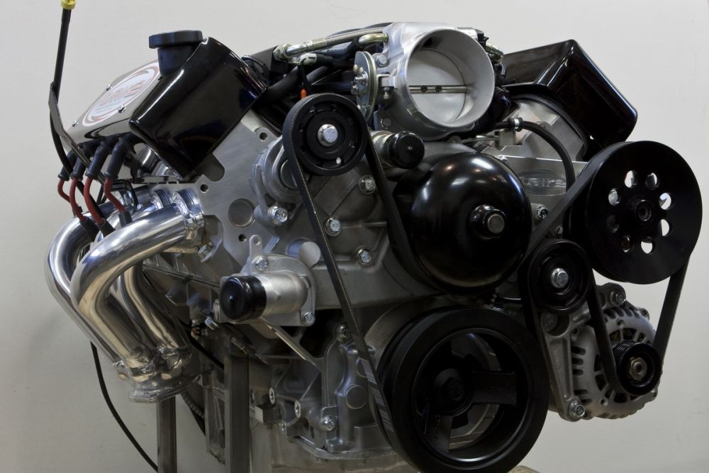
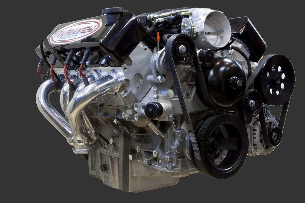
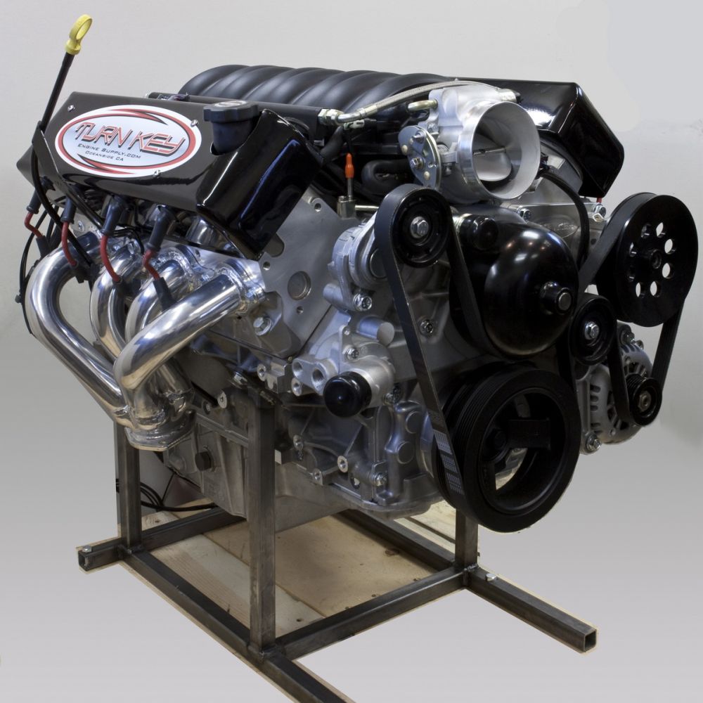
Front view of the motor showing the front accessory drive package. The accessory package is based on a Gen III (1999-2002) Chevrolet Camaro. This makes replacement parts much more affordable, since putting the word "Corvette" before a part name is second only to saying "marine" or "aviation" in terms of raising the price on otherwise functionally identical parts. |
||||||||||||||||||||||||||||||||||||||||||||||||||||||||||||||||||||||||||||
 |
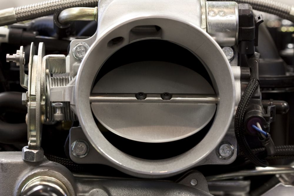
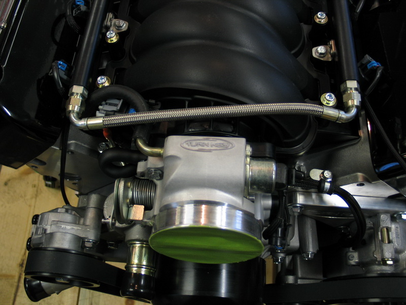
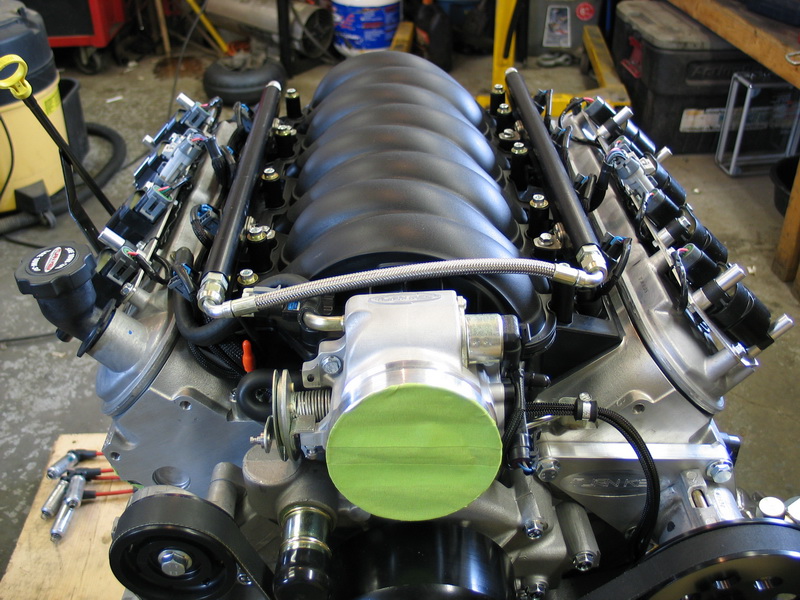
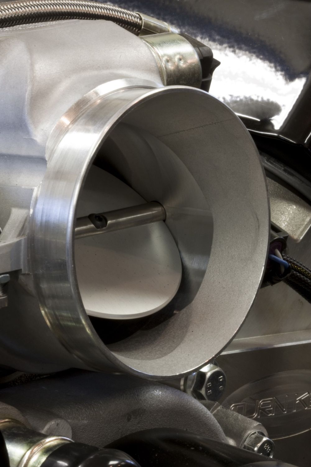
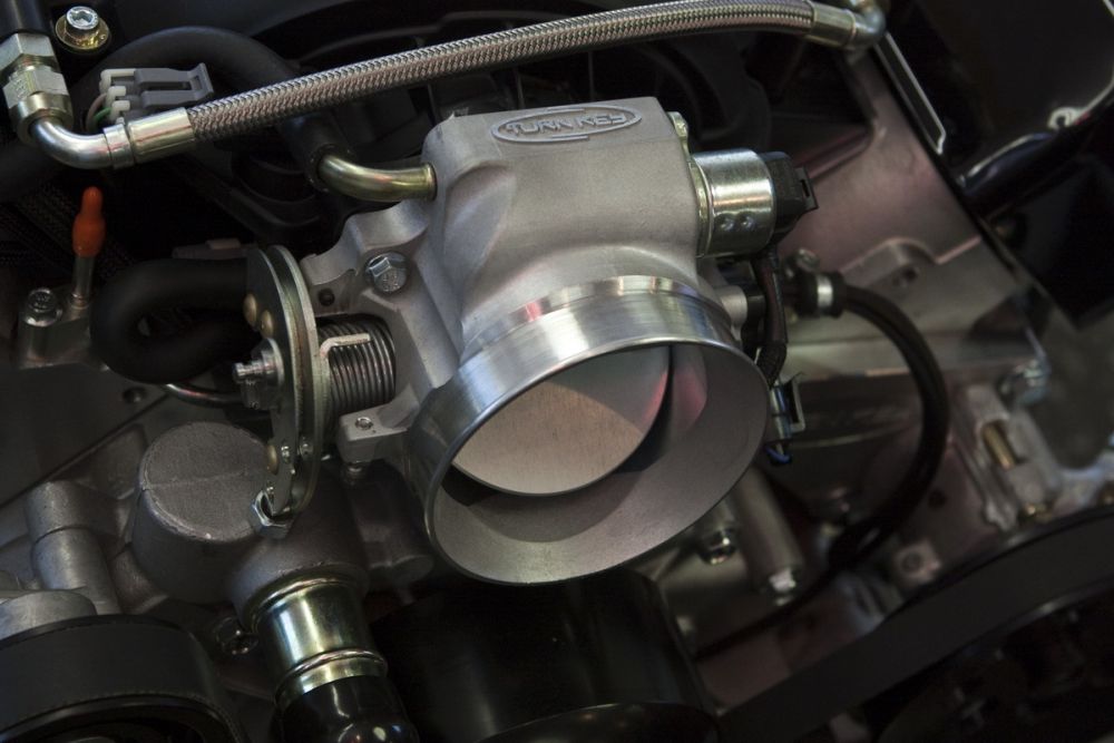
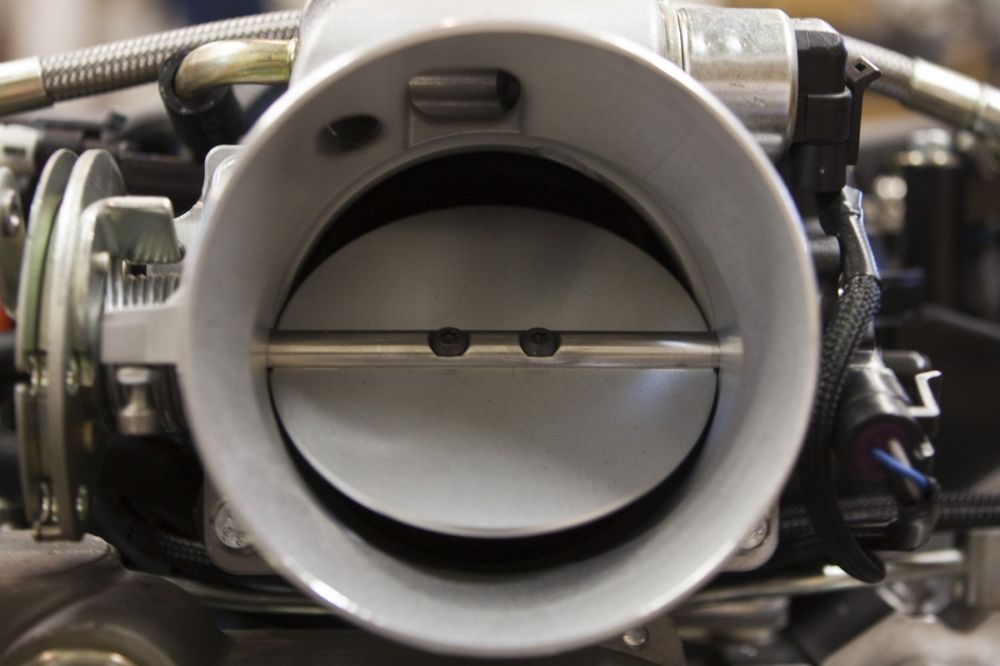
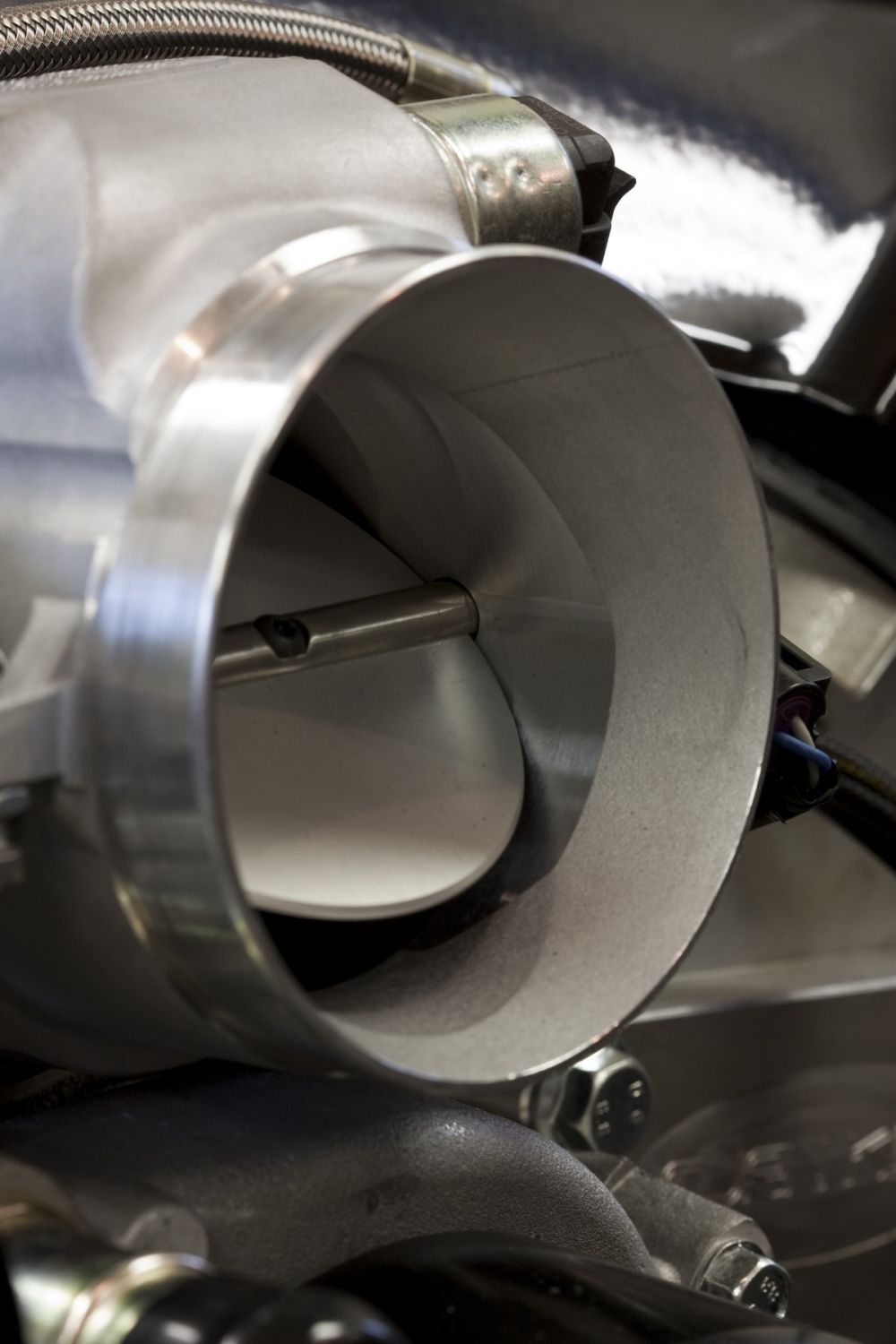
The throttle-body is a custom Turn Key piece that uses the simple, reliable, conventional cable-operated throttle as opposed to the stock LS2's Electronic Throttle Control (ETC) or "throttle-by-wire" system. | ||||||||||||||||||||||||||||||||||||||||||||||||||||||||||||||||||||||||||||
 |
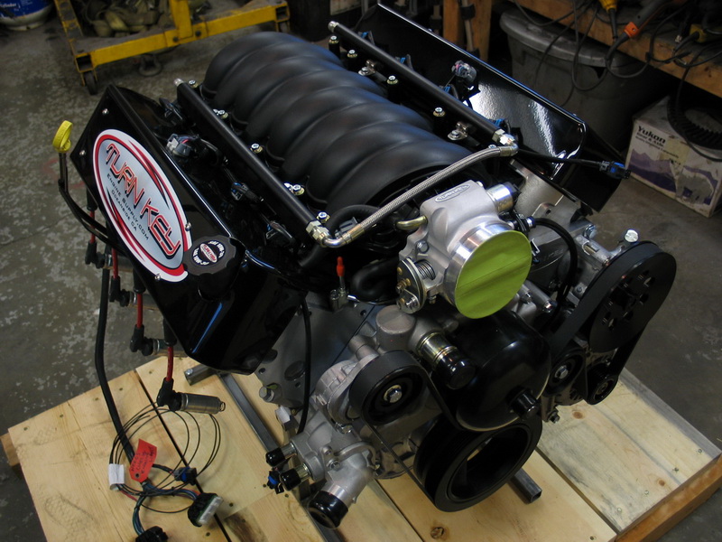
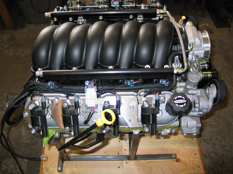
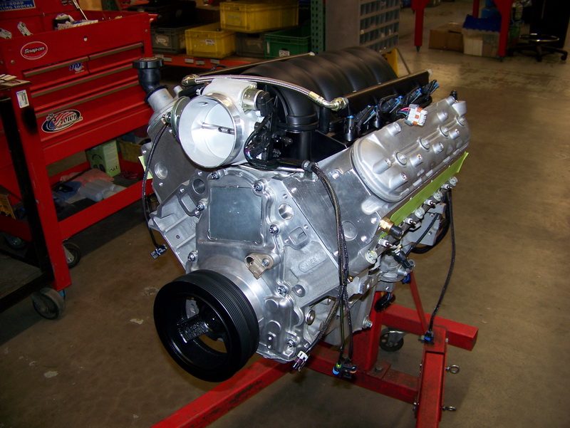
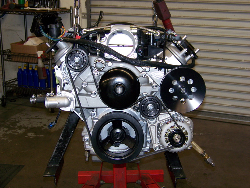
Left side of the engine. Note the cool powder-coated, stainless-steel, coil covers. The alternator is a 120 amp unit, from 2002 Camaro. The power-steering pump is a high-pressure 1450 psi Howe "TC" style pump with -10AN inlet and -06AN outlet. |
||||||||||||||||||||||||||||||||||||||||||||||||||||||||||||||||||||||||||||
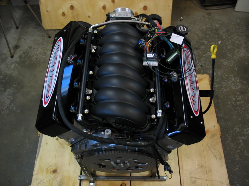 |
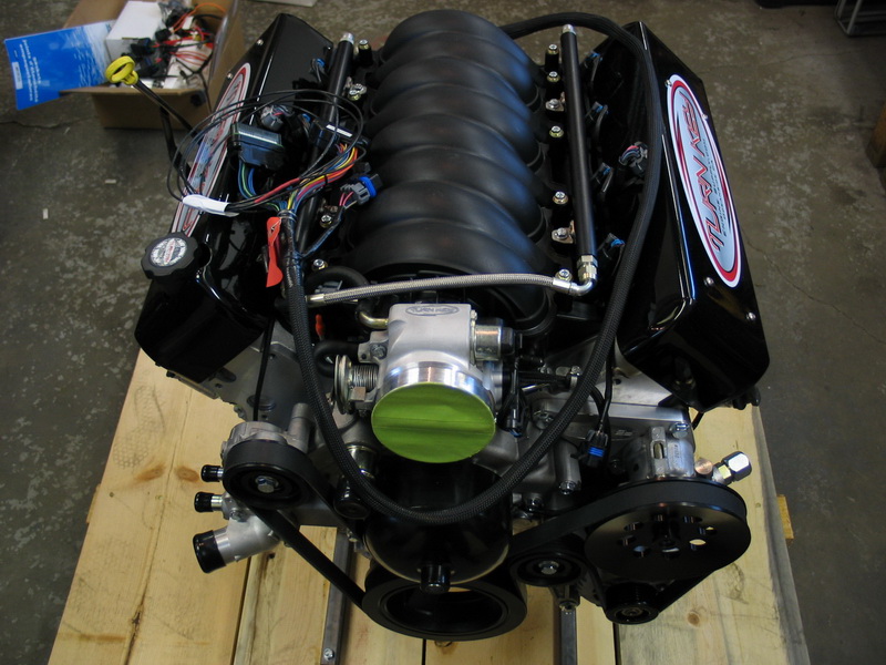
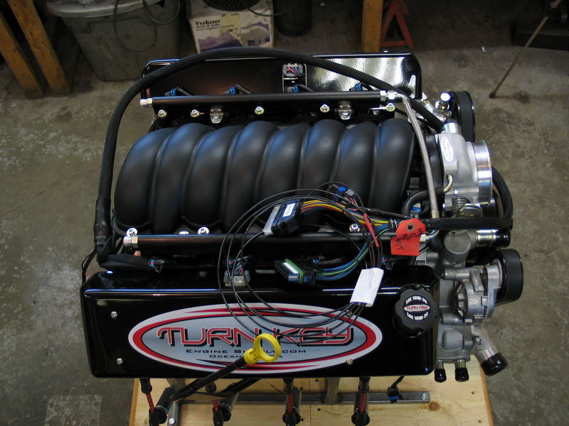
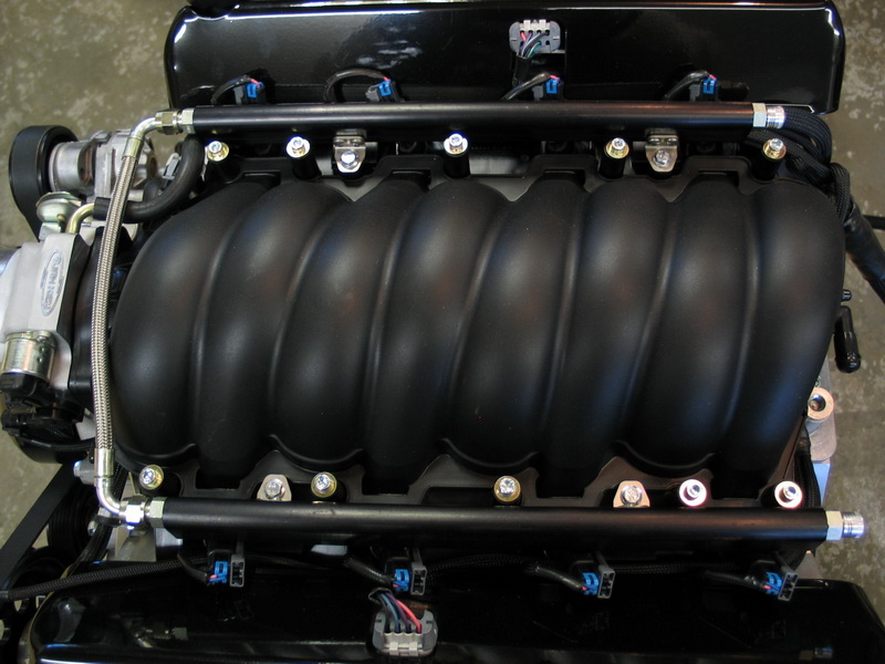
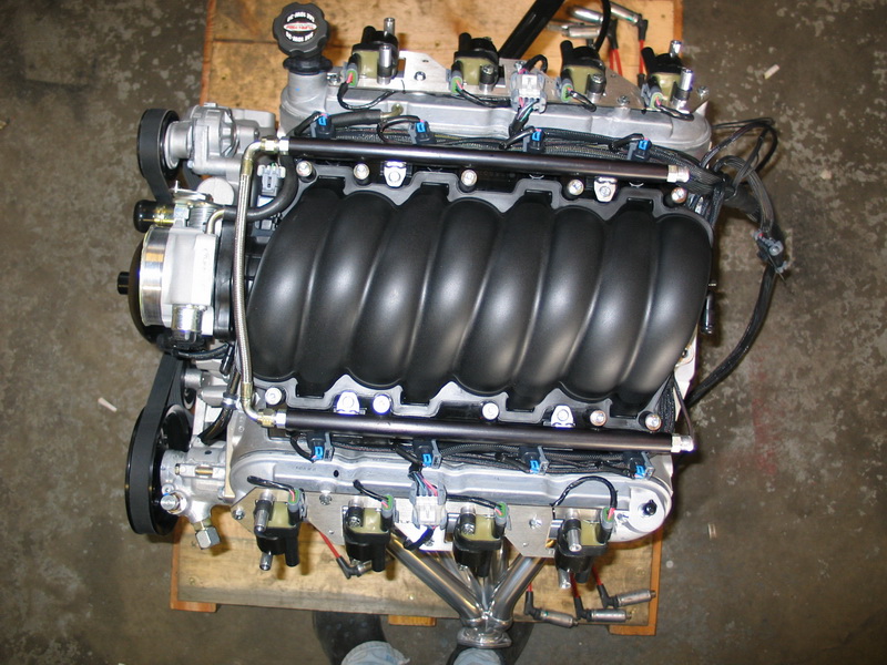
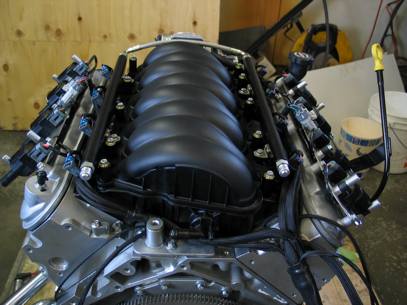
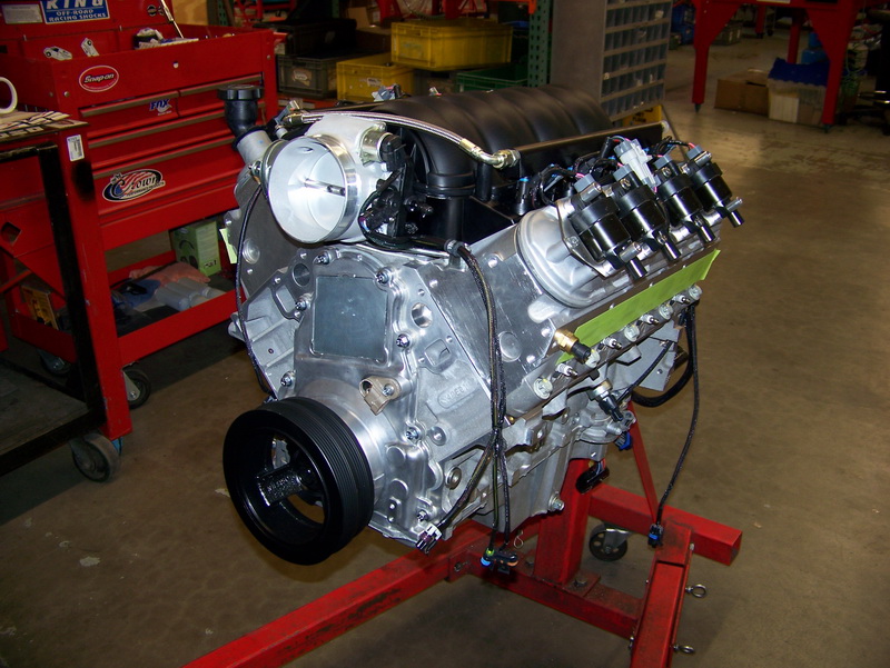
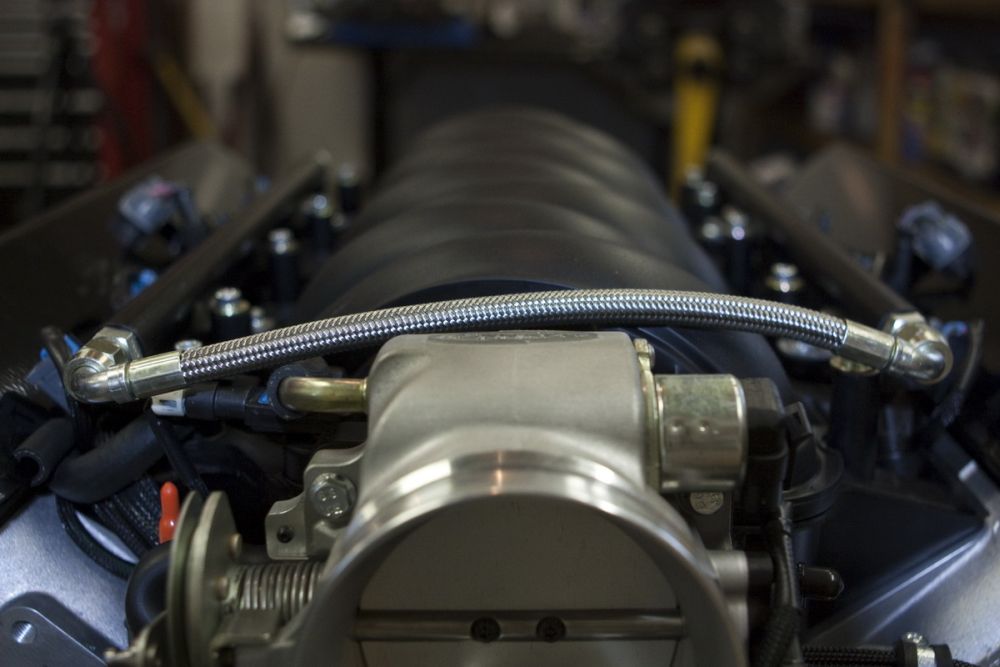
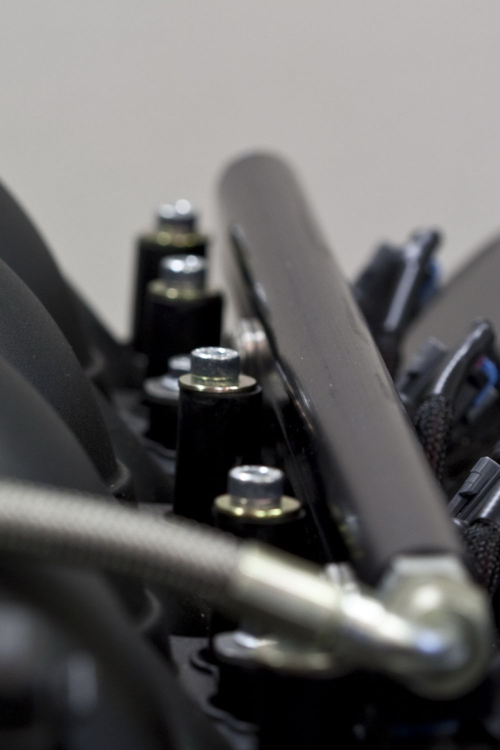
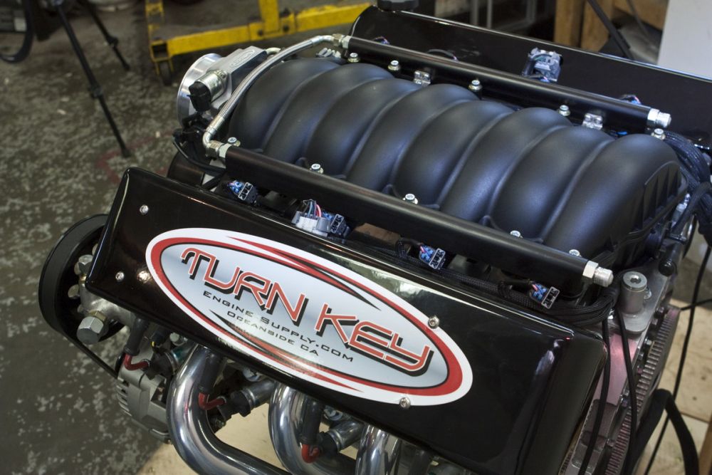
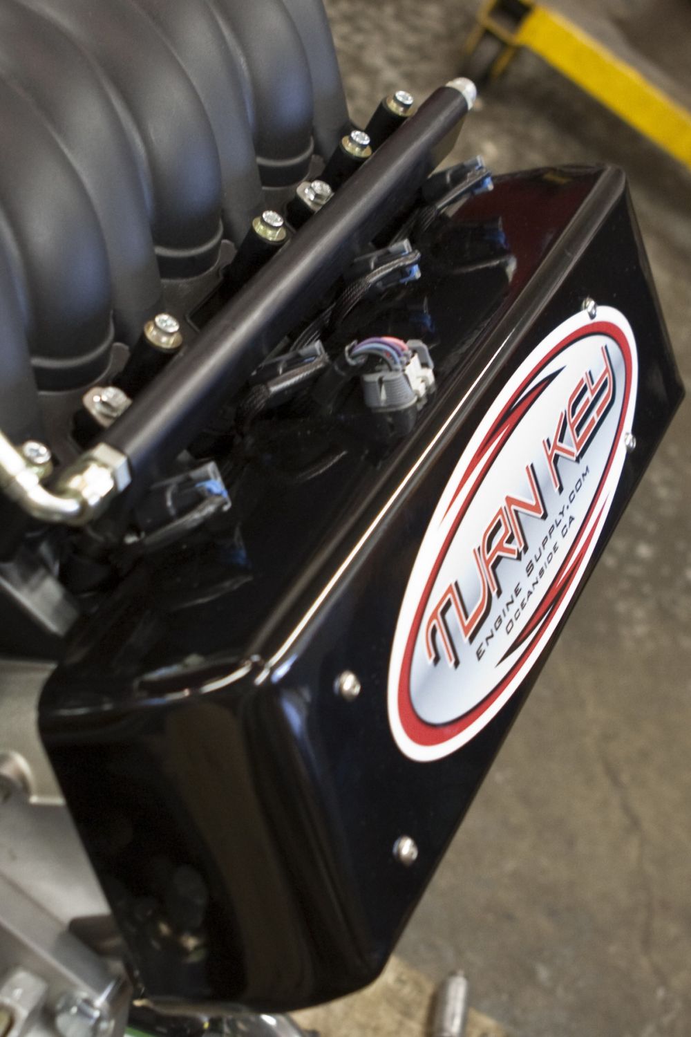
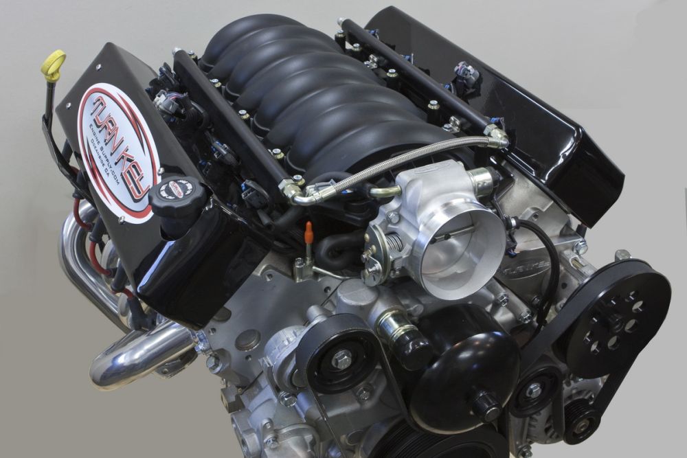
Top view of the motor. Note the custom billet-aluminum fuel rails. |
||||||||||||||||||||||||||||||||||||||||||||||||||||||||||||||||||||||||||||
 |
Right side from above. | ||||||||||||||||||||||||||||||||||||||||||||||||||||||||||||||||||||||||||||
 |
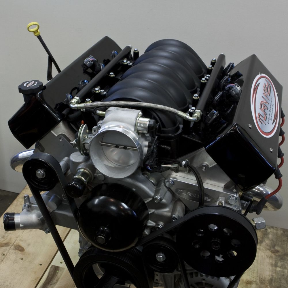
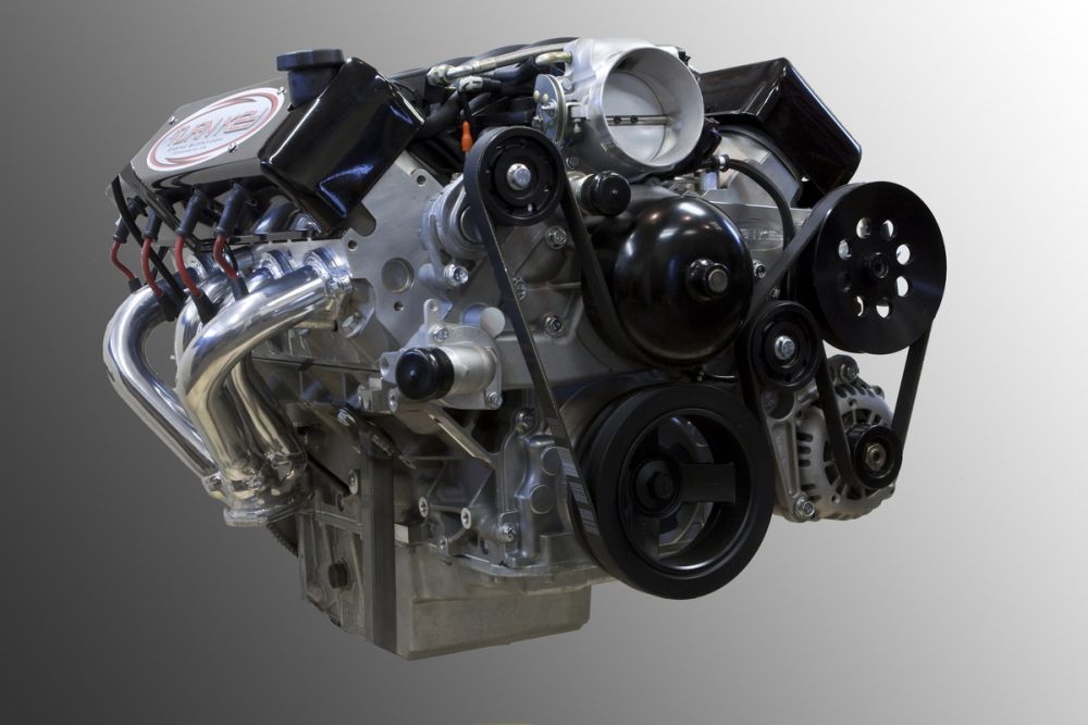
Right-front 3/4 view. | ||||||||||||||||||||||||||||||||||||||||||||||||||||||||||||||||||||||||||||
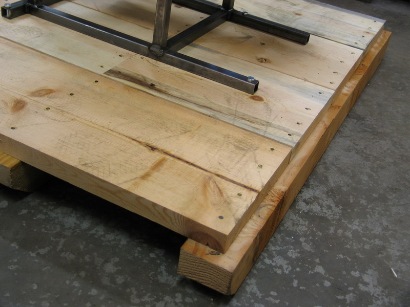 |
Check out how heavy-duty and well-built the crate is! | ||||||||||||||||||||||||||||||||||||||||||||||||||||||||||||||||||||||||||||
 |
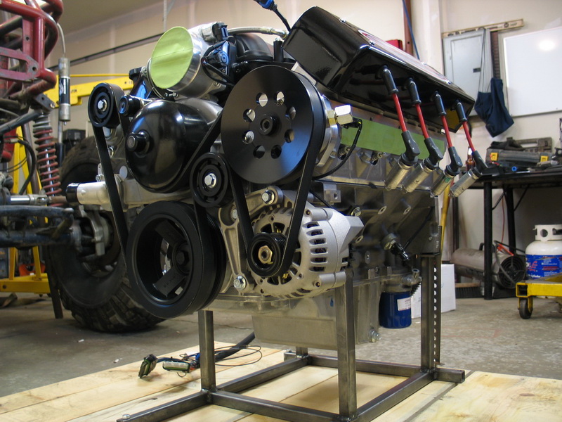
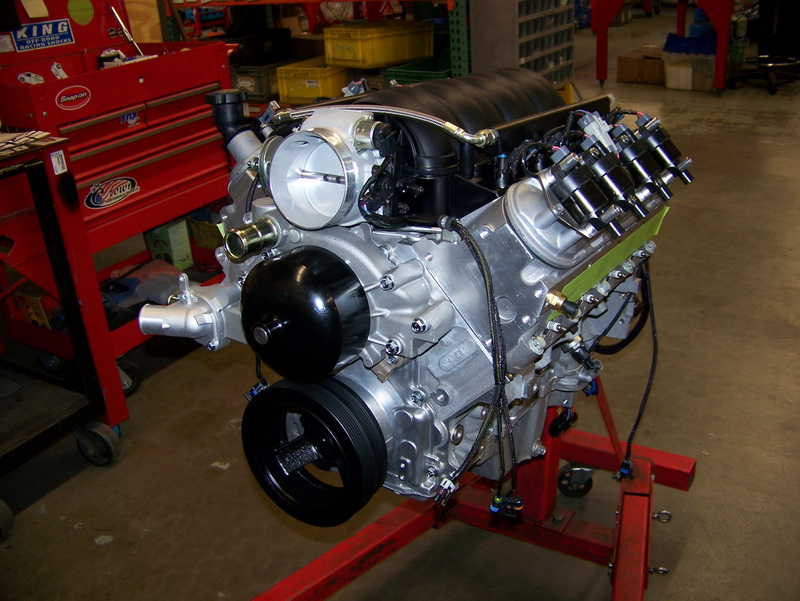
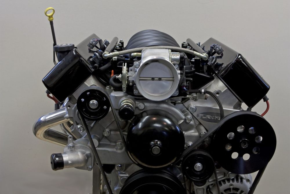
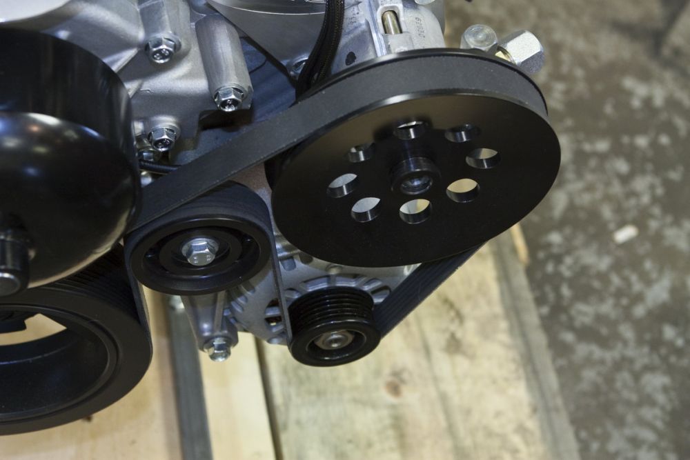
Another view of the front accessories. The water pump and alternator are '02 Camaro. The PS pump is Howe, and the arrangement is custom Turn Key using custom solid-mount brackets. The Gen III/IV accessory drive system was developed with low noise and vibration in mind. Turn Key can custom mount accessories in any arrangement to suit the customer's needs. |
||||||||||||||||||||||||||||||||||||||||||||||||||||||||||||||||||||||||||||
 |
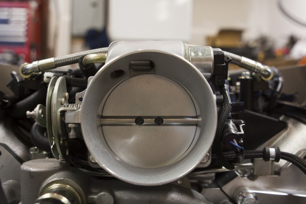
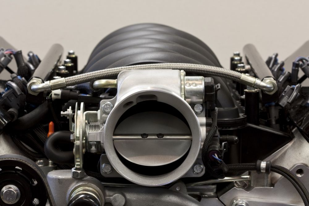
Top of the custom Turn Key 90mm, cable-controlled throttle body. | ||||||||||||||||||||||||||||||||||||||||||||||||||||||||||||||||||||||||||||
 |
Custom Turn Key aluminum power steering pump mounting bracket. | ||||||||||||||||||||||||||||||||||||||||||||||||||||||||||||||||||||||||||||
 |
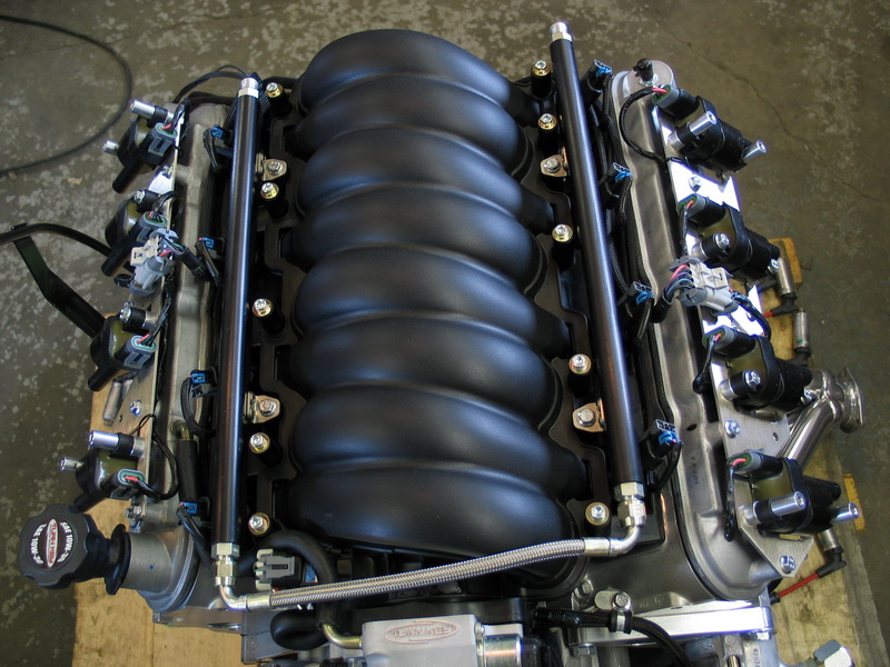
The very cool LS2 composite intake manifold. A lot of work was done by GM to improve the LS2's intake over the Gen III designs. Runner shape and geometry and a larger bell-mouth were incorporated to improve flow and optimize the intake for the LS2's 6.0L displacement. The intake is also constructed using a trick vibration welding technique where composite plastic pieces are molded separately and then assembled, held in position, and vibrated until the parts melt from friction and weld themselves together. The LS2 intake manifold is made from a glass-filled, composite polymer called Nylon 6. |
||||||||||||||||||||||||||||||||||||||||||||||||||||||||||||||||||||||||||||
 |
Throttle body. | ||||||||||||||||||||||||||||||||||||||||||||||||||||||||||||||||||||||||||||
 |
Coil cover. | ||||||||||||||||||||||||||||||||||||||||||||||||||||||||||||||||||||||||||||
 |
Left-front 3/4 view from above. | ||||||||||||||||||||||||||||||||||||||||||||||||||||||||||||||||||||||||||||
 |
Left-front 3/4 view from below. | ||||||||||||||||||||||||||||||||||||||||||||||||||||||||||||||||||||||||||||
 |
Right-front 3/4 view from above. | ||||||||||||||||||||||||||||||||||||||||||||||||||||||||||||||||||||||||||||
 |
Right-front 3/4 view from below. | ||||||||||||||||||||||||||||||||||||||||||||||||||||||||||||||||||||||||||||
Part 2 - Coil Covers OffThe following pics show the motor with the coil covers removed. The coil covers are not a structural part and are mostly cosmetic (the individual coils mounted on the rocker covers aren't the most attractive thing) although they do help to keep water and mud off the coils, rocker covers, and wiring. |
|||||||||||||||||||||||||||||||||||||||||||||||||||||||||||||||||||||||||||||
 |
Right-side with the coil covers removed. |
||||||||||||||||||||||||||||||||||||||||||||||||||||||||||||||||||||||||||||
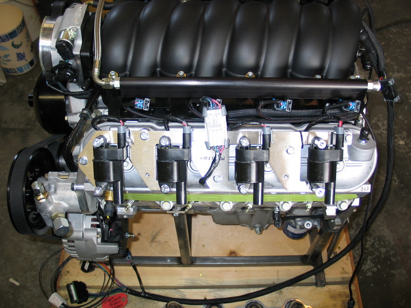 |
Left-side with the coil covers removed. Note the individual coil packs. |
||||||||||||||||||||||||||||||||||||||||||||||||||||||||||||||||||||||||||||
 |
Rear-view with the coil covers removed. | ||||||||||||||||||||||||||||||||||||||||||||||||||||||||||||||||||||||||||||
 |
Top view with the coil covers removed. | ||||||||||||||||||||||||||||||||||||||||||||||||||||||||||||||||||||||||||||
 |
Front view with the coil covers removed. | ||||||||||||||||||||||||||||||||||||||||||||||||||||||||||||||||||||||||||||
 |
Lower-right with the coil covers removed. | ||||||||||||||||||||||||||||||||||||||||||||||||||||||||||||||||||||||||||||
 |
Lower-left with the coil covers removed. | ||||||||||||||||||||||||||||||||||||||||||||||||||||||||||||||||||||||||||||
 |
This rear-view with the coil covers removed shows how low-profile the actual rocker covers are. | ||||||||||||||||||||||||||||||||||||||||||||||||||||||||||||||||||||||||||||
 |
Top-rear view with the coil covers removed. | ||||||||||||||||||||||||||||||||||||||||||||||||||||||||||||||||||||||||||||
 |
Top-front view with the coil covers removed. | ||||||||||||||||||||||||||||||||||||||||||||||||||||||||||||||||||||||||||||
 |
Top view with the coil covers removed. Note the clear view of the fuel injectors. |
||||||||||||||||||||||||||||||||||||||||||||||||||||||||||||||||||||||||||||
Specs:Here are the specs on my Turn Key LS2:
Part 3 - Motor Being BuiltNow we take a step back and have a detailed look at the parts and the actual building of the motor. The Turn Key "510" LS2 uses a combination of stock and custom internal parts. Stock power is 390-400 hp, but Turn Key replace the cam, pistons, rod bolts and valve springs, add a custom 90mm throttle-body and billet aluminum fuel rails, and work a little custom tuning / calibration magic to produce a package that is conservatively rated at 510hp. |
|||||||||||||||||||||||||||||||||||||||||||||||||||||||||||||||||||||||||||||
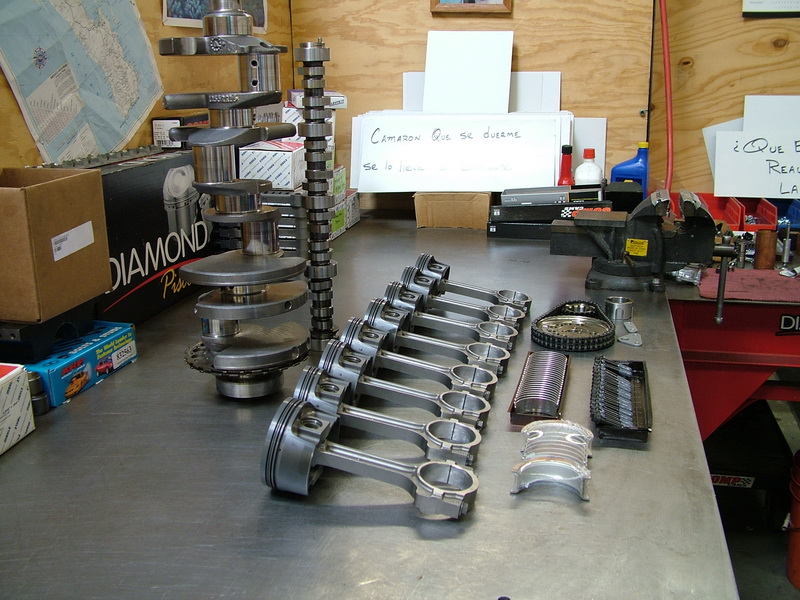 |
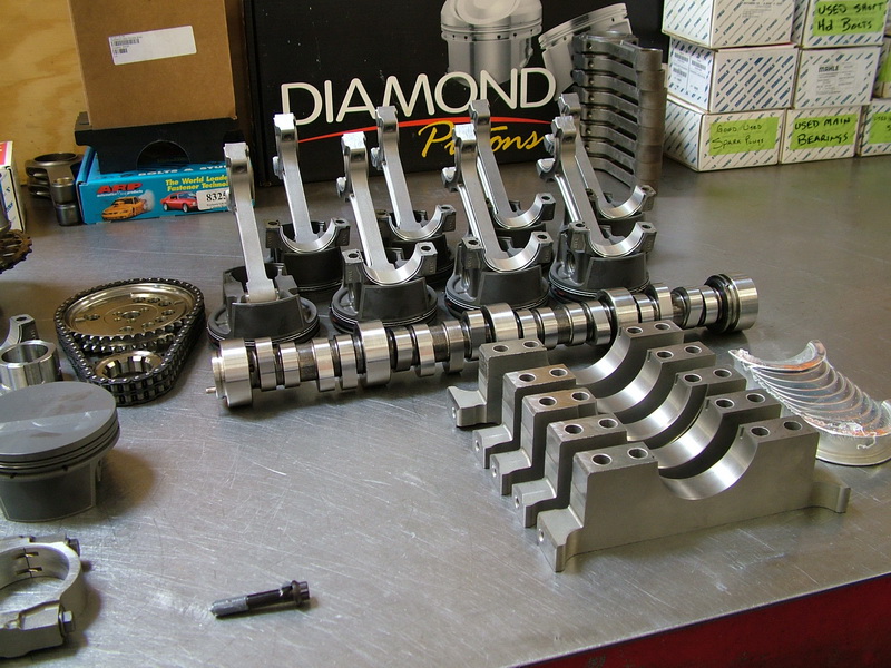
Crank, camshaft, pistons, rods, bearings and timing set ready for assembly. | ||||||||||||||||||||||||||||||||||||||||||||||||||||||||||||||||||||||||||||
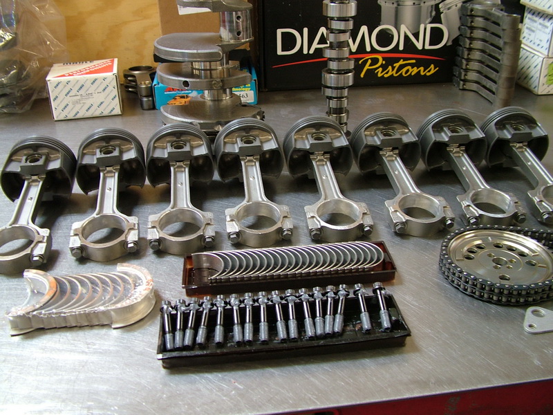 |
The crank is the stock cast nodular iron, internally balanced piece with with undercut and rolled fillet journals. Pistons are aftermarket Mahle brand forged aluminum. The camshaft is an aftermarket performance piece. |
||||||||||||||||||||||||||||||||||||||||||||||||||||||||||||||||||||||||||||
 |
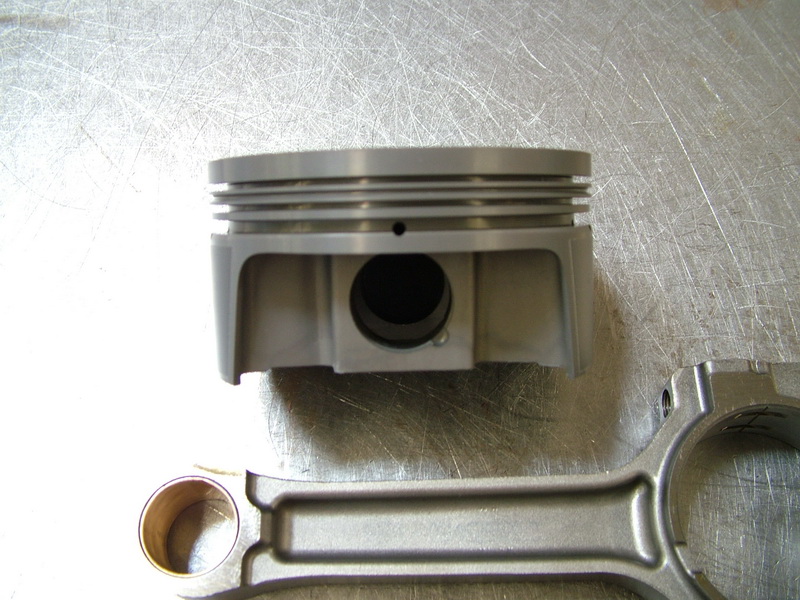
Rod and piston. Note the polymer antifriction-coated pistons and floating wrist pins. |
||||||||||||||||||||||||||||||||||||||||||||||||||||||||||||||||||||||||||||
 |
Internal engine goodness! | ||||||||||||||||||||||||||||||||||||||||||||||||||||||||||||||||||||||||||||
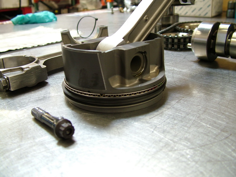 |
The LS2 piston ring package is a study in hi-tech engineering technology. Its ring grooves are machined with a slight upward tilt. The top ring is moly-faced steel and "coin twisted," which means its shape in side view is slightly conical. This design improves the ring's sealing when under combustion pressure as the top ring's tilt disappears as the ring land flexes under the pressure of combustion such that sealing and oil control are optimized. The tilt of the other two grooves enhances the ability of the second and the oil rings to scrape oil off the cylinder walls. The second ring is cast iron with a "Napier" cut face. The oil ring is a three-piece design, with two rails and an expander (the honeycomb looking piece at left). Apart from just sounding cool - all this technology allows the LS2 to use fairly low piston ring spring tension while maintaining good oil control, which reduces friction as the piston moves through the cylinder bore. This in turn reduces heat and power-robbing drag. |
||||||||||||||||||||||||||||||||||||||||||||||||||||||||||||||||||||||||||||
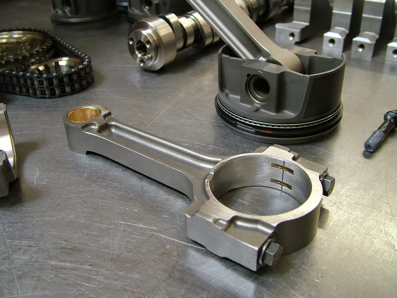 |
The connecting rod is a 6.1", sintered, forged, shot-peened and net-shape piece. The small ends are bushed for a floating pin (full-floating wrist pin), which enhances reliability/durability as well as reducing cold piston knock at startup. The bushings are silicon-bronze and have an oil-feed groove milled into them. To make the rods, steel powder is poured into a mold which is then heated and subjected to great pressure. This "sinters" the steel into the rod form. From there the rod goes through a conventional forging process and shot-peening. |
||||||||||||||||||||||||||||||||||||||||||||||||||||||||||||||||||||||||||||
 |
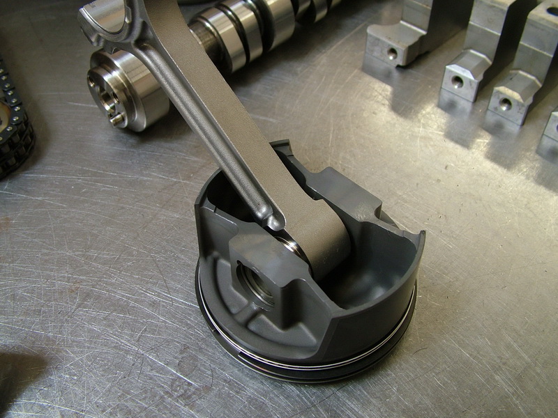
The underside of the piston. As the piston moves down in the bore, oil is scraped off the walls by the oil ring then is "flushed" down the oil holes and into the interior of the piston. |
||||||||||||||||||||||||||||||||||||||||||||||||||||||||||||||||||||||||||||
 |
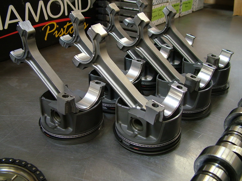
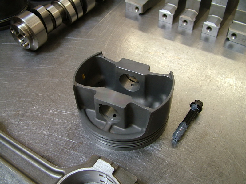
The forged Mahle pistons feature oil drainback notches drilled in the skirt, just below the oil-ring groove, going downwards into the piston's interior. These holes, two adjacent to the major thrust surface and two adjacent to the minor thrust surface, improve oil drainage from below the oil ring. |
||||||||||||||||||||||||||||||||||||||||||||||||||||||||||||||||||||||||||||
 |
Forged Mahle piston and rod. | ||||||||||||||||||||||||||||||||||||||||||||||||||||||||||||||||||||||||||||
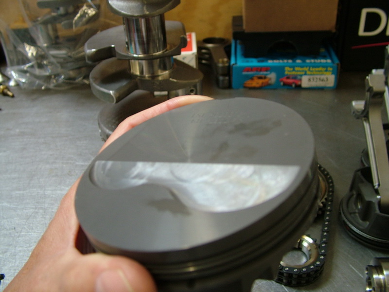 |
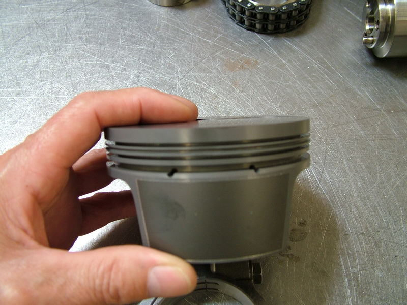
Top of the forged Mahle piston. | ||||||||||||||||||||||||||||||||||||||||||||||||||||||||||||||||||||||||||||
 |
The bottom-end components, ready for install. | ||||||||||||||||||||||||||||||||||||||||||||||||||||||||||||||||||||||||||||
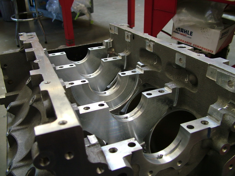 |
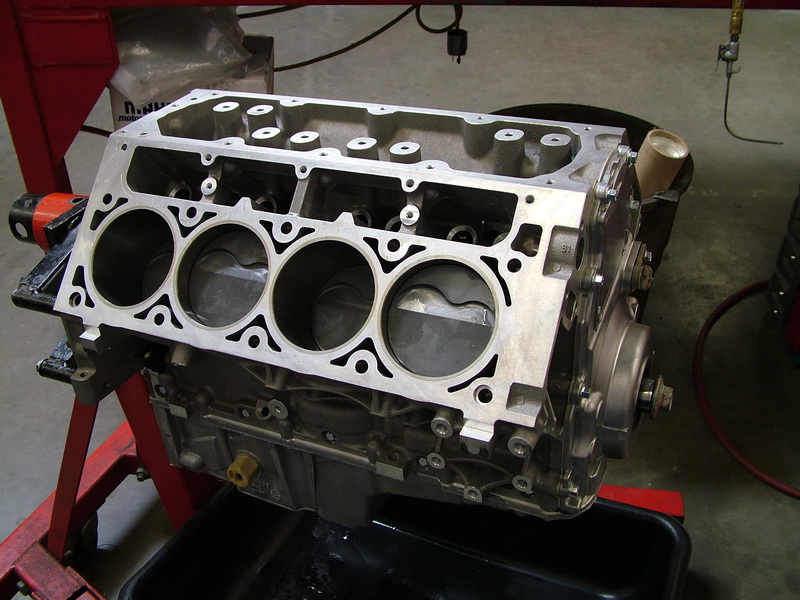
The 319-T5 aluminum alloy, deep-skirt LS2 block with cast-in-place iron cylinder bore liners and cross-bolted main caps is precision sand cast and strengthened with controlled cooling during the casting process. | ||||||||||||||||||||||||||||||||||||||||||||||||||||||||||||||||||||||||||||
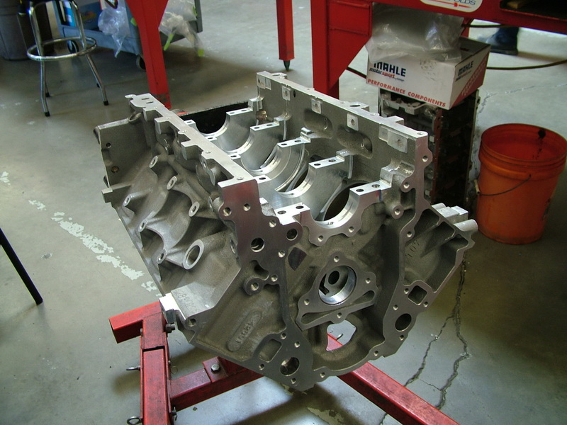 |
Compared to an old-school small-block Chevy, the Gen IV LS2 cylinders have a slightly smaller bore and longer stroke, which creates more area between the cylinders for rigidity, durability and cooling. The LS2 engine block is designed to be very rigid, based on its overall shape, to help reduce the effects of combustion heat and energy which can bend and distort an engine block and generate noise and vibration. Typically, an engine block ends at the centreline of the crankshaft. The LS2 has a “deep skirt” that extends down past the main bearing caps. Two 8mm bolts tie each main bearing cap directly into the engine block horizontally, and four 10mm bolts are oriented vertically. The result is 6-bolt, cross-bolted, main bearing caps for durability as well as low noise and vibration. |
||||||||||||||||||||||||||||||||||||||||||||||||||||||||||||||||||||||||||||
LS2 blocks have cast-in ports in the main webs (in the block between the cylinder bores) for crankcase bay-to-bay breathing. These windows or ports are very important for allowing the oil vapour to move around in the bottom end at high RPM without creating excessive back-pressure against the pistons during their down-travel stroke. Of note, the LS2 block is some 15.4 lbs lighter than an LS1 block. |
|||||||||||||||||||||||||||||||||||||||||||||||||||||||||||||||||||||||||||||
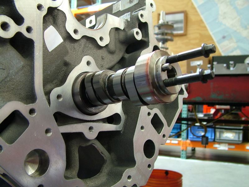 |
In goes the camshaft. The Turn Key "510" LS2 uses a cam with the following specs: Valve Lift: 0.562" - intake / 0.554" exhaust |
||||||||||||||||||||||||||||||||||||||||||||||||||||||||||||||||||||||||||||
Valve lift is how far the cam lobe will open the valve at its peak. Valve lift = cam lobe lift (the physical measurement of the lift of the actual cam lobe) x rocker arm ratio (e.g. 0.329" lobe lift x 1.7:1 rocker ratio = 0.562" valve lift). Duration is a measurement of how long the valve is open, expressed in crankshaft degrees. The measurement is made from the point at which the opening valve is 0.050" from the valve seat, until it returns to 0.050" above the valve seat - hence the "@ .050" you always see in the spec. Lobe separation angle (LSA) (sometimes referred to as Lobe Centre Angle) is the distance, in crank degrees, of the centres (point of peak lift) of the intake and exhaust lobes. What this tells you is how far apart, in crankshaft rotation degrees, the two lobes are spread. Or in other words, the amount of valve overlap a cam provides, which is the amount of time between the exhaust stroke and the intake stroke that both valves are open at the same time. To those used to bench-racing performance camshafts, those specs may not seem terribly aggressive - and there's a very good reason for that. We all know that an engine works like a giant air pump - more air in and more air out = more power. In the days of old, with traditional small-block engines, the way to make real power was with aggressive cam timing because the technology of the day made it difficult to otherwise get the required air flow at the top end. Today, things are different. GM put an awful lot of time, design, and dollars into engineering the Gen IV V8 motors with huge flow - from the intake to the heads. Turn Key take this base and add a performance cam, but with fairly conservative cam timing. This fattens up the torque curve and gives you tremendous low and mid-range without losing the top-end (which was the old-school characteristic trade-off) because you have huge air flow. With this design, you get all the responsiveness down low and still have all the top end, but without the sudden, flip-the-switch, "coming on the cam" feeling. The bottom-line result is a very high performance engine that performs across the entire rpm range. Some old-school folks may struggle with this concept because of the erroneous belief that "comin' on the cam" is demonstrative of a powerful engine. The truth is, modern engineering techniques ( particularly computerized flow modelling), combined with expert aftermarket building and tuning techniques mean you can finally have a high-performance motor with a torque curve that's flatter than Saskatchewan but that also makes huge top-end power, isn't "peaky", idles well, and has great throttle response across the band. For any vehicle this means a motor that is both easy and fun to drive - but in an off-road rig it is a perfect match because of the demands of off-road performance - sometimes you need low-speed torque, sometimes you need high-end horsepower. |
|||||||||||||||||||||||||||||||||||||||||||||||||||||||||||||||||||||||||||||
 |
Camshaft in and crank being installed. Front view. |
||||||||||||||||||||||||||||||||||||||||||||||||||||||||||||||||||||||||||||
 |
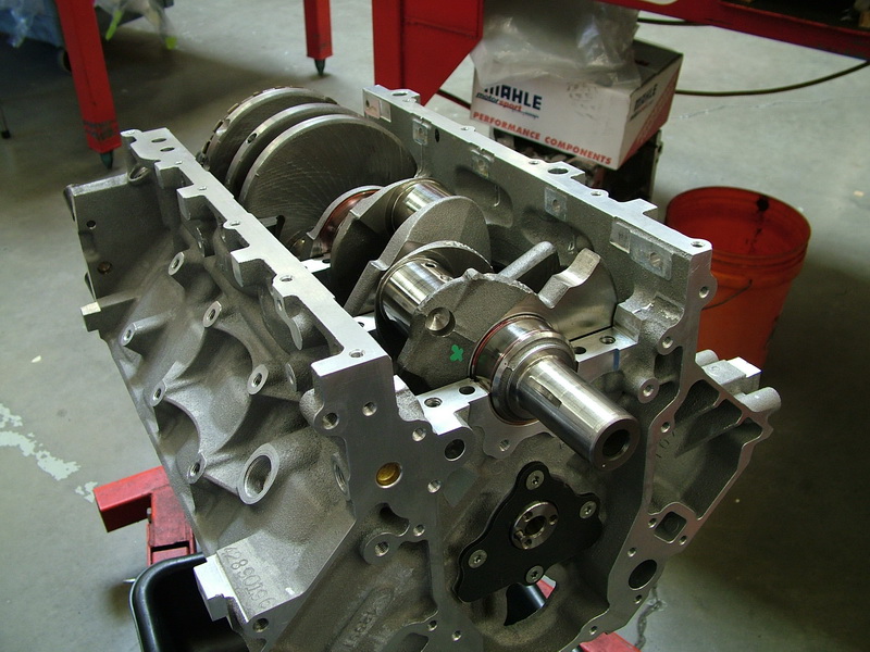
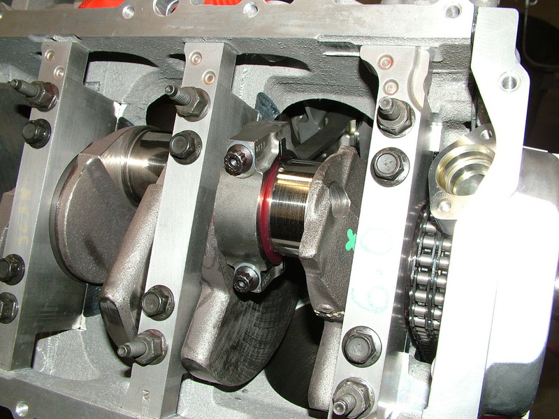
Crank installed - rear view. Note the 58X crankshaft position encoder at the rear of the crank that provides fast, accurate information on the crankshaft’s position during rotation. |
||||||||||||||||||||||||||||||||||||||||||||||||||||||||||||||||||||||||||||
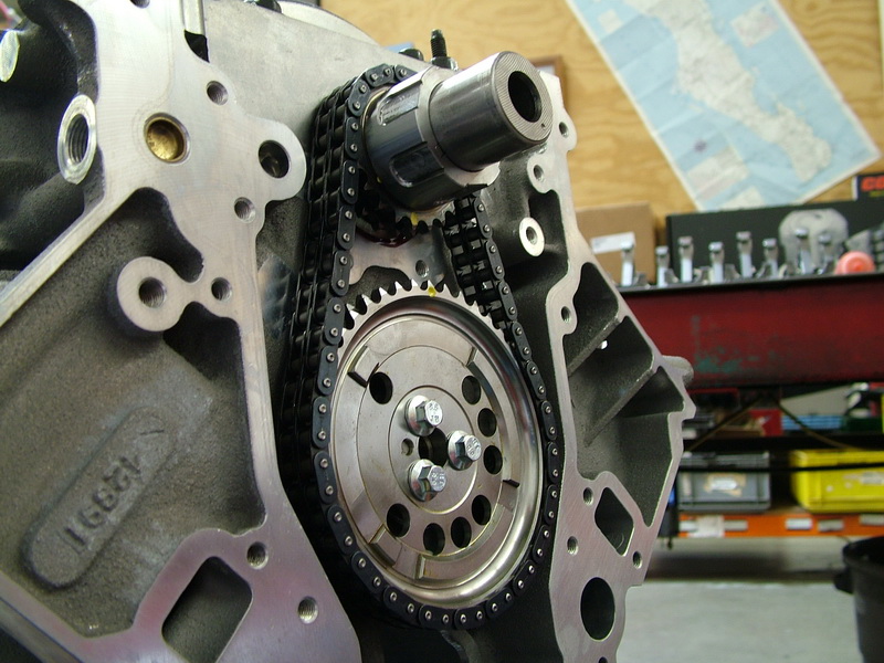 |
Double roller timing chain being installed. |
||||||||||||||||||||||||||||||||||||||||||||||||||||||||||||||||||||||||||||
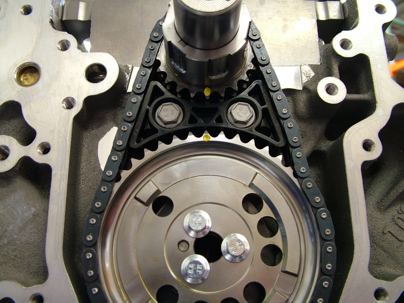 |
Timing chain damper installed. The damper maintains optimal chain tension for the life of the engine and eliminates any flapping motion that might develop as the chain stretches with mileage. | ||||||||||||||||||||||||||||||||||||||||||||||||||||||||||||||||||||||||||||
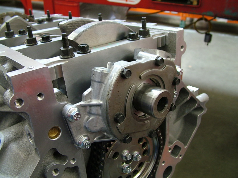 |
High-efficiency Gerotor oil pump, driven off the front of the crankshaft. This high-flow oil pump provides approximately 30% more volume than the stock LS2 oil pump. |
||||||||||||||||||||||||||||||||||||||||||||||||||||||||||||||||||||||||||||
 |
Piston being installed. | ||||||||||||||||||||||||||||||||||||||||||||||||||||||||||||||||||||||||||||
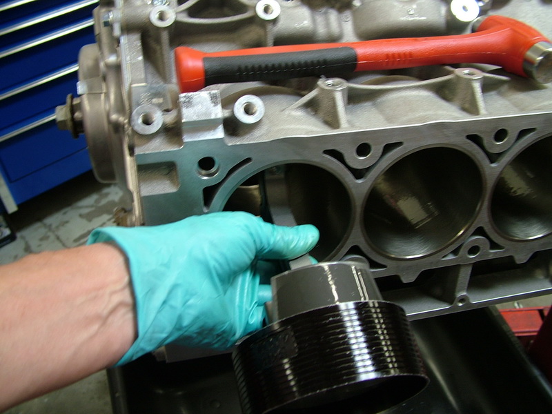 |
Piston being installed. Note the block has siamesed bores. This means there are no water passages between the cylinder bores. A lot of development went into the design of the Gen IV water jacket to get good heat rejection without the need for water between the bores. |
||||||||||||||||||||||||||||||||||||||||||||||||||||||||||||||||||||||||||||
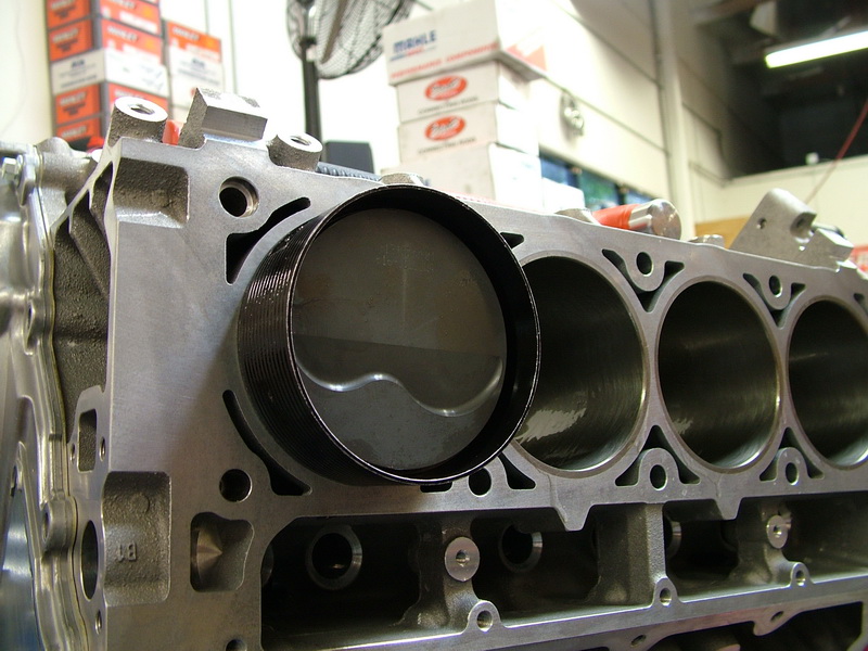 |
Piston being installed. | ||||||||||||||||||||||||||||||||||||||||||||||||||||||||||||||||||||||||||||
 |
Main bearing caps being installed. | ||||||||||||||||||||||||||||||||||||||||||||||||||||||||||||||||||||||||||||
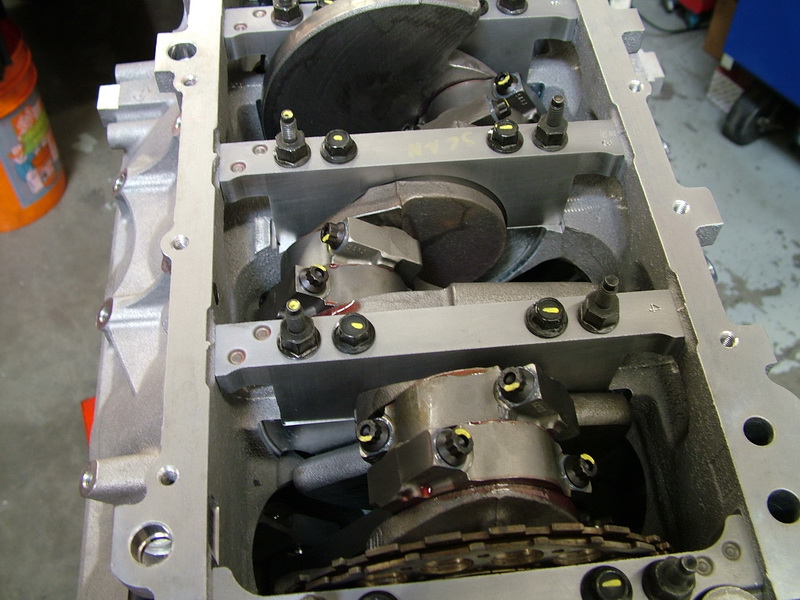 |
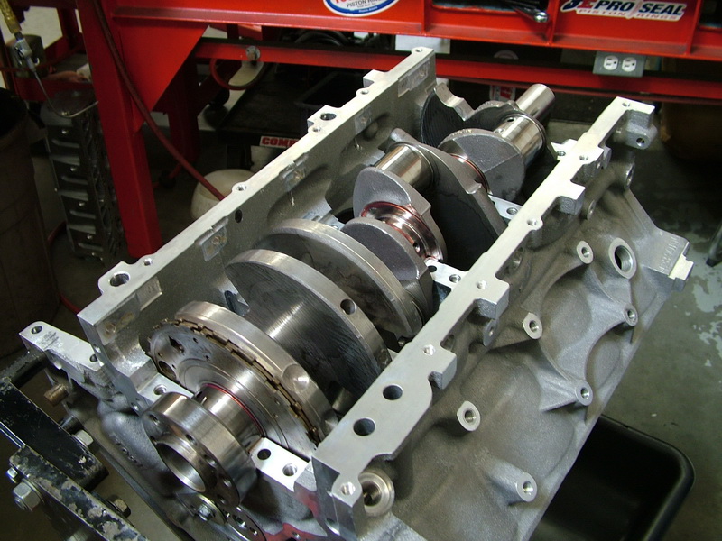
Bottom-end complete. In this shot you can clearly see the cast-in ports in the main webs between the cylinder bores for crankcase bay-to-bay breathing. |
||||||||||||||||||||||||||||||||||||||||||||||||||||||||||||||||||||||||||||
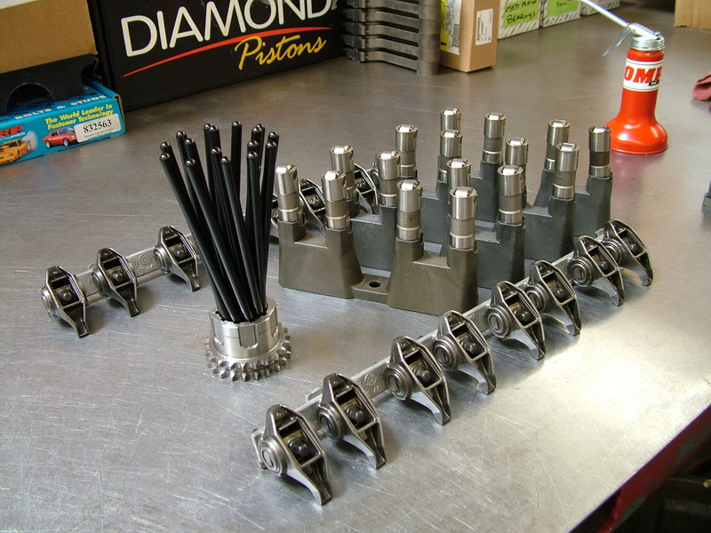 |
Valvetrain components assembled and ready for installation. In the LS2 valvetrain:
|
||||||||||||||||||||||||||||||||||||||||||||||||||||||||||||||||||||||||||||
 |
"Short block" complete with F-body oil pan ready for valvetrain and heads. | ||||||||||||||||||||||||||||||||||||||||||||||||||||||||||||||||||||||||||||
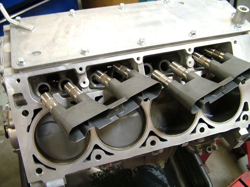 |
Hydraulic roller lifters being installed. | ||||||||||||||||||||||||||||||||||||||||||||||||||||||||||||||||||||||||||||
 |
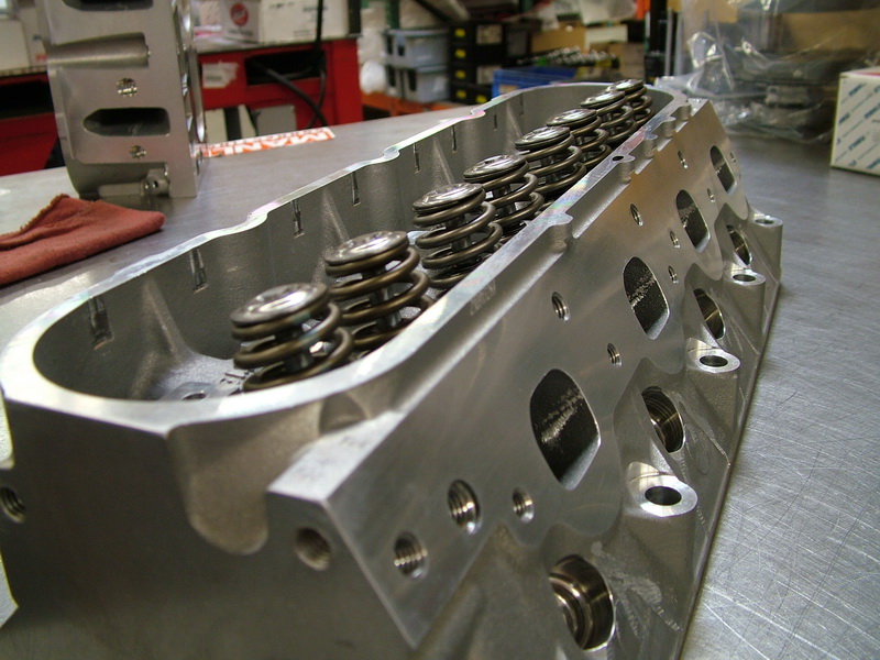
Underside of LS2 cylinder head showing combustion chamber. The LS2 uses a four-bolt cylinder head design rather than the five-bolt design used in previous Gen I and II small blocks. This four-bolt design virtually eliminates bore distortion. Head bolts are threaded deeply into the block, resulting in improved clamping and better sealing. |
||||||||||||||||||||||||||||||||||||||||||||||||||||||||||||||||||||||||||||
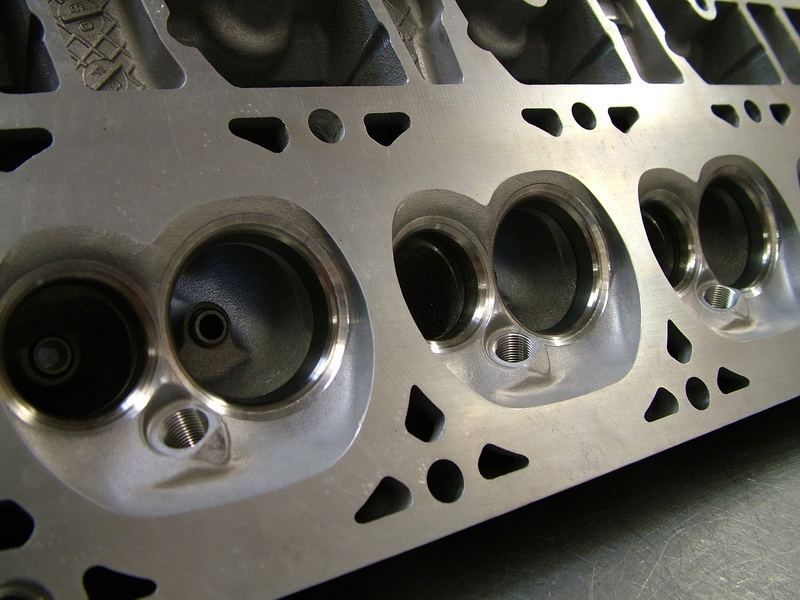 |
The LS2 heads incorporate flow characteristics developed in the Corvette C5R racing program. Valve seats have a 60-46-30-degree multi-angle finishing and the valve faces are finished at 45°. |
||||||||||||||||||||||||||||||||||||||||||||||||||||||||||||||||||||||||||||
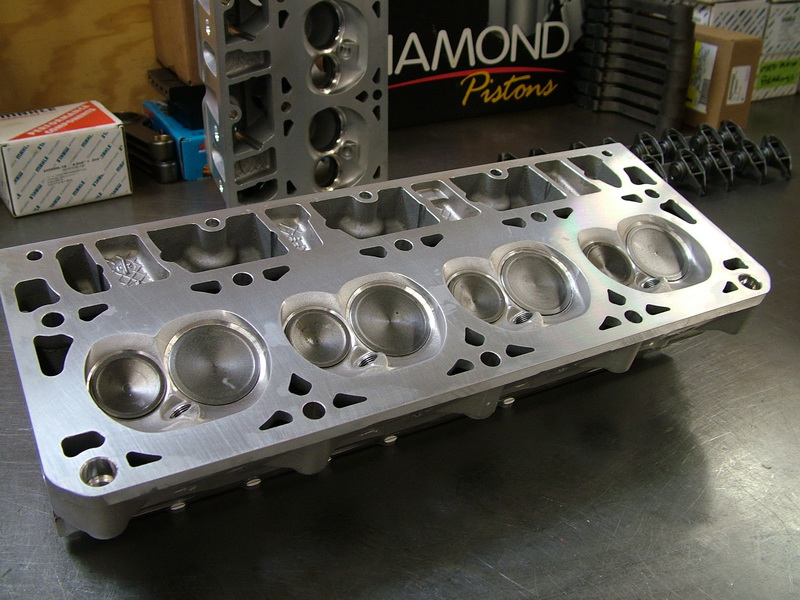 |
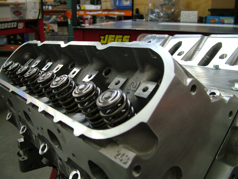
2.00” stainless steel intake valves and 1.55” stainless steel exhaust valves installed in the cylinder head. |
||||||||||||||||||||||||||||||||||||||||||||||||||||||||||||||||||||||||||||
 |
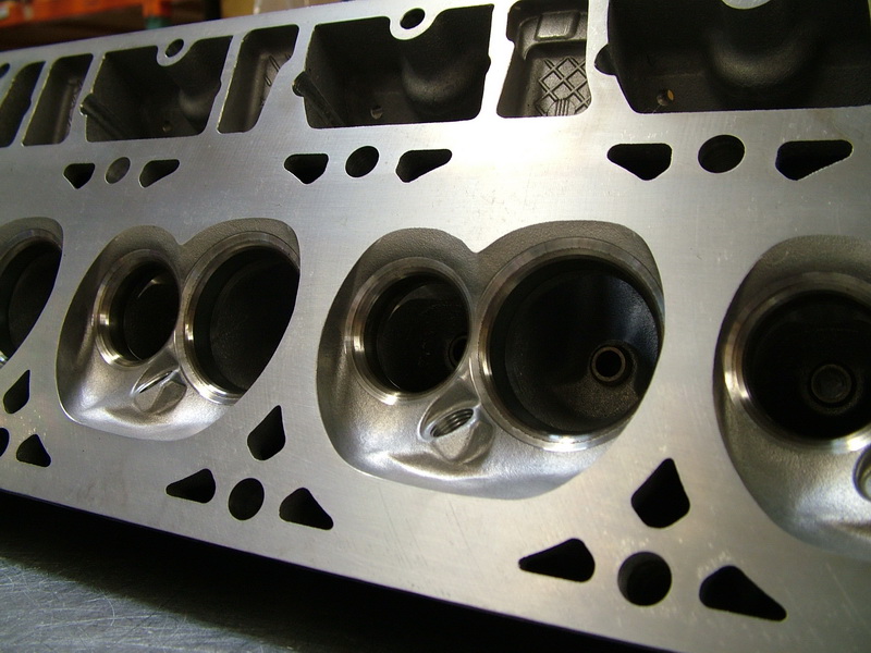
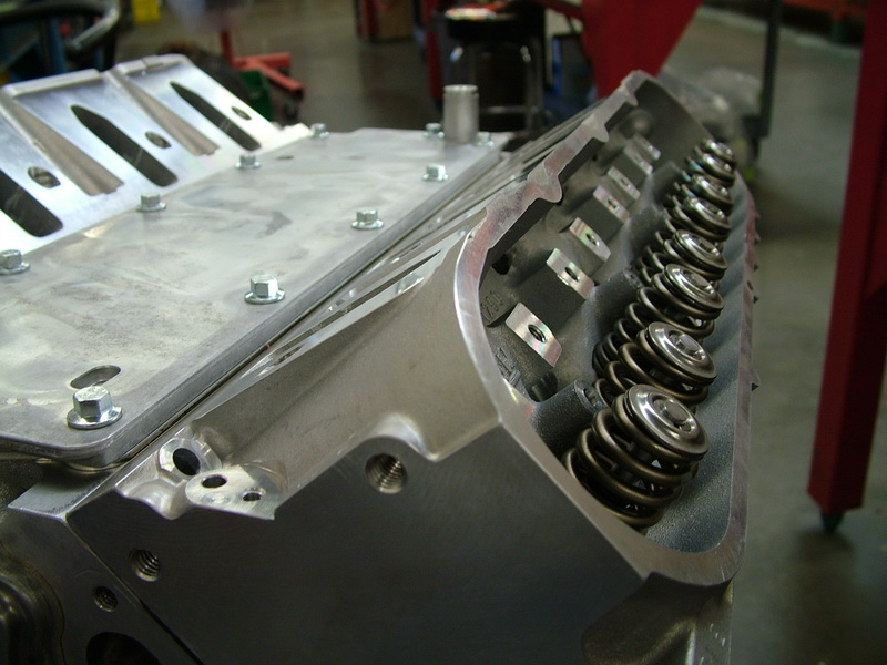
LS2 cylinder head showing "cathedral" style intake ports. The LS2 cylinder heads use “replicated ports” to optimize airflow into the engine. Replicated ports are identical in every detail, allowing for consistent cylinder-to-cylinder airflow distribution. The incoming air also has a “straight shot” into the combustion chamber. |
||||||||||||||||||||||||||||||||||||||||||||||||||||||||||||||||||||||||||||
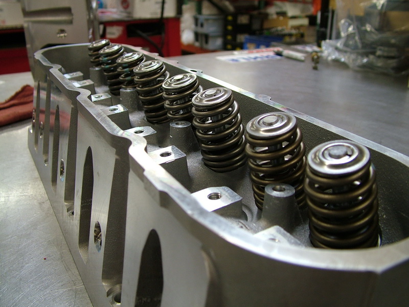 |
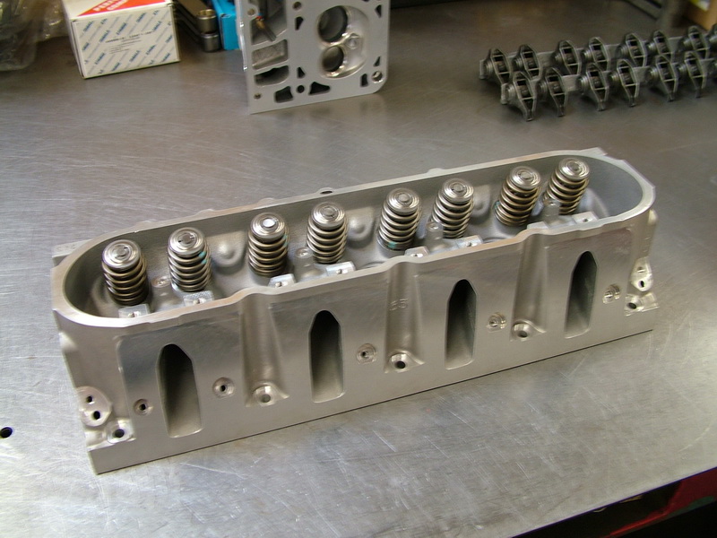
To match the performance camshaft and keep the valvetrain under control, Turn Key install Heavy-Duty beehive oval-wire chromium-silicate valvesprings. The beehive shape eliminates the need for a damper spring inside the main spring, and the oval wire helps to improve high-rpm valve control. | ||||||||||||||||||||||||||||||||||||||||||||||||||||||||||||||||||||||||||||
 |
LS2 cylinder head showing replicated D-shaped exhaust ports. | ||||||||||||||||||||||||||||||||||||||||||||||||||||||||||||||||||||||||||||
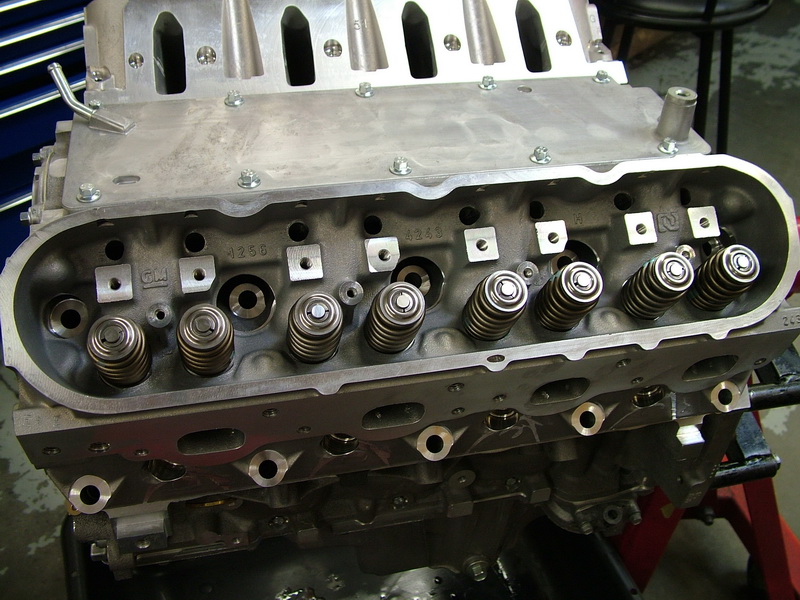 |
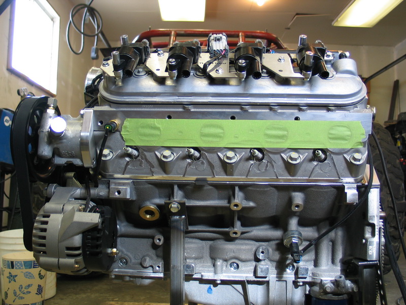
Cylinder heads installed on block. Note huge cathedral-shaped intake ports. |
||||||||||||||||||||||||||||||||||||||||||||||||||||||||||||||||||||||||||||
 |
Cylinder head and valley cover installed. | ||||||||||||||||||||||||||||||||||||||||||||||||||||||||||||||||||||||||||||
 |
Head ready for pushrods and rocker arms. | ||||||||||||||||||||||||||||||||||||||||||||||||||||||||||||||||||||||||||||
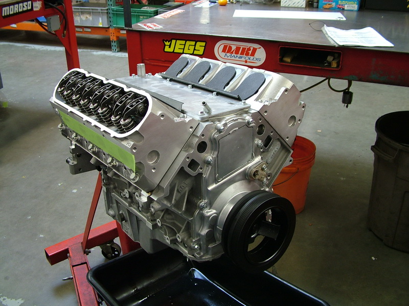 |
Complete "long block" assembly with front cover and crank pulley installed. Ready for intake manifold, fuel injection, and front accessories. |
||||||||||||||||||||||||||||||||||||||||||||||||||||||||||||||||||||||||||||
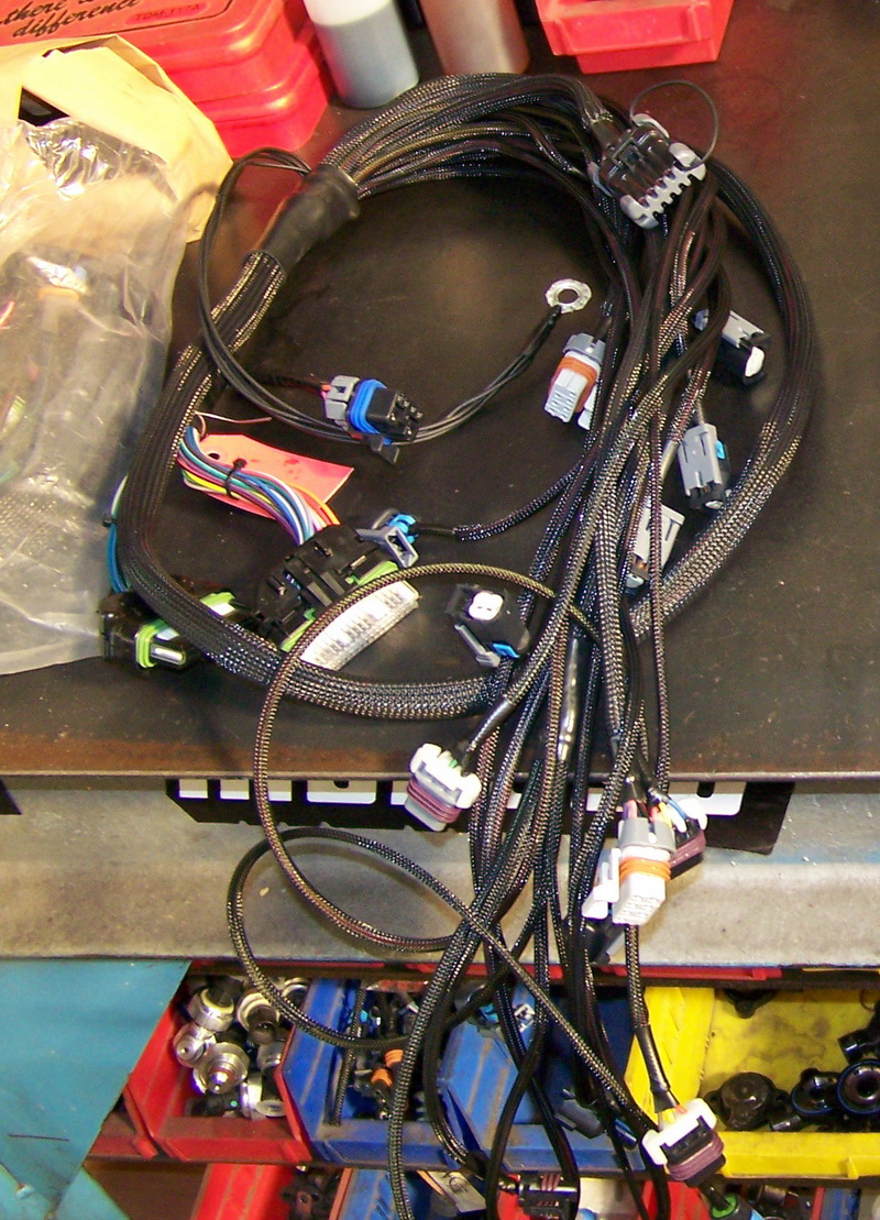 |
Turn Key custom marine-grade engine wiring harness. The harness uses all OEM "Weatherpak" style connectors | ||||||||||||||||||||||||||||||||||||||||||||||||||||||||||||||||||||||||||||
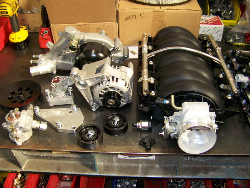 |
Intake and front accessories ready to be installed. The composite thermoplastic intake manifold is strong, yet lighter than aluminum, smoother, and runs cooler, allowing high-density intake air to flow with less restriction through the manifold. This design allows for perfectly equal-length-and-volume intake runners and smoother runner walls than possible with previous cast steel and aluminum styles. |
||||||||||||||||||||||||||||||||||||||||||||||||||||||||||||||||||||||||||||
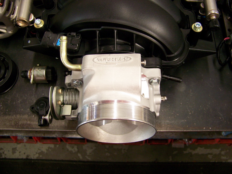 |
Custom Turn key 90mm cable-operated throttle body. | ||||||||||||||||||||||||||||||||||||||||||||||||||||||||||||||||||||||||||||
 |
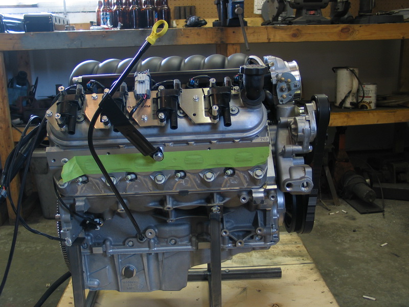
Intake manifold, throttle body, and rocker covers installed. Note stock stainless steel fuel rail. |
||||||||||||||||||||||||||||||||||||||||||||||||||||||||||||||||||||||||||||
 |
Stock fuel rail replaced with billet aluminum rail. Sensors and wiring being added. |
||||||||||||||||||||||||||||||||||||||||||||||||||||||||||||||||||||||||||||
 |
Individual coil packs mounted on rocker covers. | ||||||||||||||||||||||||||||||||||||||||||||||||||||||||||||||||||||||||||||
 |
F-body (2002 Camaro) water pump installed. | ||||||||||||||||||||||||||||||||||||||||||||||||||||||||||||||||||||||||||||
 |
Power steering pump (Howe 1450 PSI TC), alternator (02 Camaro 120 amp), and idlers added. | ||||||||||||||||||||||||||||||||||||||||||||||||||||||||||||||||||||||||||||
 |
Wiring completed (note ECM resting on right rocker cover by oil fill port) "Test" serpentine belt installed. This is a special shorter belt that doesn't turn the PS pump so the pump need not be filled for the engine's test run-up. |
||||||||||||||||||||||||||||||||||||||||||||||||||||||||||||||||||||||||||||
 |
Rear of engine before rear cover installed. | ||||||||||||||||||||||||||||||||||||||||||||||||||||||||||||||||||||||||||||
 |
Rear cover installed. | ||||||||||||||||||||||||||||||||||||||||||||||||||||||||||||||||||||||||||||
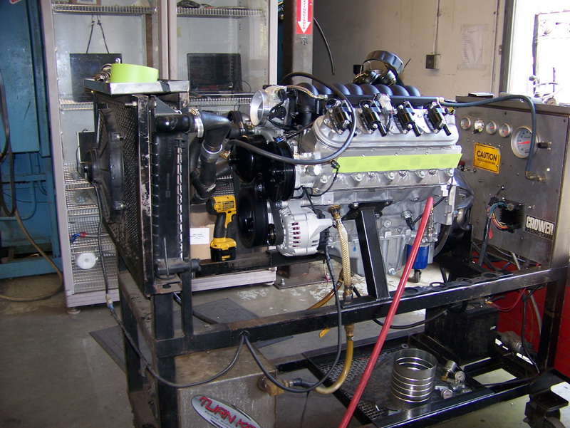 |
Motor installed on dyno for pre-shipping run up. | ||||||||||||||||||||||||||||||||||||||||||||||||||||||||||||||||||||||||||||
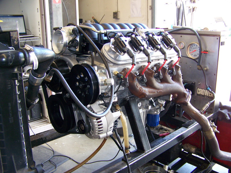 |
Plug wires and temporary exhaust manifolds installed for pre-shipping run up. Each motor is run up and thoroughly checked before shipping. |
||||||||||||||||||||||||||||||||||||||||||||||||||||||||||||||||||||||||||||
 |
Coil covers installed and motor crated for shipping. | ||||||||||||||||||||||||||||||||||||||||||||||||||||||||||||||||||||||||||||
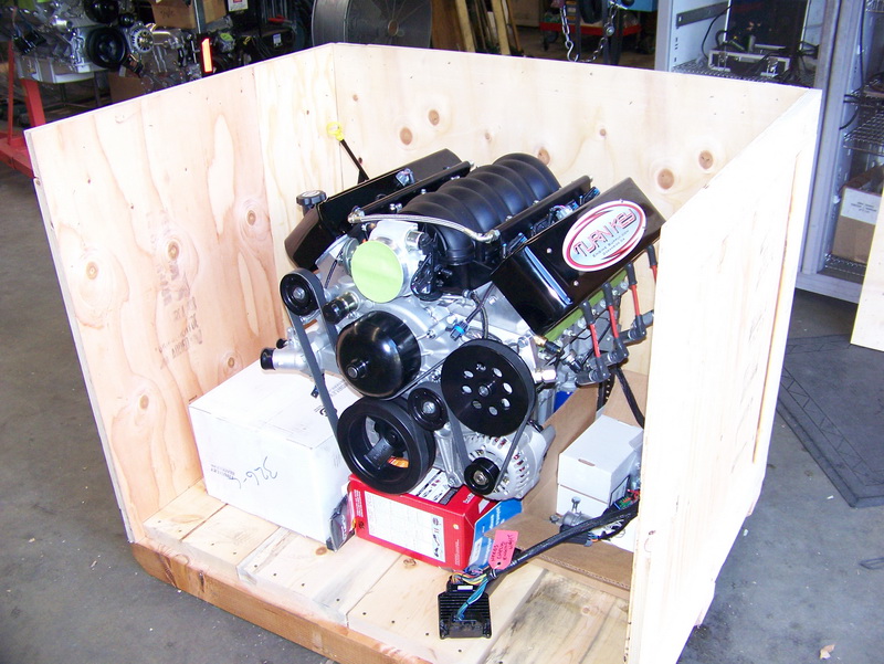 |
And this is how it looked, complete with all the accessories and parts required, ready to be buttoned up and shipped. | ||||||||||||||||||||||||||||||||||||||||||||||||||||||||||||||||||||||||||||
Here is a cool animated video clip showing an LS2 being built:
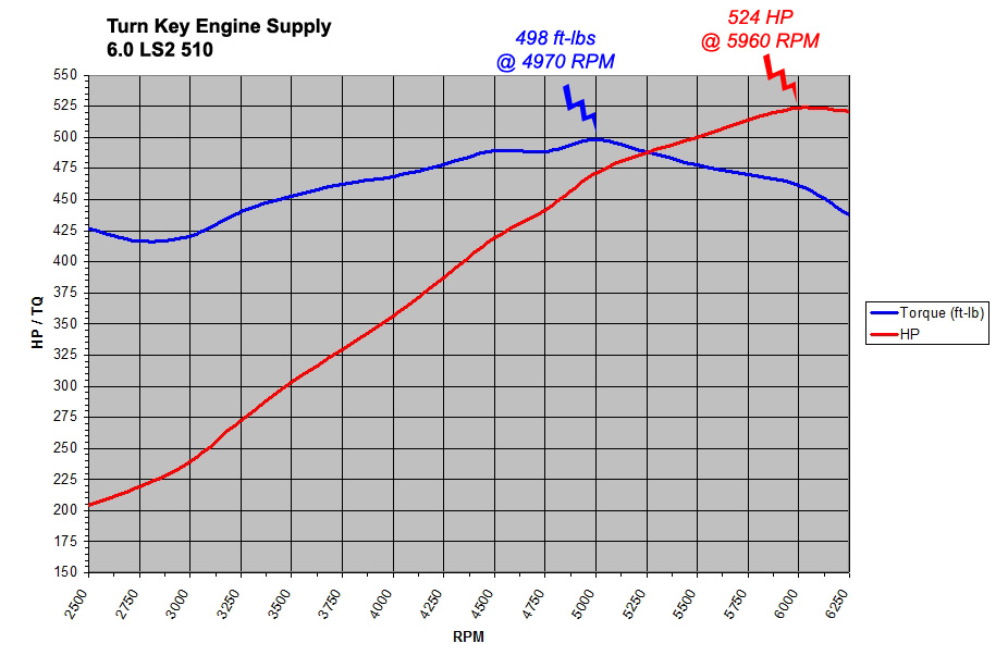
If the above imbedded Youtube video doesn't work or play for you, you can also download the video by clicking on one of these links: LS2 Build Animation - MP4 format (9.8 Mb) LS2 Build Animation - FLV format (7.4 Mb) Finally, and perhaps most import in any engine build - what are the results? Here is the Dyno Curve for my motor:
Note that differences between the "rated" output of the motor and the actual dyno results are due to factors such as air filter, exhaust, dyno calibration and operation, and even atmospheric conditions at the time of test. Part 4 - External Features and ComponentsOK, fast forward back to where we left off before we had a look at the engine build, and the motor is delivered and out of the crate. Time to have a good look at all the little features and components of the Turn Key "510" LS2: Oil System The LS2 uses a high-efficiency Gerotor oil pump, driven off the front of the crankshaft. Because I will be running an oil cooler as well as a remote-mounted oil filter, Turn Key built my LS2 with a high-volume oil pump that provides about 30% more volume than the stock LS2 pump. The Gen III/IV oiling system goes like this: Oil pan – pickup tube – crank driven gerotor pump – main oil galley (driver’s side of block) – oil filter – up rear driver’s side of block – main feed galley (runs through the lifter bodies) – up to top of engine through pushrod passages – drains back to pan through drain-back passages throughout the heads and block – return to oil pan. Ignition System Fuel Injection Cooling |
|||||||||||||||||||||||||||||||||||||||||||||||||||||||||||||||||||||||||||||
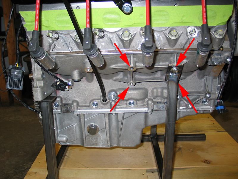 |
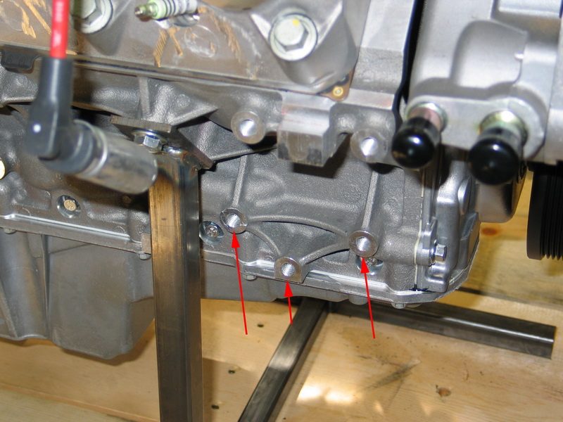
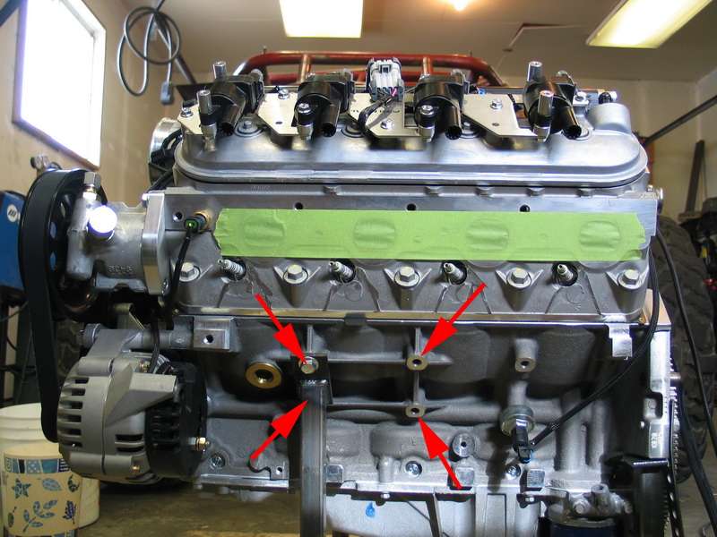
Motor mount bosses, right side of block. The red arrows indicate the bosses on the block for the LS2 motor mounts. The bolt pattern is a rectangle 4-13/32" wide and 3-1/8" tall. The motor mount bolts are 10mm. |
||||||||||||||||||||||||||||||||||||||||||||||||||||||||||||||||||||||||||||
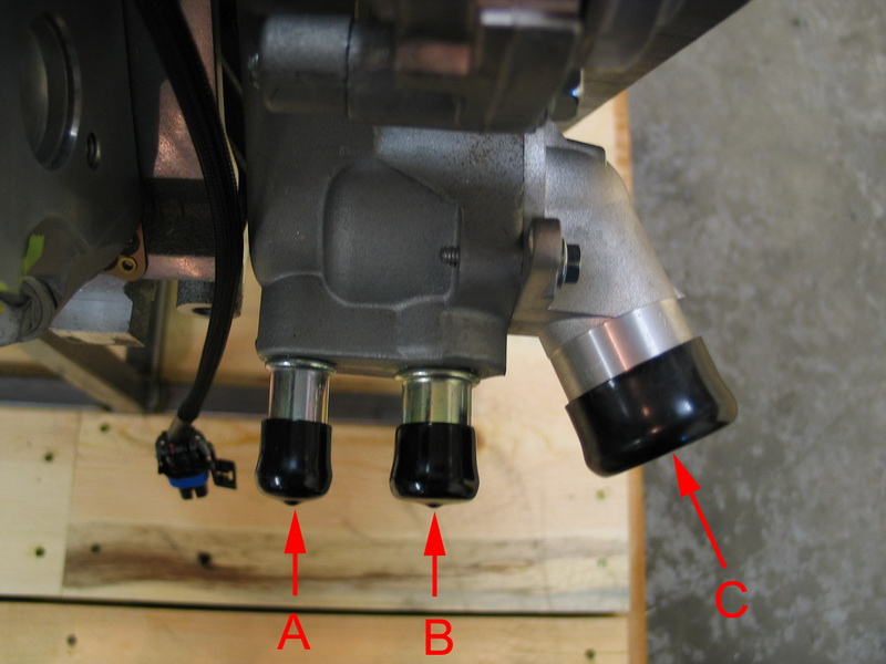 |
A = Water pump outlet to heater core, 5/8". B = Water pump inlet from heater core, 3/4". C = Water pump inlet / thermostat housing (in to engine from radiator), 1-9/16". |
||||||||||||||||||||||||||||||||||||||||||||||||||||||||||||||||||||||||||||
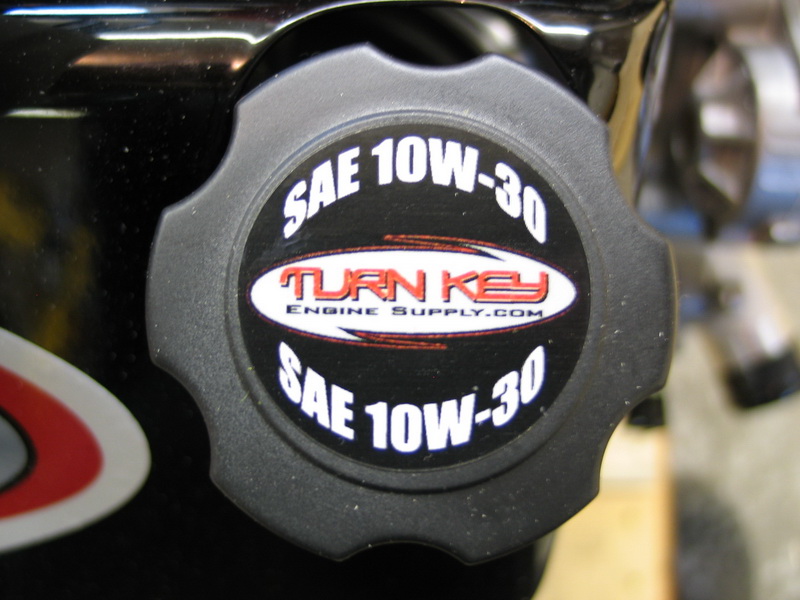 |
Oil filler cap. | ||||||||||||||||||||||||||||||||||||||||||||||||||||||||||||||||||||||||||||
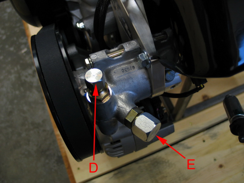 |
D = Power steering pump outlet (high pressure), AN-06. E = Power steering pump inlet (supply from reservoir), AN-10. |
||||||||||||||||||||||||||||||||||||||||||||||||||||||||||||||||||||||||||||
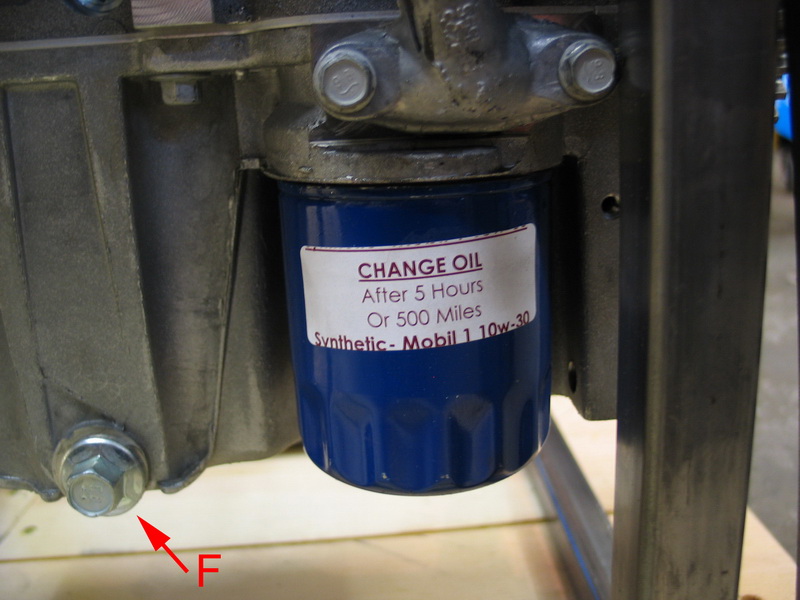 |
F = Oil pan drain plug. | ||||||||||||||||||||||||||||||||||||||||||||||||||||||||||||||||||||||||||||
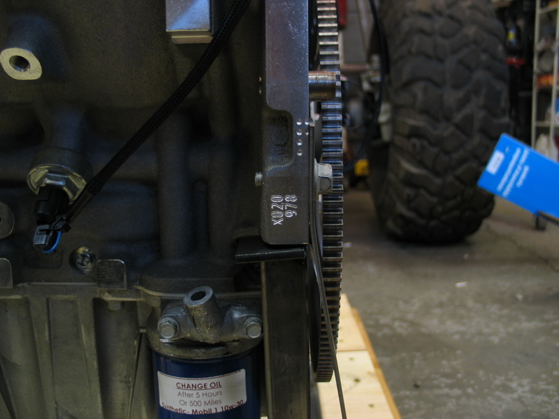 |
Stamped number on left rear of block: X020 978. | ||||||||||||||||||||||||||||||||||||||||||||||||||||||||||||||||||||||||||||
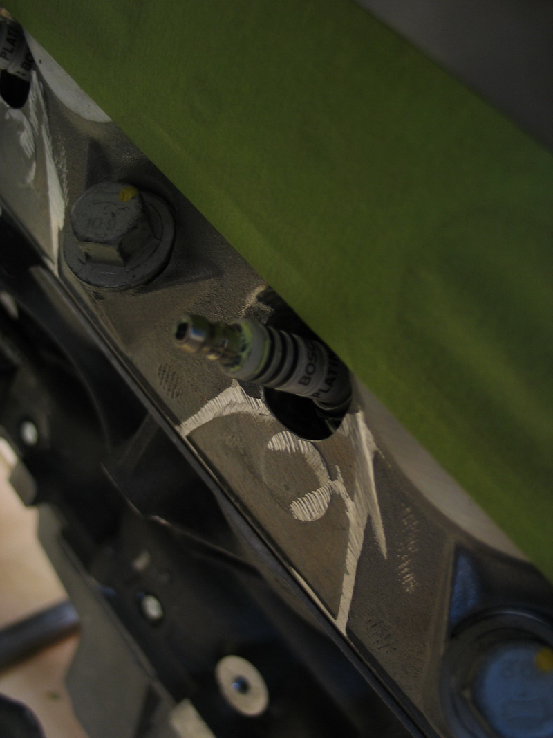 |
Bosch Platinum spark plugs, included in package and pre-installed. | ||||||||||||||||||||||||||||||||||||||||||||||||||||||||||||||||||||||||||||
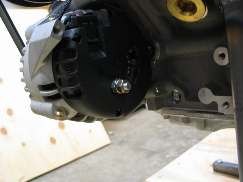 |
120 amp Delco alternator. The alternator is a 2-wire design - one wire for battery charging and voltage sensing, and one wire for the alternator excite (turn-on signal). If you are running an alternator dash light Turn Key will provide instructions on how to hook that up in series with the excite wire. |
||||||||||||||||||||||||||||||||||||||||||||||||||||||||||||||||||||||||||||
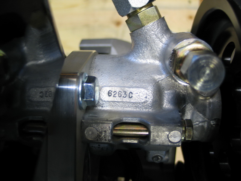 |
Howe 1450psi TC-style power steering pump. Stamped number: 6263C. | ||||||||||||||||||||||||||||||||||||||||||||||||||||||||||||||||||||||||||||
 |
6.0L head gasket. | ||||||||||||||||||||||||||||||||||||||||||||||||||||||||||||||||||||||||||||
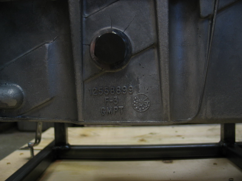 |
Plug installed in stock low-oil-level sensor location. Cast aluminum Camaro oil pan part number: 12558899. |
||||||||||||||||||||||||||||||||||||||||||||||||||||||||||||||||||||||||||||
 |
Stamped or engraved number on right front of block (just above stock air-conditioning compressor mount location): X20978. | ||||||||||||||||||||||||||||||||||||||||||||||||||||||||||||||||||||||||||||
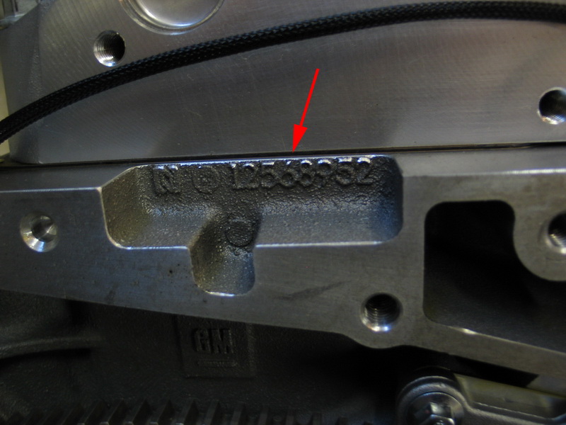 |
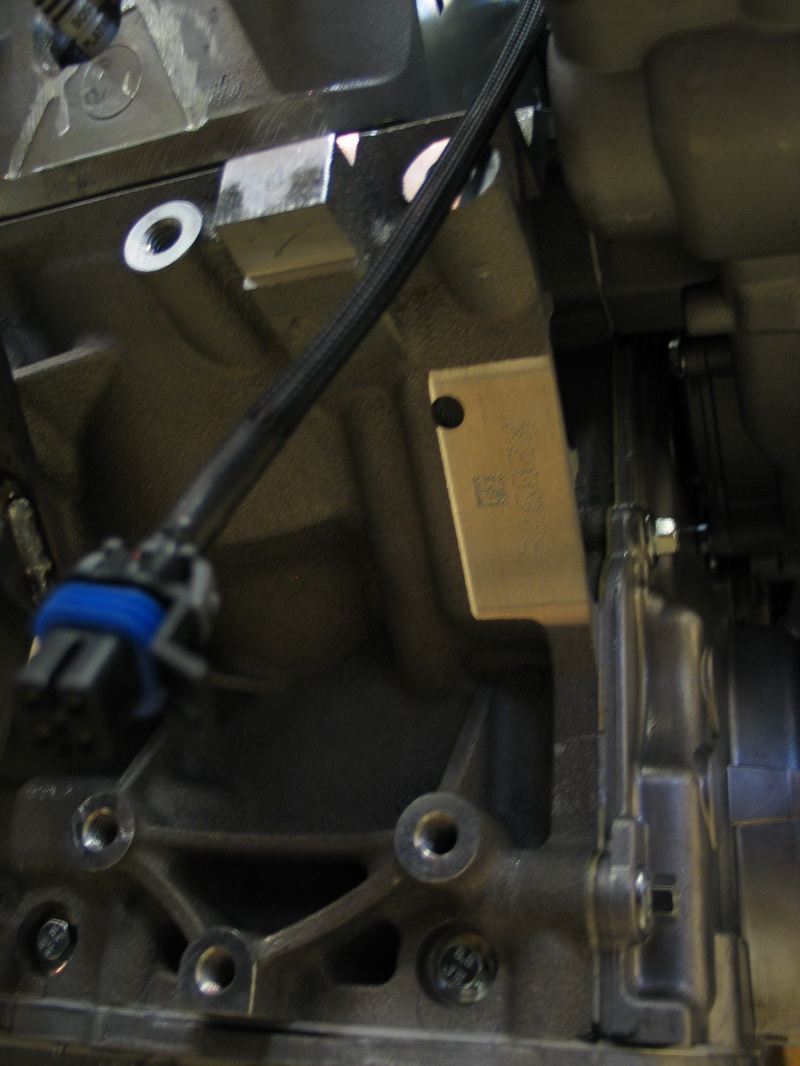
Cast-in number on top left rear of block, just below the head: 12568952. | ||||||||||||||||||||||||||||||||||||||||||||||||||||||||||||||||||||||||||||
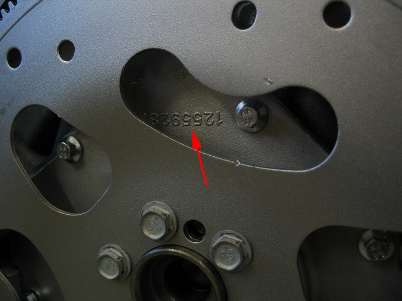 |
Cast-in number on engine rear cover, behind flexplate: 12559287. | ||||||||||||||||||||||||||||||||||||||||||||||||||||||||||||||||||||||||||||
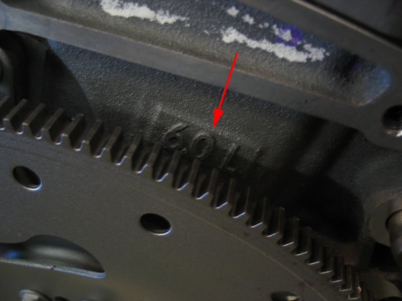 |
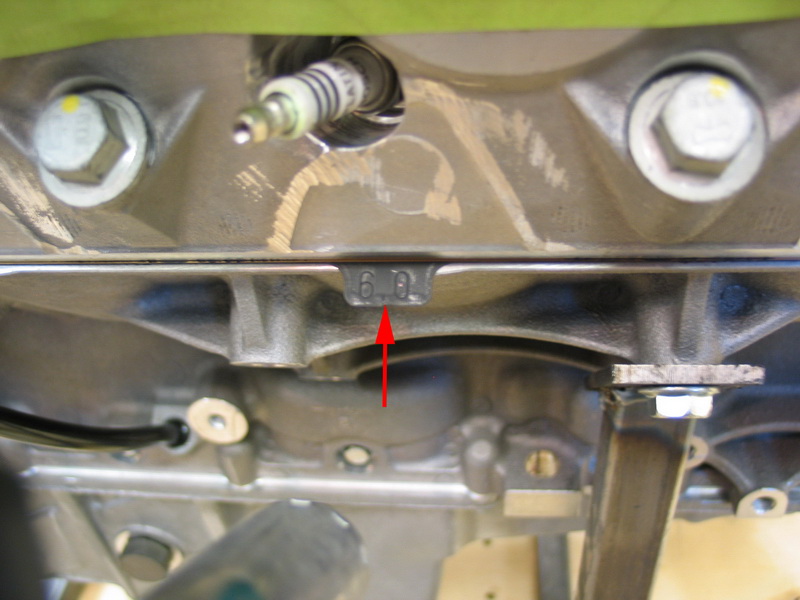
6.0L identification cast into block on right side, just behind the flexplate. | ||||||||||||||||||||||||||||||||||||||||||||||||||||||||||||||||||||||||||||
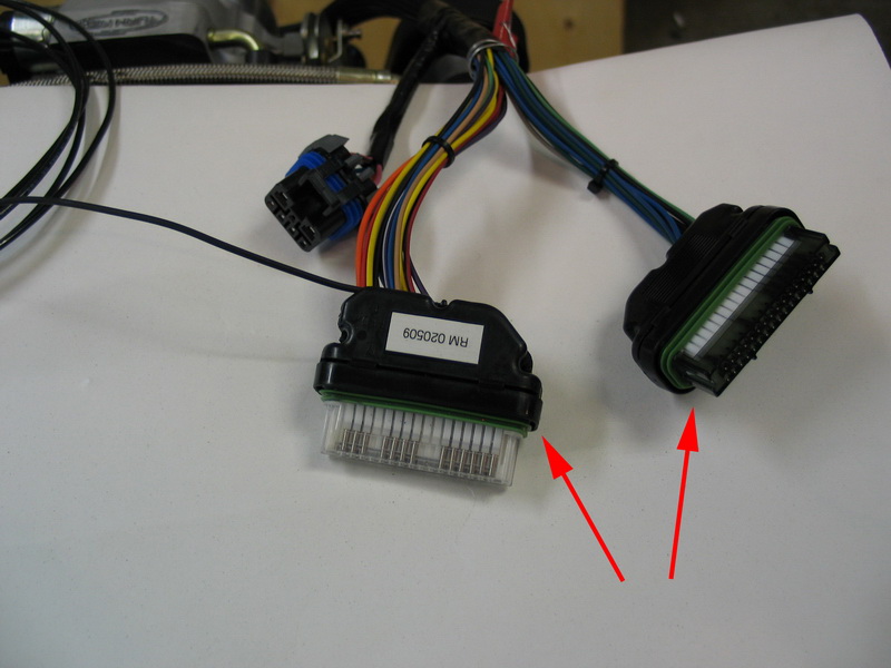 |
Main wiring harness connectors - these two connectors plug into the ECM. | ||||||||||||||||||||||||||||||||||||||||||||||||||||||||||||||||||||||||||||
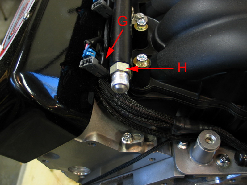 |
G = Fuel injector and connector. Fuel injectors are rated at 32.5 lb/hr at 58 psi. H = -06 AN fuel rail fitting. |
||||||||||||||||||||||||||||||||||||||||||||||||||||||||||||||||||||||||||||
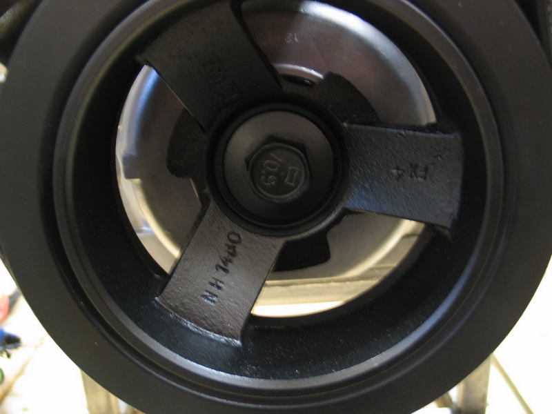 |
Crank Pulley. The bolt is marked "6.0". The spoke is stamped with: NH1480. | ||||||||||||||||||||||||||||||||||||||||||||||||||||||||||||||||||||||||||||
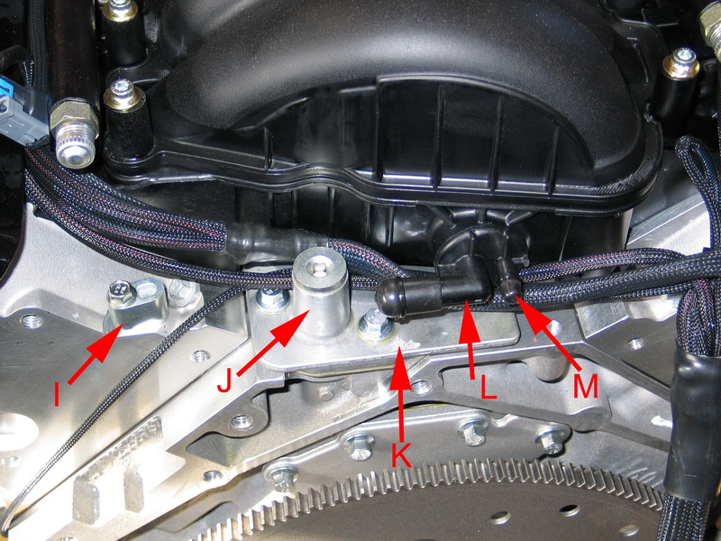 |
I = Rear cylinder head steam port blocked off. This is the same as the stock Corvette application (some Gen III/IV truck apps have all four steam ports connected). J = Oil pressure sender port, 16mm x 1.5 ORB. An adapter is included to convert this port to 1/8" NPT. K = Valley cover. L = Large manifold vacuum port. M = Small manifold vacuum port. This one is handy for connecting to the vacuum compensating port on a fuel pressure regulator. |
||||||||||||||||||||||||||||||||||||||||||||||||||||||||||||||||||||||||||||
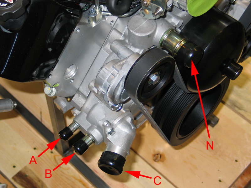 |
N = Water pump outlet (out to radiator, from engine), 1-5/16". A = Water pump outlet to heater core, 5/8". B = Water pump inlet from heater core, 3/4". C = Water pump inlet / thermostat housing (in to engine from radiator), 1-9/16". The thermostat is 180°F.
|
||||||||||||||||||||||||||||||||||||||||||||||||||||||||||||||||||||||||||||
 |
Stock air-conditioning compressor mount location bosses. For use in my buggy, I ordered my LS2 without air conditioning, but it is an available option. The LS2 a/c compressor uses its own separate serpentine belt which is driven by the innermost part of the crank pulley (which can be seen unused on my motor in the above pic). |
||||||||||||||||||||||||||||||||||||||||||||||||||||||||||||||||||||||||||||
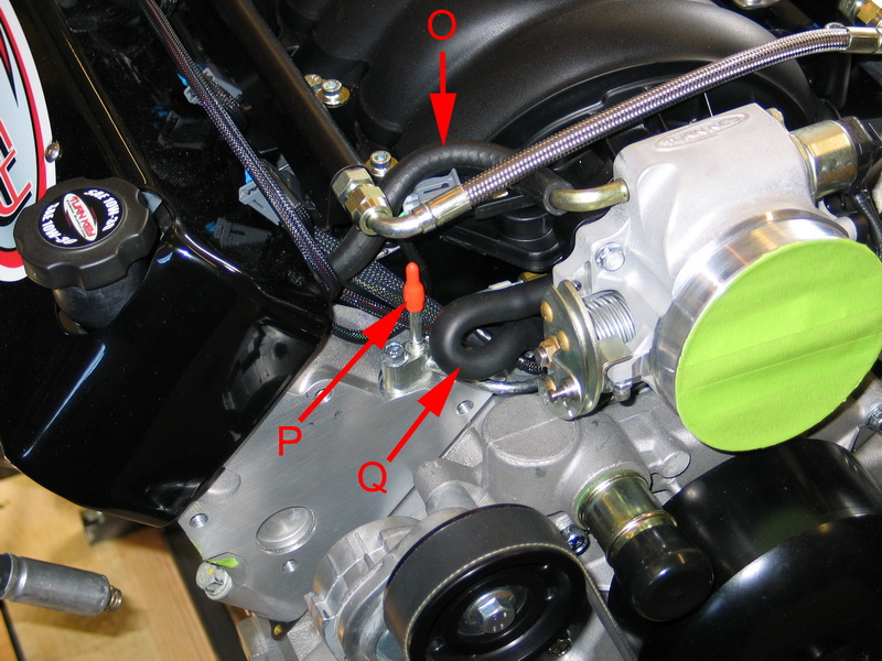 |
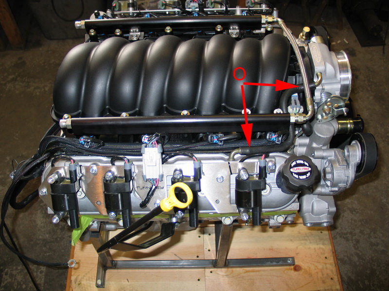
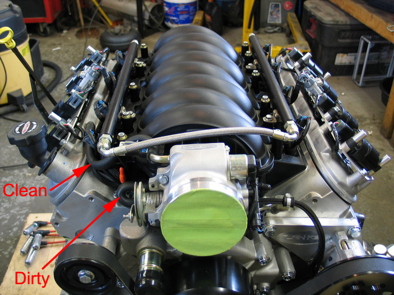
O = Clean air intake side of PCV system. Fresh, filtered air supplied from throttle body to rocker cover inlet. P = front right cylinder head steam port, connected to front left port. Also known as engine vent line or coolant vent. This will be connected to a steam port on the radiator. Q = Dirty air side of PCV system. Intake vacuum draws crankcase fumes and oil vapour out of the valley cover port and into the intake manifold. |
||||||||||||||||||||||||||||||||||||||||||||||||||||||||||||||||||||||||||||
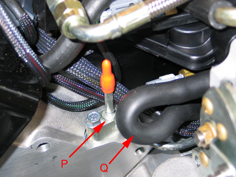 |
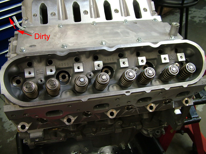
Close up of steam port and PCV hose. PCV hose is 3/8" ID. Steam port is 1/4" OD. |
||||||||||||||||||||||||||||||||||||||||||||||||||||||||||||||||||||||||||||
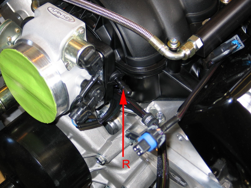 |
R = Manifold vacuum port located at front of engine. | ||||||||||||||||||||||||||||||||||||||||||||||||||||||||||||||||||||||||||||
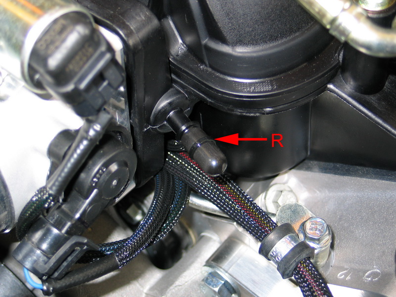 |
Close up of front manifold vacuum port. Note that all vacuum ports come securely capped should you not need to use them. | ||||||||||||||||||||||||||||||||||||||||||||||||||||||||||||||||||||||||||||
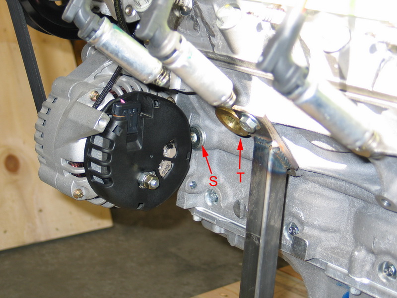 |
S = Direct port to oil galley, connects to oil galley just after the oil pump. This location is pre-filter (dirty oil) and therefore not a good place to plumb an oil accumulator. 16mm x 1.5 straight thread with crush washer. T = Engine block coolant drain plug. |
||||||||||||||||||||||||||||||||||||||||||||||||||||||||||||||||||||||||||||
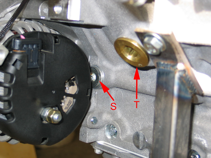 |
Close-up of oil galley port and coolant drain plug. | ||||||||||||||||||||||||||||||||||||||||||||||||||||||||||||||||||||||||||||
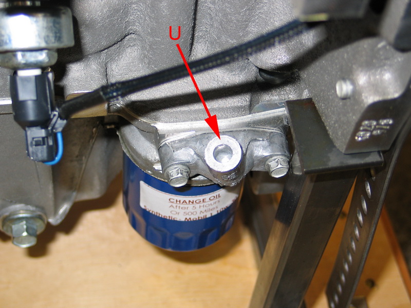
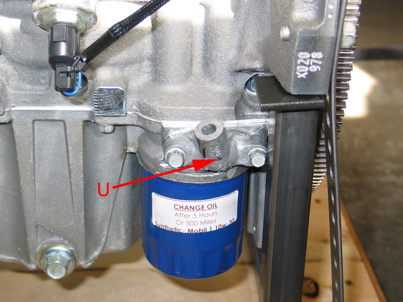 |
U = legacy oil filter bypass housing. Early Gen III motors had the oil-filter bypass mechanism located here. The oil filter bypass allows oil to bypass the oil filter and continue to circulate in the event that the oil filter becomes sufficiently plugged to cause a dangerous drop in oil pressure. If the filter becomes completely clogged with debris, the bypass opens and does not allow the filter to restrict oil flow through the engine. LS2 and other later Gen IV motors switched to an internal filter bypass, located in the oil filter, in 2007. Moving the bypass to the filter ensures that the mechanism is fresh and unobstructed each time the filter is changed. |
||||||||||||||||||||||||||||||||||||||||||||||||||||||||||||||||||||||||||||
 |
The bypass housing remains though, which is a good thing, as it can easily be drilled and tapped to 1/8" NPT and makes a good location for an oil temperature sensor. | ||||||||||||||||||||||||||||||||||||||||||||||||||||||||||||||||||||||||||||
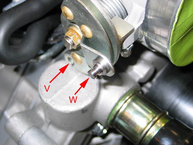 |
Throttle blade actuating arm. Throttle cable travel required for full operation is approximately 3". V = throttle cable connection. W = kickdown cable connection. |
||||||||||||||||||||||||||||||||||||||||||||||||||||||||||||||||||||||||||||
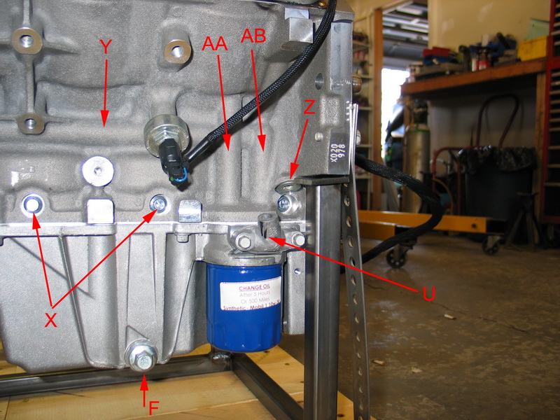 |
X = 8mm main bearing cap cross bolts. Y = Main oil galley. Z = Main oil galley port, 16mm x 1.5 straight thread with crush washer. This location is post-filter and makes an excellent location to plumb an oil accumulator - IF you can get an appropriate fitting installed without having to grind the block or filter bypass housing (U). AA = Dirty oil galley, from oil pump to filter. AB = Clean oil galley, from filter up to main feed galley (runs through the lifter bodies) and top of engine through pushrod passages. |
||||||||||||||||||||||||||||||||||||||||||||||||||||||||||||||||||||||||||||
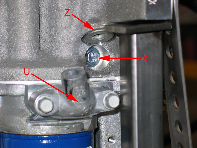 |
U = legacy oil filter bypass housing. X = 8mm main bearing cap cross bolts. Z = Main oil galley port.
|
||||||||||||||||||||||||||||||||||||||||||||||||||||||||||||||||||||||||||||
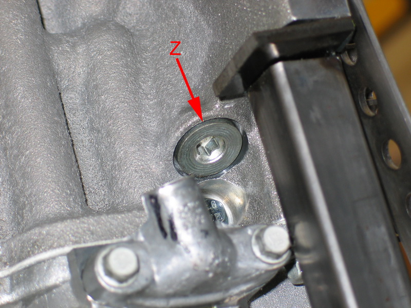 |
Z = Main oil galley port. You can see how tight it is to try and get a fitting installed in this port, especially one that converts to a male AN fitting sufficiently large for oil accumulator plumbing (i.e. AN-10 or larger). |
||||||||||||||||||||||||||||||||||||||||||||||||||||||||||||||||||||||||||||
 |
O = Clean air intake side of PCV system. Fresh, filtered air supplied from throttle body to rocker cover inlet. | ||||||||||||||||||||||||||||||||||||||||||||||||||||||||||||||||||||||||||||
 |
Motor mount bosses, left side of block. | ||||||||||||||||||||||||||||||||||||||||||||||||||||||||||||||||||||||||||||
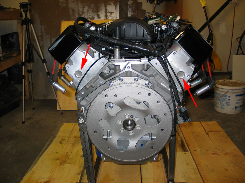 |
Red arrows indicate "cup plugs" located in the ends of the heads. Many people believe these are "freeze plugs", but they are not. The plug is installed to cover the hole. The hole is a necessary artifact from the cylinder head manufacturing process. The hole’s primary purpose was to support the water jacket core inside the cylinder head while the casting solidified in order to prevent it from floating or moving around when the molten aluminum flowed into the mold. |
||||||||||||||||||||||||||||||||||||||||||||||||||||||||||||||||||||||||||||
PCV SystemBefore we move on to the electronic fuel injection (EFI) system and its sensors, let's have a look at the LS2's PCV system in a little more detail. The purpose of the PCV system is to relieve the pressurized gasses created in the crankcase by the pumping of the pistons, scavenge these vapours and return them to the intake manifold to be combusted. In order to do this, crankcase vapours are drawn from the crankcase, up through the engine where they exit through the valley cover and are carried via an external tube to the intake manifold. this is the so-called "dirty" side of the system as the gasses contain oil vapour. Of course, if we are removing gas from the crankcase, we must also replace it. The "clean" side of the PCV system provides fresh air from the throttle body (i.e. post air filter) to a port in the right rocker cover, to replace the scavenged crankcase vapours. |
|||||||||||||||||||||||||||||||||||||||||||||||||||||||||||||||||||||||||||||
 |
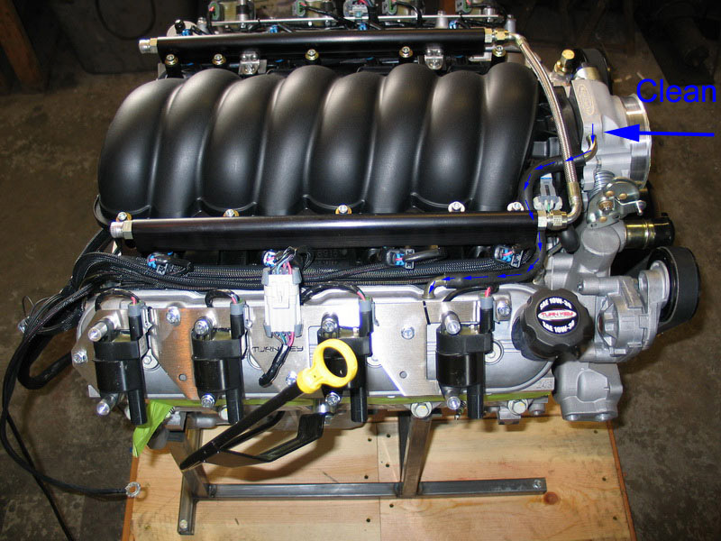
Uppermost hose is the clean side. Small, looped hose is the dirty side. |
||||||||||||||||||||||||||||||||||||||||||||||||||||||||||||||||||||||||||||
 |
LS2 PCV system air-flow illustrated. |
||||||||||||||||||||||||||||||||||||||||||||||||||||||||||||||||||||||||||||
 |
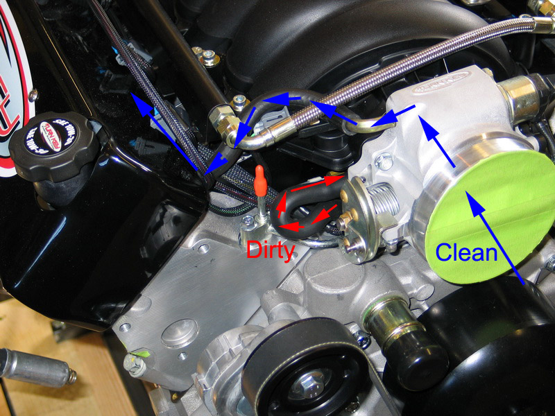
This pic illustrates the path that fresh, clean air takes in the system. | ||||||||||||||||||||||||||||||||||||||||||||||||||||||||||||||||||||||||||||
 |
This pic illustrates the port in the valley cover from which the dirty crankcase vapours are drawn. | ||||||||||||||||||||||||||||||||||||||||||||||||||||||||||||||||||||||||||||
What can't be seen in the above pics are the oil separators. Externally, the LS2 PCV system appears only to be a couple of hoses - a clean one connecting the throttle body to the rocker cover, and a dirty one connecting the valley cover to the intake. But there is more to the system than that. There are air/oil separators on both sides of the system. The most important is the dirty-side separator, as that is where the oil is in the air. Essentially, the separator is a baffling system that separate the oil from the air and drops it back into the crankcase so that only the air is burned. The better the oil is separated, the less oil will be burned, and the less oil consumption will occur. There is also a separator on the clean side. This is required because, under certain conditions (like wide open throttle), blow-by increases to the point that it exceeds the capacity of the dirty side to extract and consume the gasses. When this happens, the air flow can reverse, and air comes out of the crankcase from the clean side. Obviously, under these conditions, you don't want to dump a lot of oil into the throttle body, so a separator is also required on the clean side. Under normal conditions, this reverse-flow situation is not a problem, because the intake manifold produces enough vacuum to constantly purge the crankcase vapours adequately. There will always be some oil consumption, but it is normally very little. However, at sustained WOT and high engine speed there is no longer sufficient manifold vacuum to help pull the air from the crankcase. At the same time, more blow-by is produced. This combination may exceed the capacity of the dirty air side, which is sized for most normal light load engine operation, (if it were sized larger, the engine would consume excessive oil under normal conditions, which would not be beneficial) and reverse flow can occur. Therefore, the clean side also has a separator to ensure reverse-flow conditions don't dump oil into the throttle body. Part 5 - EFI & SensorsThe Turn Key "510" LS2 is managed and controlled by a custom-built and calibrated electronic fuel injection (EFI) system based on General Motor's Delphi Marine Electronic Fuel Injection - Fourth Generation (MEFI-4). There are several advantages to using this system instead of a re-programmed OEM road vehicle system, including:
Before we look at the Turn Key LS2 MEFI-4 system in detail, let's quickly review the basics of EFI operation, and particularly MEFI. Despite how high-tech this engine is, the fundamentals of the 4-stroke internal combustion engine haven't changed since its invention - it's still suck, squeeze, bang, blow; and the engine still needs just three things to run: air, fuel, and spark. How well it runs, and how much power it makes still depends on combining these three things in the right proportions at the right time. The first, how much air, has changed the least - as with the earliest carbureted engines, the more you step on the throttle pedal, the more the throttle blade opens, and the more air enters the engine. Simple enough. It's the other two - fuel and spark timing that have changed radically. Feeding an engine the right amount of fuel is, and has always been, basically a function of engine load - the more load on the engine, the more fuel it needs. Spark timing is basically a function of engine speed - the faster the engine speed, the earlier in the "squeeze" (compression stroke) the spark must be fired. Older engines used to rely on vacuum created by the venturi effect as the carburetors throttle blade was opened to "suck" more and more fuel out of the carb and into the intake manifold. They also used all manner of contraptions to control spark timing via a distributor - from vacuum advance to rotating mechanical counterweights. All that is gone. In today's modern EFI engines, like the LS2, fuel and spark delivery are controlled by a computer or Electronic Control Module (ECM). In the EFI LS2 fuel is delivered, or injected, directly into the cylinders by fuel injectors. Fuel injectors are nothing more than highly sensitive and accurate valves - they are supplied fuel by the fuel rail at a constant pressure, and have a calibrated orifice, or opening. The computer fuels the engine by telling the injectors when to "fire" (open and deliver fuel), and controls how much fuel is delivered by how long it tells the injector to stay open. Spark timing is similarly controlled by the computer. In the case of the LS2, which has individual ignition coils for each cylinder, the computer simply tells each coil when to "fire" and thereby create a spark across the spark-plug electrodes which, of course, ignites the fuel-air mixture in the cylinder and begins the "bang", or compression stroke, which is what makes power at the crank. Remember how we said that the amount of fuel required depends on engine load, and the spark timing on engine speed? It follows then, that the computer needs to know, or be able to measure, how much load is on the engine, and how fast the engine is turning. It gets this information from an array of engine sensors. With that information, it then "looks up" how much fuel to inject, when to inject it, and when to fire the spark for each cylinder in a set of pre-programmed tables (know as the "calibration") stored in the ECM's memory. Bottom line - the ECM accepts sensor information (inputs), then takes that data and looks up in its calibration tables, then sends signals (outputs) to control the engine, primarily to deliver the correct fuel and spark timing that the engine requires. Of course, the preceding explanation is a grossly over-simplified version, just to illustrate the basic principles. There are a host of other conditions and environmental factors, in addition to engine load and speed, that affect fueling and spark timing. Things such as temperature (of the surroundings, and of the engine), altitude, throttle position, whether the car is accelerating or decelerating, etc. all play a roll. In order to account for these conditions and deliver correct fuel and spark for all possible engine operating conditions, the ECM reads several other engine sensors and uses this data to "modify" the data it has looked up in the base calibration tables. There are different computing or calculation strategies used by different systems to accomplish this, the most common being "mass airflow", "speed-density", and "Alpha-N". Of these three, mass airflow is the most complicated, requires the most sensors, and relies heavily on a somewhat finicky and fragile air-flow sensor placed in the air inlet stream; it is commonly used in production vehicles but is not the best choice for rugged marine or off-road use. Alpha-N uses very few sensors and is little more than an electronic carburetor, relying primarily on engine rpm to decide how much fuel to add; it is normally suitable only for use in race cars that run at wide-open-throttle most of the time. The Turn Key LS2 with its MEFI-4 system uses speed-density calculation. Here's a basic look at how the specific sensors in the Turn Key LS2 with its speed-density MEFI-4 fuel injection work. Engine load is primarily determined by sensing the current engine speed and reading the manifold pressure via the manifold absolute pressure (MAP) sensor (this is similar to old-fashioned vacuum signal). The MEFI module uses RPM and MAP to select data from a table with rows and columns of numbers that represent injector pulse width values (milliseconds of on-time). When the ECM needs to know how much fuel to deliver it reads the MAP and RPM, then it refers to the corresponding row and column in its fuel table to obtain the correct injector pulse width, also known as the “base pulse width”. Once this pulse width value is obtained there are adjustments made to it based upon other engine operating conditions, however MAP and RPM are the main factors involved in selecting the base value. The engine’s spark advance is also selected in similar fashion. Again, there is a table in the ECM ’s memory with rows and columns of numbers that specify degrees of advance. The desired advance value is chosen based upon RPM and MAP. Once the desired spark advance is obtained, other operating conditions are evaluated and used to adjust the value. The conditions the Turn Key MEFI-4 system uses to adjust base pulse width and base timing include throttle position, coolant temperature, manifold air temperature, air/fuel ratio (exhaust O2), and knock detection. The complete list of Turn Key LS2 sensors and what they sense and report is as follows: MEFI-4 InputsCS - Crank Sensor (a.k.a. Crank Trigger) – crank angle (i.e. where each cylinder is in its 4-stroke cycle) & RPM. All of these sensors play a vital role in engine operation and are used by the MEFI-4 ECM to sense a variety of operating conditions. The outputs from the MEFI-4 ECM are: MEFI-4 Outputs:EST Signal (Electronic Spark Timing) - to fire the coils / spark plugs. Injector Driver - to fire fuel injectors. IAC Stepper Motor Control - Maintains perfect idle speed with the IAC stepper motor. Fuel Pump Relay - Intelligent control of the fuel pump based on fuel pressure and engine status e.g. shut down fuel pump and therefore engine on overtemp, low oil pressure, engine overspeed, etc. Check Engine Lamp - ECM turns on warning lamp when it detects a problem condition. It also stores a "diagnostic trouble code" or DTC which can be read by a scanner. Tachometer Signal - to drive the tachometer. The following series of pictures and text illustrate the location of the Turn Key LS2's MEFI-4 speed-density sensors and their primary uses. |
|||||||||||||||||||||||||||||||||||||||||||||||||||||||||||||||||||||||||||||
.jpg) |
1 = CPS – camshaft position sensor. The CPS tracks and reports the rotational position of camshaft and therefore valve/stroke timing. It is also used to detect misfires. The cam sensor is located on the front engine cover, as shown. |
||||||||||||||||||||||||||||||||||||||||||||||||||||||||||||||||||||||||||||
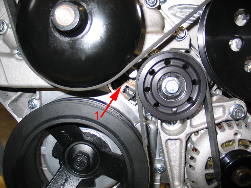 |
The LS2 uses the latest digital cam-timing technology. The CPS reads a 4X sensor target on the cam sprocket. The target ring has four equally spaced segments that communicate the camshaft’s position more quickly and accurately than previous systems with a single segment. When combined with the LS2's 58X crankshaft position encoder (located at the rear of the crank), this system ensures extremely accurate timing for the life of the engine. It also provides an effective back-up system in the event one of the two sensors fails. |
||||||||||||||||||||||||||||||||||||||||||||||||||||||||||||||||||||||||||||
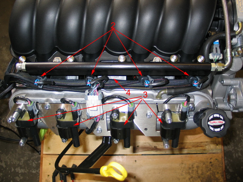 |
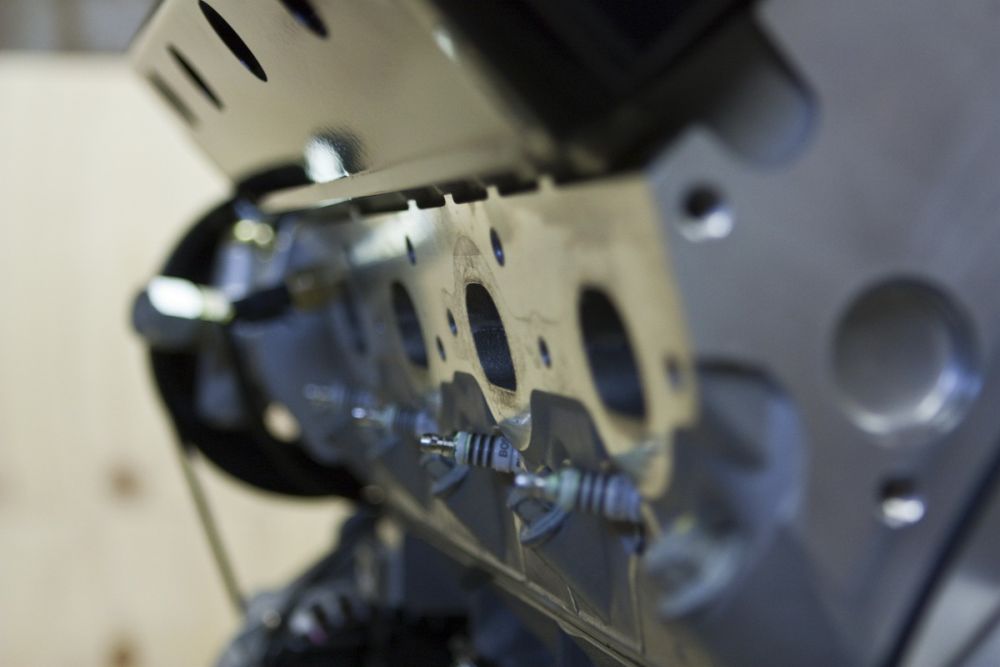
2 = Fuel injectors. 3 = Ignition coils. 4 = Firing order placard ( 1-8-7-2-6-5-4-3 )
|
||||||||||||||||||||||||||||||||||||||||||||||||||||||||||||||||||||||||||||
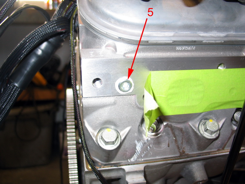 |
5 = 1/4" NPT port for electrical water temperature gauge. This port is a 12mm x 1.5mm metric fitting on the stock LS2, but on the Turn Key engine it is 1/4" NPT to match 99.9% of the gauges out there. This means that you don't have to try and make adapters or take the head off just to drill and tap for a gauge sender. |
||||||||||||||||||||||||||||||||||||||||||||||||||||||||||||||||||||||||||||
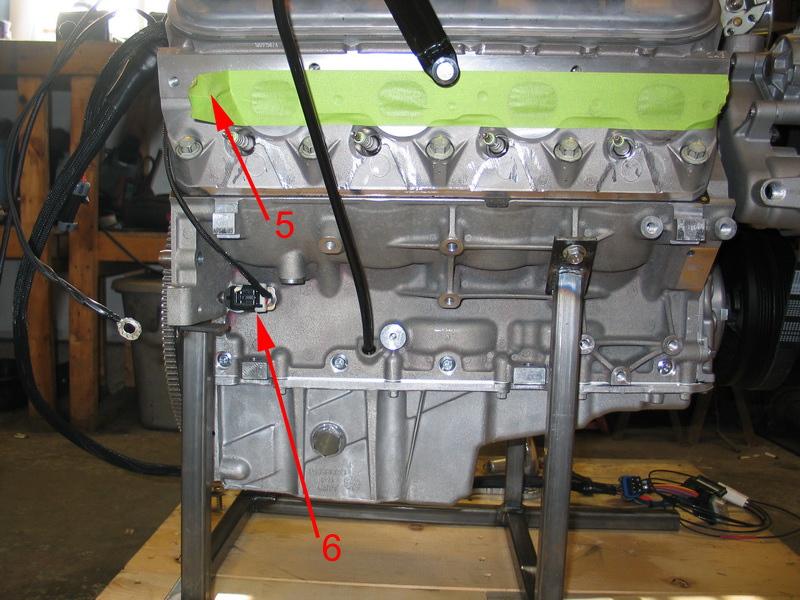 |
5 = Water temp gauge port 6 = Crank Sensor (CS). |
||||||||||||||||||||||||||||||||||||||||||||||||||||||||||||||||||||||||||||
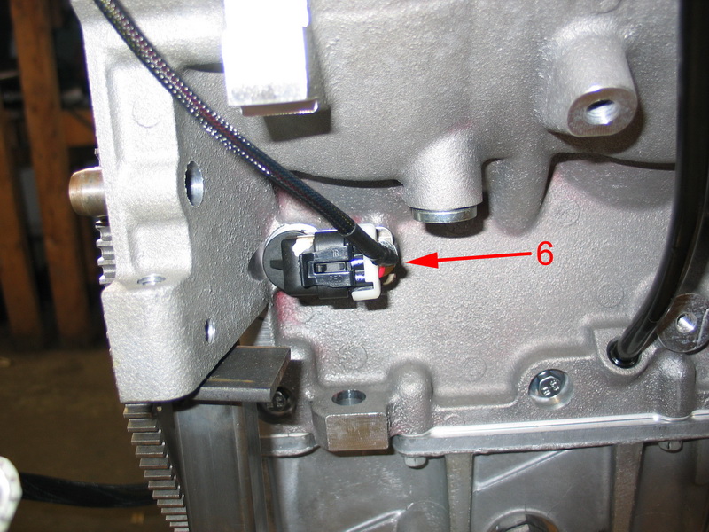 |
The CS reads the 58x crankshaft position encoder attached to the rear of the crank and thereby tracks and reports the crank angle (location) & engine RPM. Engine RPM, or engine speed, is one of the main factors used to determine injector pulse width and ignition timing in a speed-density system. |
||||||||||||||||||||||||||||||||||||||||||||||||||||||||||||||||||||||||||||
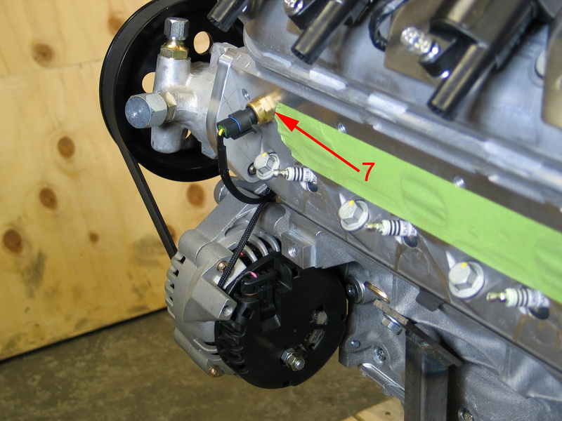 |
7 = Coolant Temperature Sensor (CTS). The CTS monitors engine temperature and tells the ECM when the engine has reached or exceeded normal operating temperature. CTS data is used in a wide range of functions, from telling the ECM when to use cold start-up enrichment mode to turning on the electric radiator cooling fans to fuel/spark adjustments and engine over-temp protection. When engine temperature reaches 235°F, the ECM goes into "limp home" mode where it limits rpm to 2000. |
||||||||||||||||||||||||||||||||||||||||||||||||||||||||||||||||||||||||||||
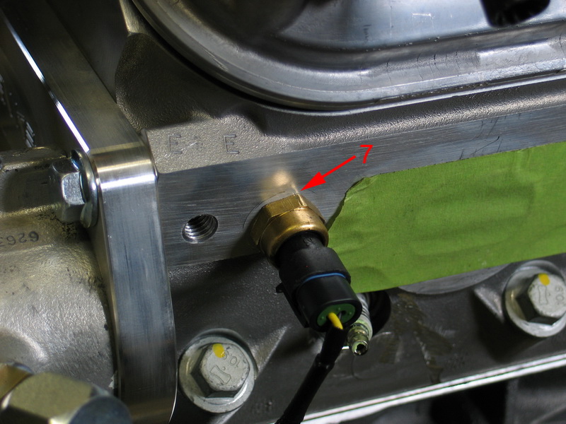 |
7 = CTS The coolant temperature sensor provides important fueling information to the ECM when the engine is below it’s normal operating temperature. Cold engines require more fuel to operate so the ECM uses the CTS information to enrich the air/fuel mixture in much the same way an automatic choke did on carbureted engines. Depending upon how cold the engine is, the ECM will increase the base pulse width values obtained from it’s main fuel table and then gradually taper off the increase as the engine warms up. The CTS is also used for several other temperature-dependent functions including: the modification of idle speed, IAC motor position, and spark advance as well as detecting engine overheat situations. |
||||||||||||||||||||||||||||||||||||||||||||||||||||||||||||||||||||||||||||
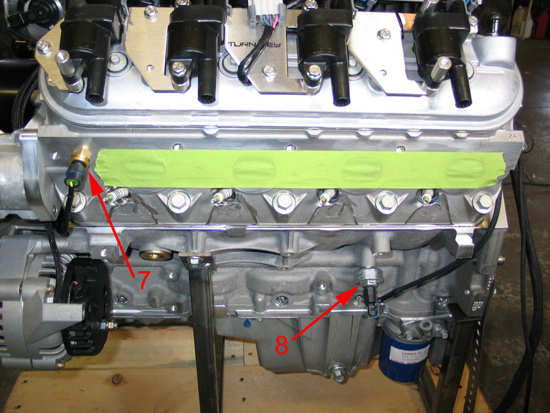 |
7 = CTS. 8 = Knock Sensor (KS). The KS detects engine knock or ping. When it detects this high-frequency vibration/sound this information is used to retard timing and prevent pre-ignition. This system protects the engine from damage caused by detonation or pre-ignition while allowing the most aggressive ignition timing advance possible. It can also serve to adapt the system to varying octane levels in different fuels, although the Turn Key LS2 is tuned and calibrated to run on premium (91+ octane) unleaded gasoline. |
||||||||||||||||||||||||||||||||||||||||||||||||||||||||||||||||||||||||||||
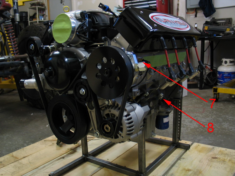 |
7 = CTS. 8 = KS. |
||||||||||||||||||||||||||||||||||||||||||||||||||||||||||||||||||||||||||||
.jpg) |
8 = KS. The KS is a critical part of the computer-controlled spark timing, as it forms the " feedback loop" in order to eliminate detonation. When the knock sensor detects detonation (or "knock") it signals the ECM to retard timing (called "knock retard"). The ECM then retards timing until detonation stops and, once it stops, advances the timing again. The loop takes only milliseconds and is continually occurring such that spark timing is always at the optimum level for best performance, highest fuel economy, lowest emissions and the octane of the gasoline being used. |
||||||||||||||||||||||||||||||||||||||||||||||||||||||||||||||||||||||||||||
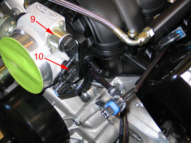 |
9 = IAC – Idle Air Control Valve. The IAC supplies metered air at idle, and the built-in sensor reports the solenoid plunger position to the ECM. 10 = TPS – Throttle Position Sensor The TPS reports the throttle blade position (or level of opening), and more importantly, its rate of change of position - i.e. is it opening, and how fast (an indication of acceleration) or is it closing, and how fast (an indication of deceleration). By monitoring the precise position of the throttle blade via the TPS, the ECM can respond quickly to driver-commanded throttle changes. |
||||||||||||||||||||||||||||||||||||||||||||||||||||||||||||||||||||||||||||
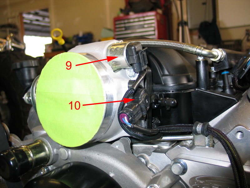 |
9 = IAC The IAC is used to add more air to the engine as it is decelerating or warming up, like a high idle cam on a carb linkage, in order to keep the engine from stalling. In this manner the IAC is used by ECM to control idle RPM. To increase RPM, the ECM commands the plunger to extend, allowing more air to bypass the throttle blade. To decrease idle RPM the ECM commands the plunger to retract, reducing or preventing air from bypassing the throttle blade. 10= TPS |
||||||||||||||||||||||||||||||||||||||||||||||||||||||||||||||||||||||||||||
| The throttle position sensor is probably the most misunderstood of all engine sensors. While readings from this sensor are important in determining idle and wide open throttle conditions (eliminating the need for mechanical switches), its main purpose is to provide information related to engine acceleration and deceleration. Under normal running conditions, above idle and less than full throttle, the MEFI-4 ECM uses "spreading" to sense if the operator is trying to rapidly accelerate or decelerate. It does this by determining how much the TPS voltage has changed since the last time the value was read. The sensor’s absolute position and corresponding voltage are less important than the amount it has changed. The MEFI-4 ECM reads the TPS voltage every few milliseconds and calculates the difference between the current and last readings. If a large enough change is detected, adjustments are then made to the fuel injector’s base pulse width value to provide extra fuel for rapid acceleration or decrease in fuel for deceleration. Again, the exact TPS voltage is important at idle or wide open throttle; however during normal running conditions it’s the change and rate of change in TPS voltage that matters most. | |||||||||||||||||||||||||||||||||||||||||||||||||||||||||||||||||||||||||||||
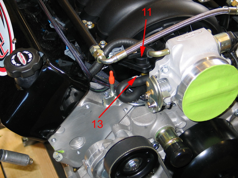 |
11 = MAP – Manifold Air Pressure Sensor The MAP senses intake manifold pressure (the opposite of manifold vacuum) and therefore engine load and altitude. 13 = IAT – Inlet Air Temperature Sensor The IAT reports the temperature of the air entering the intake manifold (and therefore also the air's density). |
||||||||||||||||||||||||||||||||||||||||||||||||||||||||||||||||||||||||||||
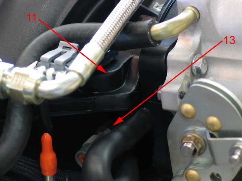 |
11= MAP The MAP measures the pressure of the air in the intake manifold as a measure of how much air is being drawn into the engine. The lower the pressure (higher the vacuum), the more air that is being drawn into the engine, and therefore the more power the engine is making and the more fuel it needs. This information is one of the key factors in the speed-density ECM's fueling calculations as it accurately represents the load on the engine. The MAP sensor allows for load correction and altitude compensation. 13 = IAT Inlet air temperature data is important in calculating the proper fueling to achieve optimum air/fuel ratio for the best performance and efficiency for the given conditions. The ECM uses the IAT data to alter fueling and timing curves which results in modifying fuel and spark delivery for changes in intake manifold air temperature. |
||||||||||||||||||||||||||||||||||||||||||||||||||||||||||||||||||||||||||||
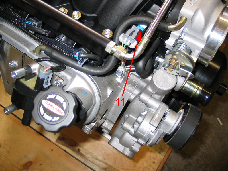 |
11 = MAP |
||||||||||||||||||||||||||||||||||||||||||||||||||||||||||||||||||||||||||||
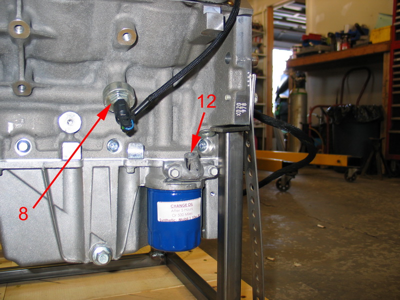 |
8 = KS. 12 = legacy oil filter bypass housing. Tapped to 1/8" NPT, this is the future home of my oil temp gauge sending unit. |
||||||||||||||||||||||||||||||||||||||||||||||||||||||||||||||||||||||||||||
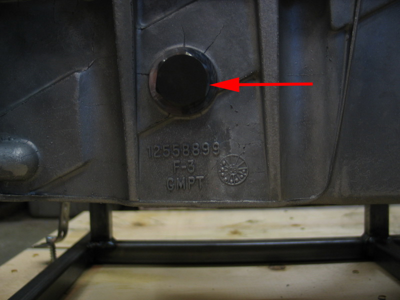 |
The red arrow indicates the plug that is used to replace the stock LS2 low-oil-level sensor, as the MEFI-4 ECM doesn't use a low-oil-level input. This is no loss at all, as this kind of sensor is designed for the "average idiot" who does no maintenance or inspection on their car. Let's face it - if you own a hi-po aftermarket engine like this and run it low on oil you probably get what you deserve. Not only that, but if left in, I might uncover this sensor when climbing or off-camber, which would cause the ECM to shut down the engine at the worst possible time, even though I would still be fine from an oiling perspective as I will be running an oil accumulator. |
||||||||||||||||||||||||||||||||||||||||||||||||||||||||||||||||||||||||||||
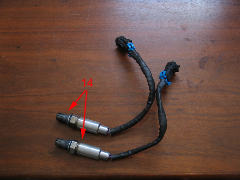 |
14 = O2 - Oxygen Sensors. When installed, the O2 sensors are located in the exhaust collectors, just after the headers. O2 sensors monitor O2 level in exhaust which the ECM uses to determine how rich or lean the air/fuel mixture is and make necessary adjustments. The O2 sensors provide a feedback loop (called closed-loop operation) for the ECM to control to the desired air/fuel ratio. The O2 sensors are the EFI systems "report cards" - they tell the ECM "how am I doing" with regards to air/fuel ratio when in closed-loop mode. |
||||||||||||||||||||||||||||||||||||||||||||||||||||||||||||||||||||||||||||
| The Turn Key LS2 with MEFI-4 goes into closed-loop feeback mode when the engine reaches approximately 122°F | |||||||||||||||||||||||||||||||||||||||||||||||||||||||||||||||||||||||||||||
 |
15 = oil pressure gauge sending unit port. | ||||||||||||||||||||||||||||||||||||||||||||||||||||||||||||||||||||||||||||
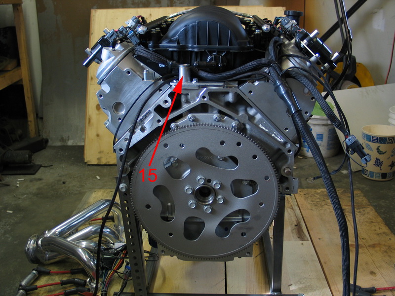 |
15 = oil pressure gauge sending unit port. | ||||||||||||||||||||||||||||||||||||||||||||||||||||||||||||||||||||||||||||
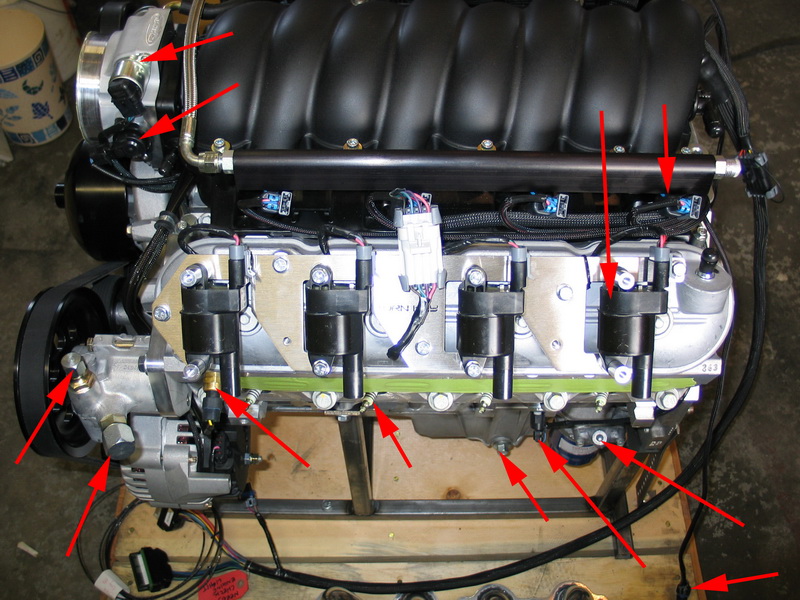 |
Test: OK, to check if you've been paying attention - name each component identified by a red arrow. You have 3.2 seconds - GO!!! |
||||||||||||||||||||||||||||||||||||||||||||||||||||||||||||||||||||||||||||
Part 6 - Included in the KitOne of the many features of a Turn Key engine package that sets it apart from all others, and one that you should definitely consider when engine shopping, is how complete the package is. Many vendors claim to sell "complete" kits with "everything you need" but very few, if any, really do - except Turn Key. Check out just what's included:
Here's a look at all the goodies: |
|||||||||||||||||||||||||||||||||||||||||||||||||||||||||||||||||||||||||||||
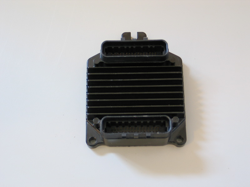 |
This is the GM-Delphi MEFI-4 ECM. It has two connectors and three mounting bosses. |
||||||||||||||||||||||||||||||||||||||||||||||||||||||||||||||||||||||||||||
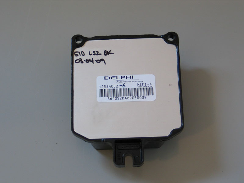 |
Back side of the ECM. Here's a neat feature of the custom Turn Key ECM programming - it is supplied with a "break-in program". The break-in program will limit initial rpm and then progressively allow more for the first 3 hours of run time. After break-in of 10 hours the ECM will provide full performance. |
||||||||||||||||||||||||||||||||||||||||||||||||||||||||||||||||||||||||||||
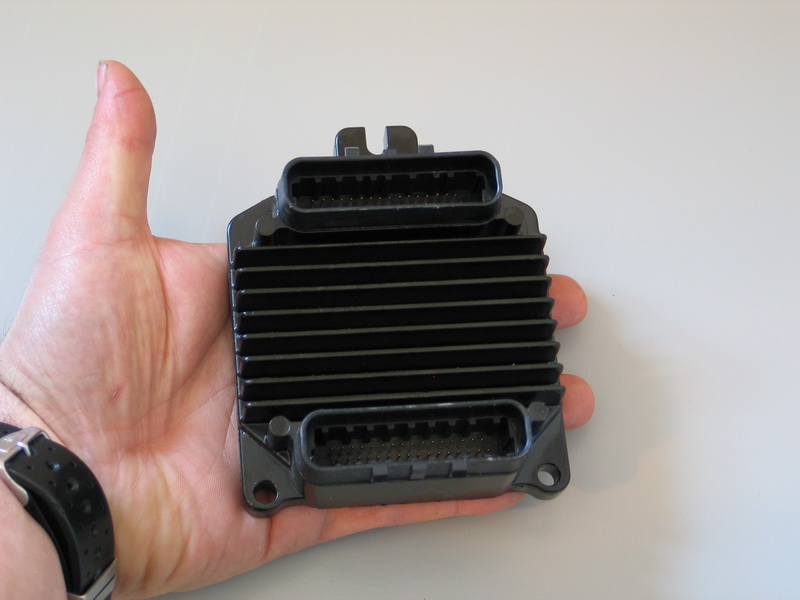 |
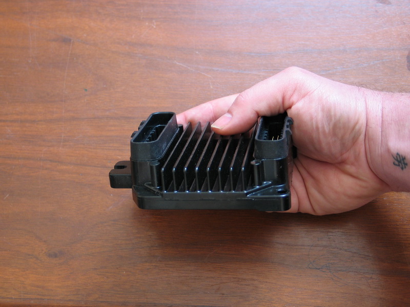
The ECM is incredibly light and compact and was originally developed specifically for the marine industry which shares a very harsh operating environment with off-road applications. |
||||||||||||||||||||||||||||||||||||||||||||||||||||||||||||||||||||||||||||
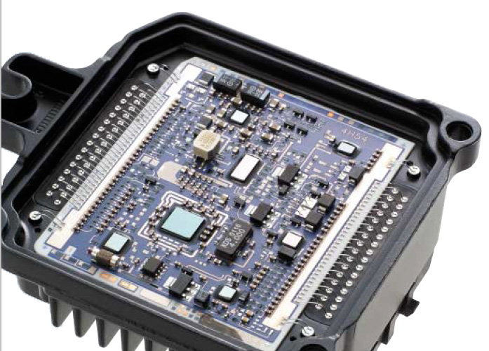 |
Inside the ECM. The MEFI-4 ECM is manufactured using a state-of-the-art, thick-film “hybrid” technology that forms the circuits by literally “printing” layers of conductive and nonconductive ink onto a ceramic substrate. The result is an extremely rugged and durable circuit board that can be mounted directly onto the engine if required, because it can handle very high temperatures and severe vibrations. |
||||||||||||||||||||||||||||||||||||||||||||||||||||||||||||||||||||||||||||
 |
Extensive use of “flip chip” integrated circuit technology The MEFI-4 ECM also "learns" as it is driven, fine-tuning its calibration / outputs in response to atmospheric conditions, engine condition, and driving style. |
||||||||||||||||||||||||||||||||||||||||||||||||||||||||||||||||||||||||||||
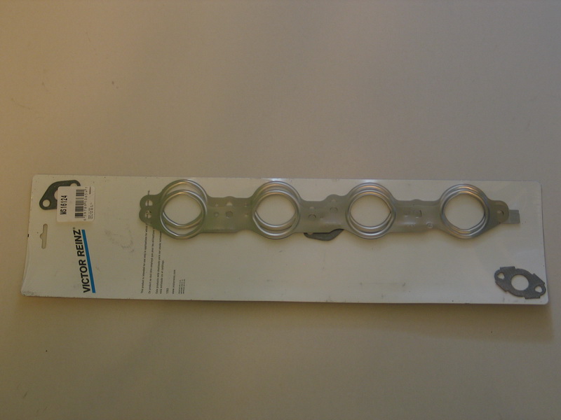 |
Victor Reinz exhaust manifold gaskets, part number: MS16124 | ||||||||||||||||||||||||||||||||||||||||||||||||||||||||||||||||||||||||||||
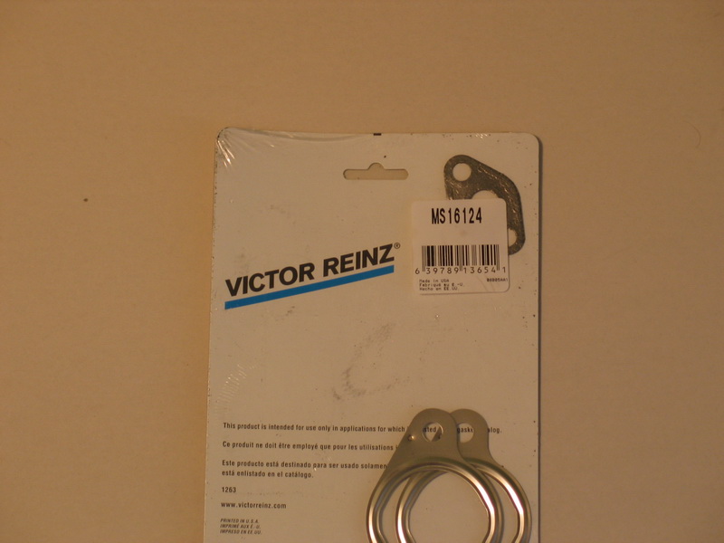 |
Victor Reinz exhaust manifold gaskets, part number: MS16124 | ||||||||||||||||||||||||||||||||||||||||||||||||||||||||||||||||||||||||||||
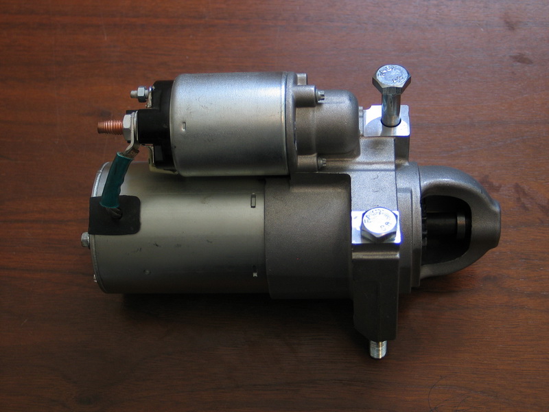 |
Starter motor and solenoid - sourced from 2002 Chevy Camaro application. Starter solenoid: Delco Remy (GM) M15AP08J Starter: Delco Remy (GM) 12588052 (M15AP0BB) |
||||||||||||||||||||||||||||||||||||||||||||||||||||||||||||||||||||||||||||
 |
Serpentine Belt. Part numbers / interchange is as follows: Bando 6PK1995 |
||||||||||||||||||||||||||||||||||||||||||||||||||||||||||||||||||||||||||||
Some other applications that use this belt are listed below, should you ever find yourself needing one in the middle of nowhere:
|
|||||||||||||||||||||||||||||||||||||||||||||||||||||||||||||||||||||||||||||
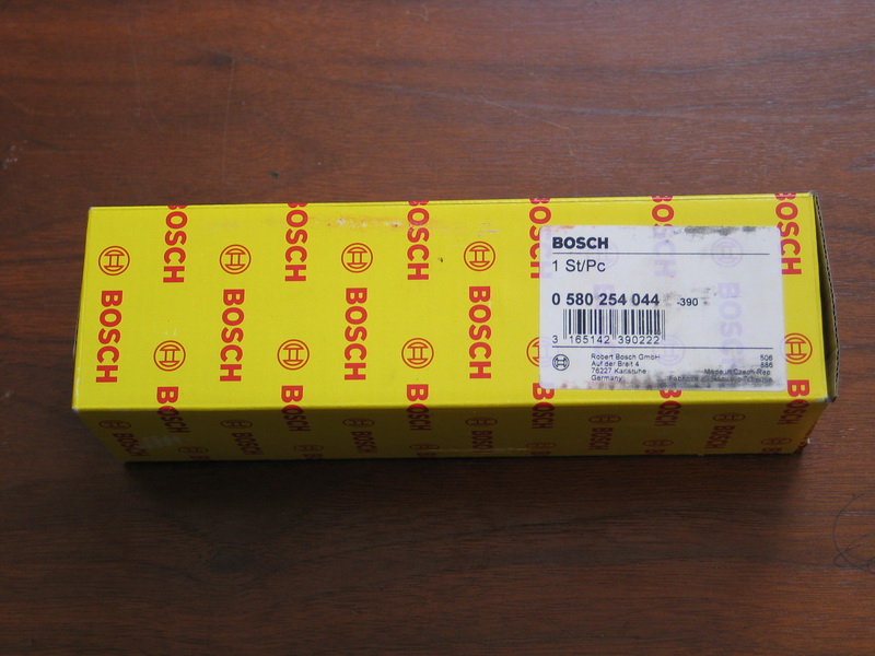 |
Bosch fuel pump, part number: 0 580 254 044 | ||||||||||||||||||||||||||||||||||||||||||||||||||||||||||||||||||||||||||||
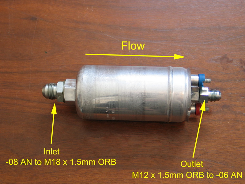 |
Bosch fuel pump showing direction of flow, electrical connectors, and the Turn Key supplied metric-to-AN fuel line adapters. | ||||||||||||||||||||||||||||||||||||||||||||||||||||||||||||||||||||||||||||
Bosch fuel pump 0 580 254 044, specifications
Note: Operating voltage = 12V, test pressure indicated are also suggested maximum operating pressures. Flow specifications achieved after initial "running in" period of 20 minutes. |
|||||||||||||||||||||||||||||||||||||||||||||||||||||||||||||||||||||||||||||
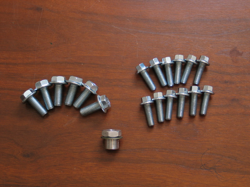 |
The larger bolts on the left are 10mm motor-mount bolts. Only six are shown as the other two come installed on the block to hold it on its custom shipping stand. The 12 smaller 8mm bolts are the exhaust manifold bolts. The adapter is the supplied oil pressure port adapter that converts the stock 16mm x 1.5 metric port at the back of the valley cover to 1//8" NPT. |
||||||||||||||||||||||||||||||||||||||||||||||||||||||||||||||||||||||||||||
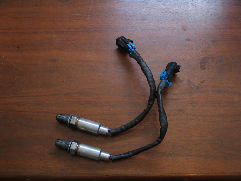 |
Oxygen sensors, AC Delco AFS 93 | ||||||||||||||||||||||||||||||||||||||||||||||||||||||||||||||||||||||||||||
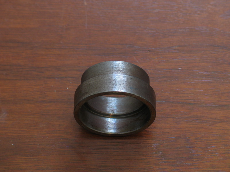 |
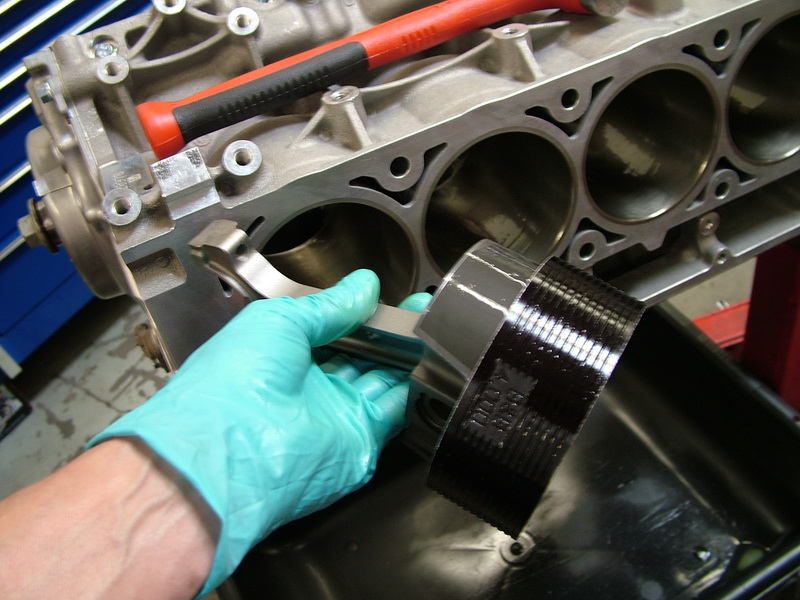
This is the crank adapter supplied so that you can mate an older automatic transmission (like my TH400) to the Turn Key LS2. | ||||||||||||||||||||||||||||||||||||||||||||||||||||||||||||||||||||||||||||
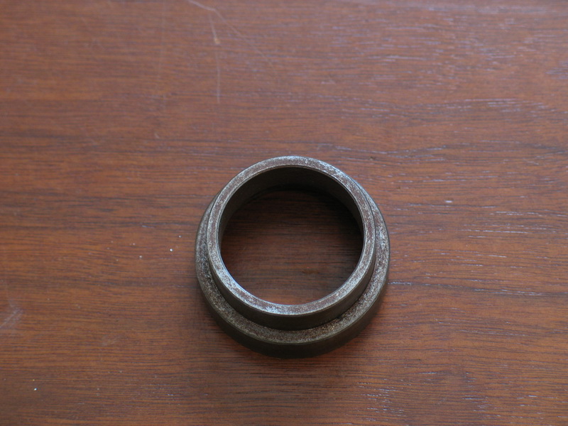 |
The adapter is required because on the Gen III/IV engines, the rear face of the crank is 0.400" shorter than on the original Gen I small blocks. Put another way, if you were to measure the lengthwise distance from the bellhousing mounting flange at the rear of the engine back to the rear face of the crank, this dimension would be 0.400" longer on the LS2 than on an old small block Chevy. |
||||||||||||||||||||||||||||||||||||||||||||||||||||||||||||||||||||||||||||
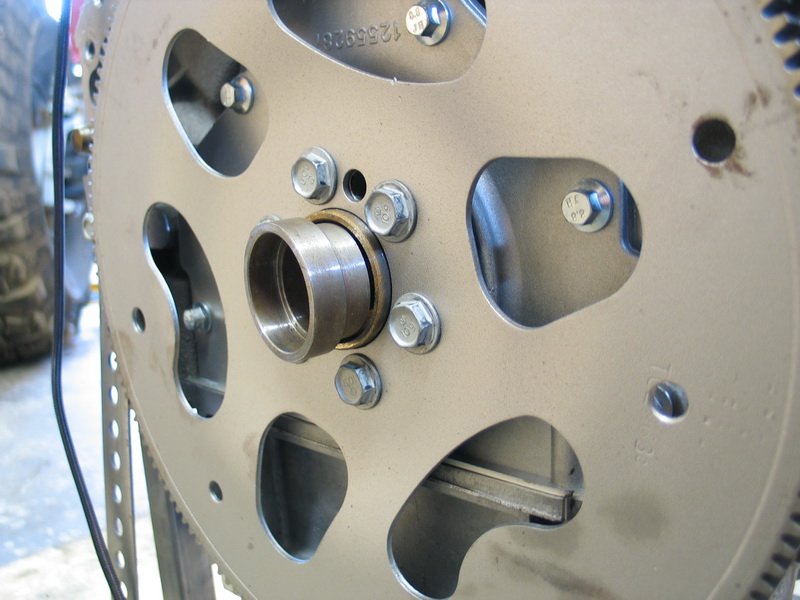 |
The supplied adapter installs in the back of the crank pilot hole to make up the difference and allow the use of standard-length older-style torque converters. If you were to leave it out and use an older transmission, the input shaft on the torque converter would not fully engage in the pilot hole in the crank. | ||||||||||||||||||||||||||||||||||||||||||||||||||||||||||||||||||||||||||||
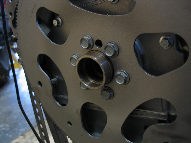 |
The adapter is made of high-strength steel and features a special tapered fit. It is installed by tapping it into place in the crank pilot hole. | ||||||||||||||||||||||||||||||||||||||||||||||||||||||||||||||||||||||||||||
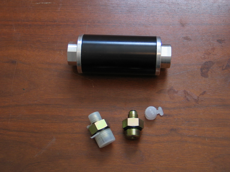 |
The TKLS2 comes with two fuel filters - a pre-pump pre-filter and a post-pump filter. The pre-filter is rated for 100 micron filtration. |
||||||||||||||||||||||||||||||||||||||||||||||||||||||||||||||||||||||||||||
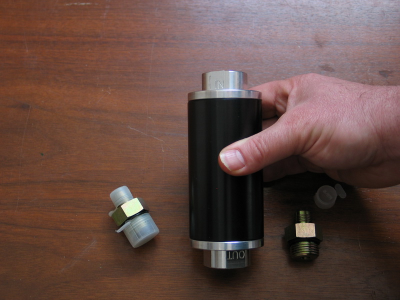 |
The post-pump filter is rated for 35 micron filtration. Both come with the necessary adapters to convert the 5/8" O-ring boss (ORB) ports on the filter body to -08 AN. Both share the same outside dimensions of: 4” body Both are fully serviceable with replaceable internal filtration elements. |
||||||||||||||||||||||||||||||||||||||||||||||||||||||||||||||||||||||||||||
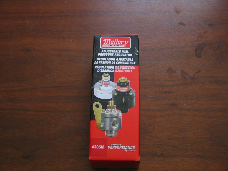 |
The supplied fuel pressure regulator is a Mallory 4305M with CNC-machined billet aluminum construction. It features flow-matched inlet and outlets, a built-in fuel pressure port, and a built-in pressure compensating (vacuum) port. |
||||||||||||||||||||||||||||||||||||||||||||||||||||||||||||||||||||||||||||
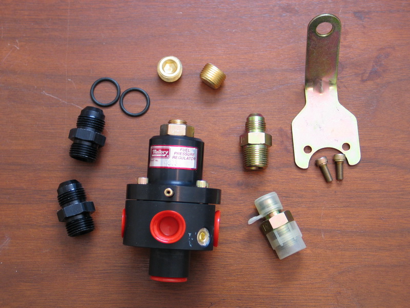 |
It comes complete with a mounting bracket, hardware, and fittings. Specifications:
|
||||||||||||||||||||||||||||||||||||||||||||||||||||||||||||||||||||||||||||
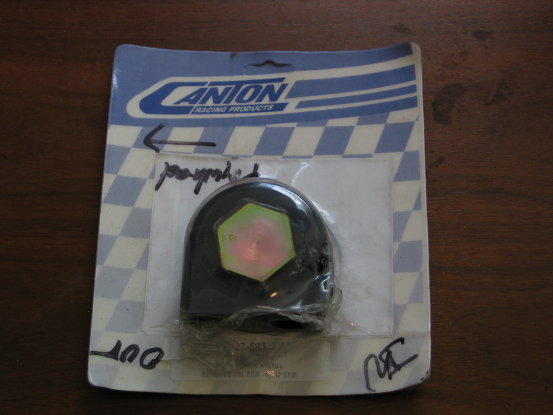 |
I plan to run an external remote-mounted oil filter as well as an oil-cooler, so Turn Key supplied this billet aluminum Canton remote oil filter adapter, part number: 22-593 (53020807). |
||||||||||||||||||||||||||||||||||||||||||||||||||||||||||||||||||||||||||||
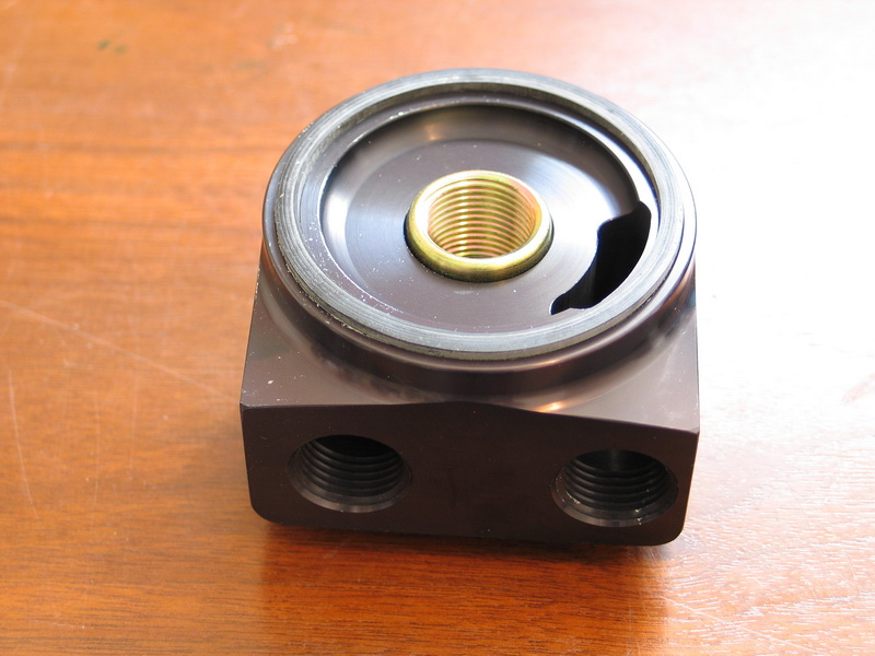 |
This 90° rotating remote oil filter adapter spins-on to the stock 13/16"-16TPI oil filter thread and seals against the pan with stock diameter 2-5/8" seal. It provides 1/2" NPT in and out ports for plumbing a remote filter. From this view, the port on the left is the INLET and the port on the right is the OUTLET. |
||||||||||||||||||||||||||||||||||||||||||||||||||||||||||||||||||||||||||||
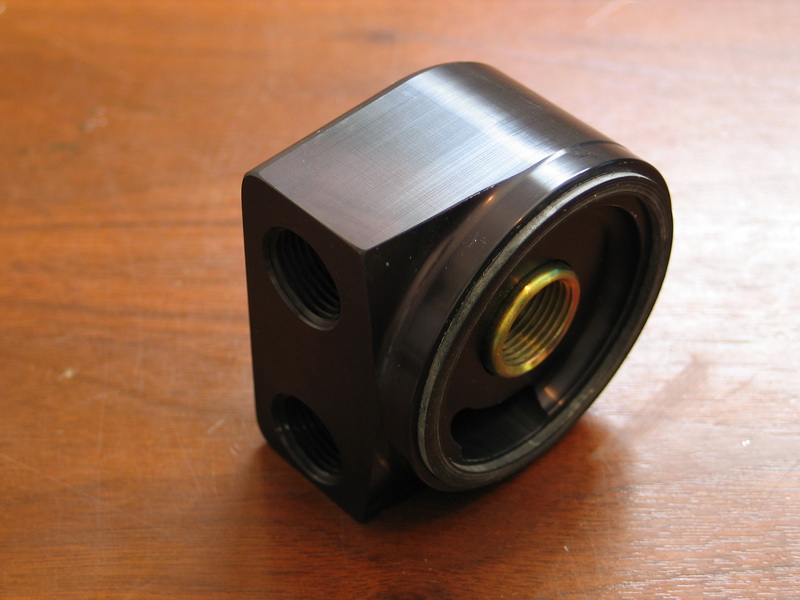 |
Its design permits it to be rotated, providing for adjustable positioning of the the two 90 degree inlet and outlet ports, which can greatly simplify plumbing. |
||||||||||||||||||||||||||||||||||||||||||||||||||||||||||||||||||||||||||||
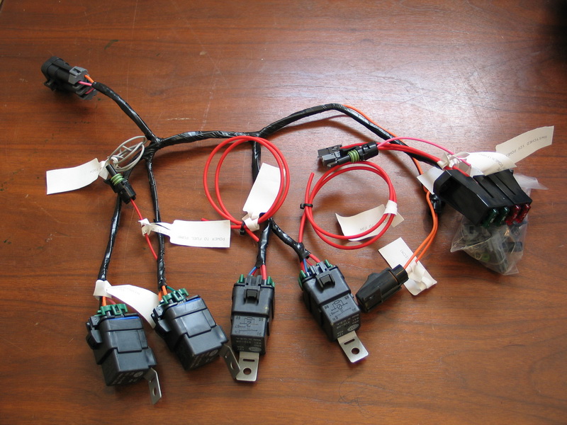 |
This is the "chassis-side" of the Turn Key LS2 wiring harness. Wiring the TKLS2 could not be easier - there are just five (5) connections to make:
|
||||||||||||||||||||||||||||||||||||||||||||||||||||||||||||||||||||||||||||
To complete the wiring, you then simply need to connect:
There are two additional connections that are optional:
The wiring harness also has a port for connecting a MEFI-4 scan tool, such as those from Rinda technologies, which are available from Turn Key. |
|||||||||||||||||||||||||||||||||||||||||||||||||||||||||||||||||||||||||||||
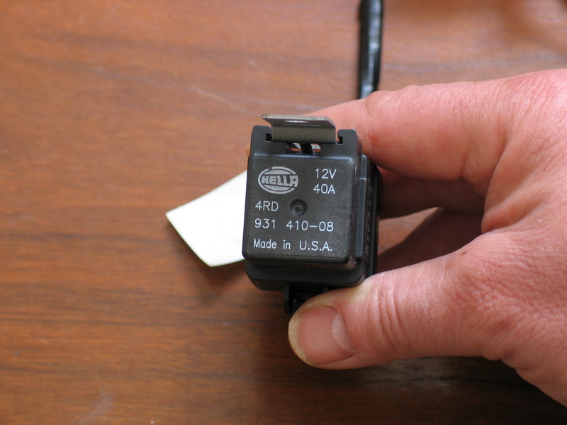 |
The fan and fuel pump relays are 12-volt DC, weather-proof, skirted, single-pole double-throw (SPDT), 40-amp Hella relays. The part numbers are:
|
||||||||||||||||||||||||||||||||||||||||||||||||||||||||||||||||||||||||||||
For the truly tech-minded, the specs on the relays are:
|
|||||||||||||||||||||||||||||||||||||||||||||||||||||||||||||||||||||||||||||
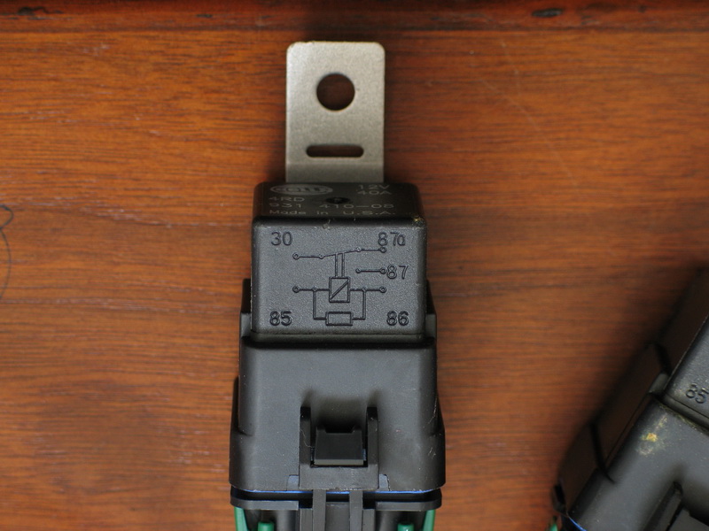 |
Pin-out diagram for the Hella relays. | ||||||||||||||||||||||||||||||||||||||||||||||||||||||||||||||||||||||||||||
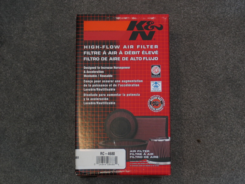 |
The supplied air filter is a K&N, part number RC-4680, round tapered universal air filter. |
||||||||||||||||||||||||||||||||||||||||||||||||||||||||||||||||||||||||||||
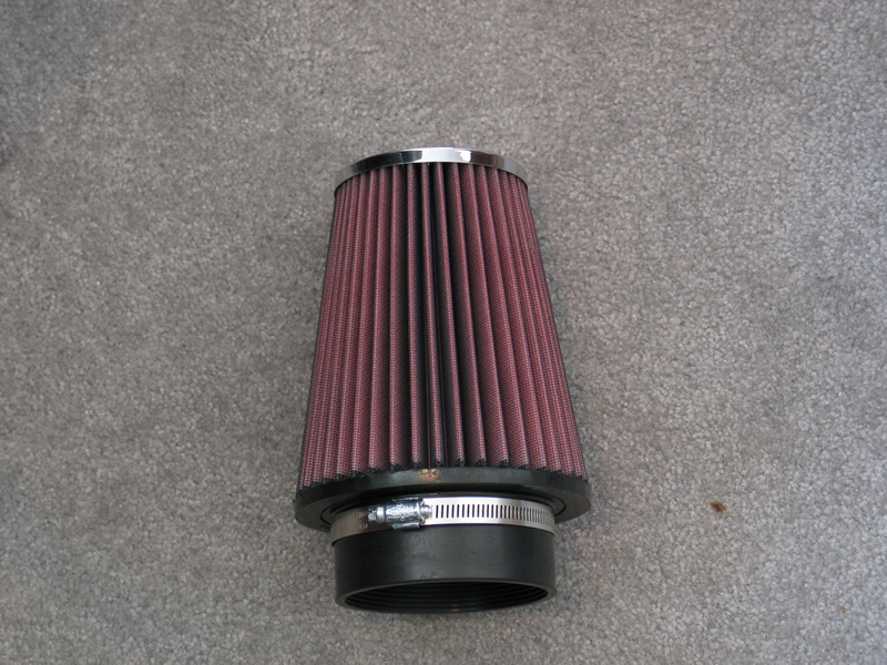 |
Specs are: Base Outside Diameter: 6 in (152 mm) |
||||||||||||||||||||||||||||||||||||||||||||||||||||||||||||||||||||||||||||
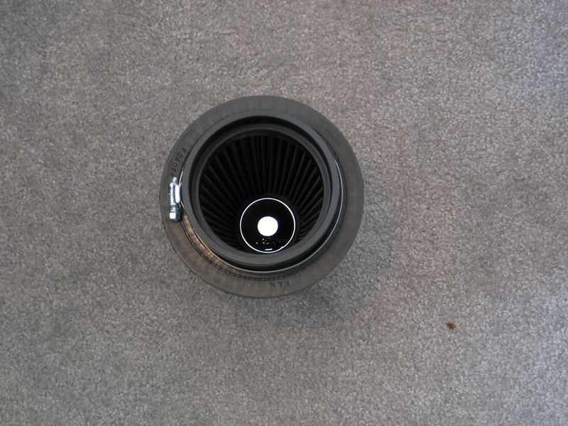 |
View inside the air filter. | ||||||||||||||||||||||||||||||||||||||||||||||||||||||||||||||||||||||||||||
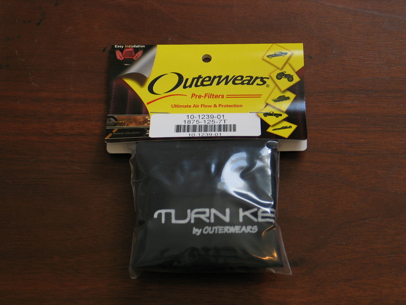 |
Also included is an air filter sock to keep the worst muck and debris off the air filter. Part number: Outerwears 10-1239-01 (1875-125-7T)
|
||||||||||||||||||||||||||||||||||||||||||||||||||||||||||||||||||||||||||||
 |
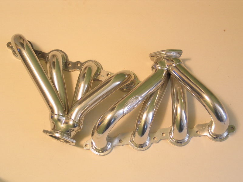
To complete the package there are Doug Thorley 326-C ceramic coated block-hugger headers. |
||||||||||||||||||||||||||||||||||||||||||||||||||||||||||||||||||||||||||||
 |
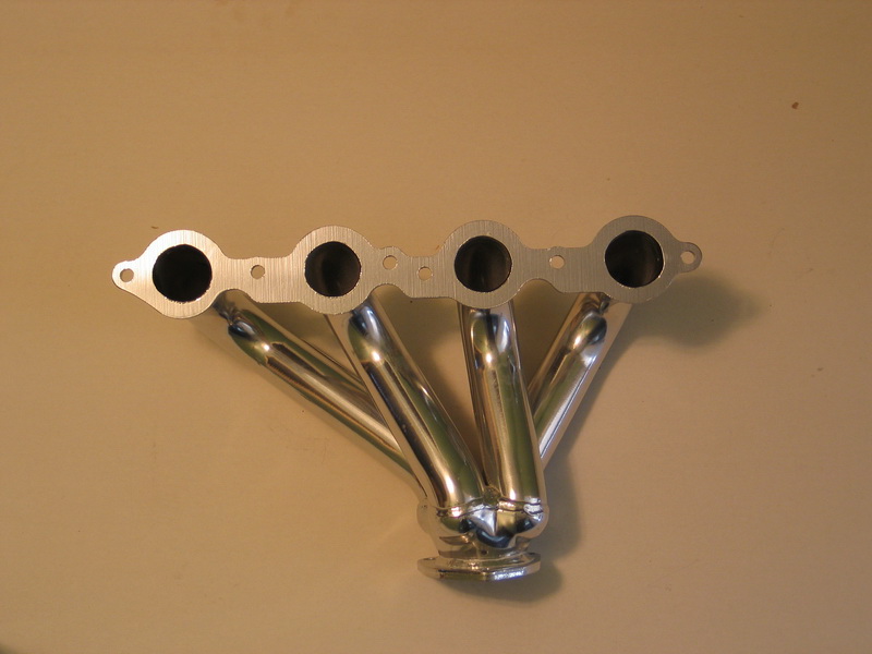
Doug Thorley 326-C ceramic coated block-hugger headers. | ||||||||||||||||||||||||||||||||||||||||||||||||||||||||||||||||||||||||||||
 |
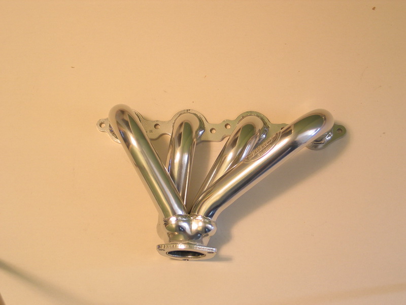
Doug Thorley 326-C ceramic coated block-hugger headers. | ||||||||||||||||||||||||||||||||||||||||||||||||||||||||||||||||||||||||||||
 |
Doug Thorley 326-C ceramic coated block-hugger headers. | ||||||||||||||||||||||||||||||||||||||||||||||||||||||||||||||||||||||||||||
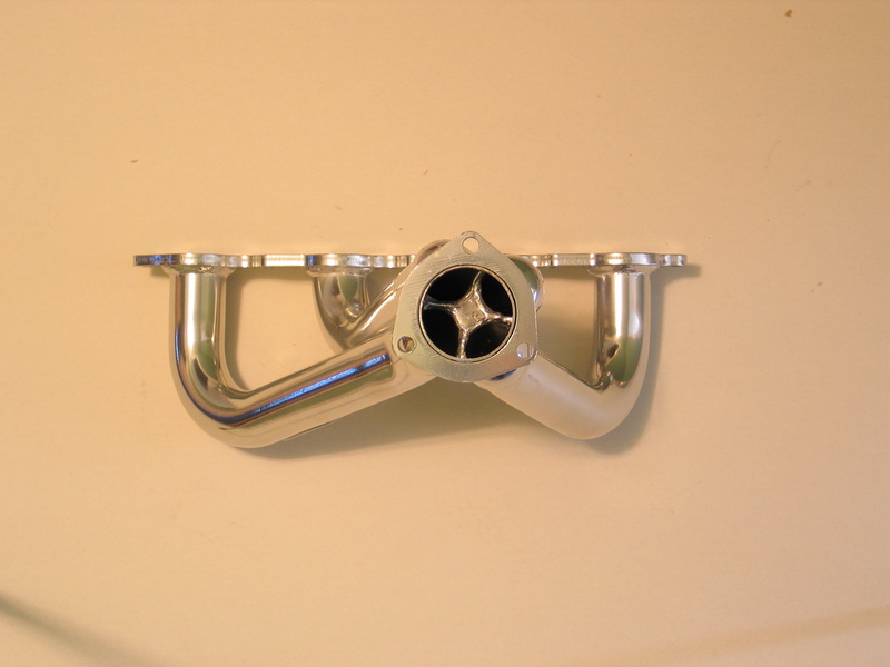 |
Doug Thorley 326-C ceramic coated block-hugger headers. | ||||||||||||||||||||||||||||||||||||||||||||||||||||||||||||||||||||||||||||
Part 7 - Turn Key Does That!So that, my friends, is the answer to the original question we posed way back at the start: "Why Turn Key Engine Supply?". As you have seen, their professional craftsmanship, knowledge, skill, care, and experience are evident in every aspect of the engine. In addition the dyno-tested performance and completeness of the package is second to none! And, of course, there's the most important reason - let me repeat it here just in case it isn't clear:
Yeah, Baby!! I should also make quick mention of some of the other things they do too:
Part 8 - InstallationI plan a separate future article to thoroughly cover the installation of my new Turn Key LS2. In this coming article we will cover the entire process, from... |
|||||||||||||||||||||||||||||||||||||||||||||||||||||||||||||||||||||||||||||
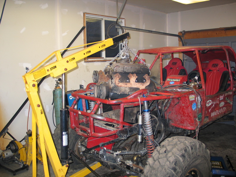 |
...yanking out the old small-block, to... | ||||||||||||||||||||||||||||||||||||||||||||||||||||||||||||||||||||||||||||
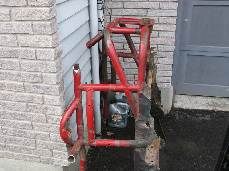 |
...chopping off the old front end, to... | ||||||||||||||||||||||||||||||||||||||||||||||||||||||||||||||||||||||||||||
 |
...staring at the big open space, to... | ||||||||||||||||||||||||||||||||||||||||||||||||||||||||||||||||||||||||||||
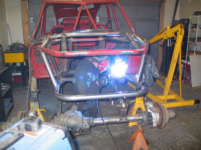 |
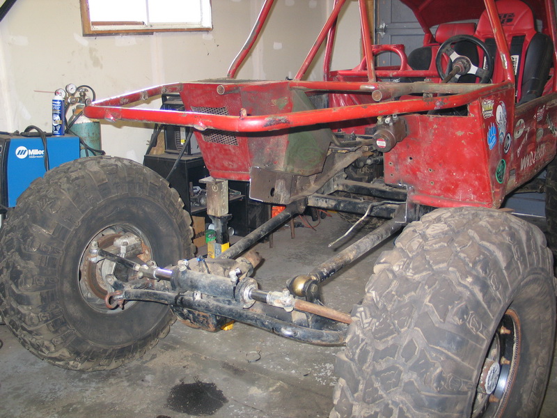
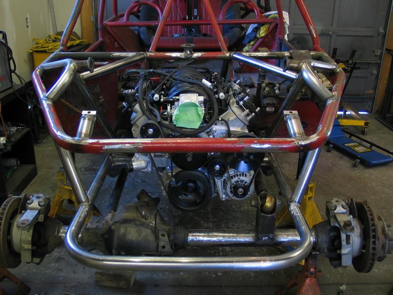
... making a new home for my baby, to... | ||||||||||||||||||||||||||||||||||||||||||||||||||||||||||||||||||||||||||||
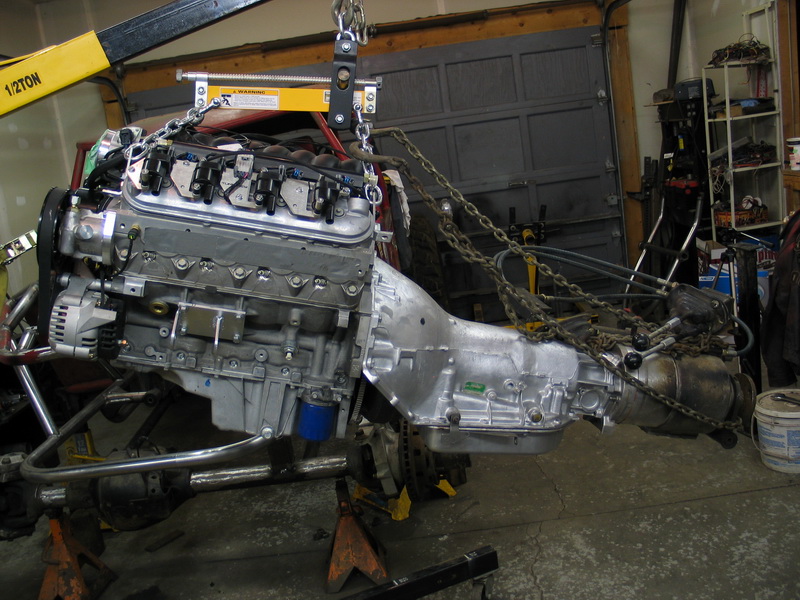 |
...installing the complete drivetrain package. | ||||||||||||||||||||||||||||||||||||||||||||||||||||||||||||||||||||||||||||
 |
So stay tuned! | ||||||||||||||||||||||||||||||||||||||||||||||||||||||||||||||||||||||||||||
Part 9 - Art!This article I will conclude with a look at some true engine art - photographs of my new Turn Key LS2 taken by good friend and photographer Lonny Handwork. Feel free to click on any pic to enlarge it and then save it as your new desktop or screen saver - nothing like leaving BIG hints for your significant other. Enjoy!
|
|||||||||||||||||||||||||||||||||||||||||||||||||||||||||||||||||||||||||||||


|
Sources: Turn Key Engine Supply 2620 Temple Heights Dr.
|


|