 |
The Coilover Bible - Part 1 By Bill "BillaVista" Ansell |
IntroductionSuspension design and engineering are extremely complex. So much so that it has been said that it would take several encyclopedia-sized volumes to cover it all, and even then there may not be more than a dozen engineers on the planet who would understand it all. That said, we can still learn a great deal from an examination of the basics; and with a firm grasp of those basics and a little testing and evaluation, almost anyone can build a decent working coilover suspension. The aim of this series of articles is to help you towards that goal. |
 |
AcknowledgementsI am enormously indebted to Benny "Bigger Valves" Langford for his assistance with the production of this article. Without his incredible wealth of technical knowledge, considerable expertise, generosity, and immense reserve of patience in answering my seemingly endless questions, it would not have been possible. For his kind support and expert advice I am profoundly grateful. Benny - you are the master and I the humble messenger - thank you! Thanks also to Frank Alioto for his kind assistance with the section on shock valving. Very Special ThanksAn undertaking of this magnitude would not be possible without the assistance of others, most notably my wonderful wife Laurie and my kids Mitchell and Jessie. To them, a huge thank you for your patience and understanding through the countless late nights. IntroductionBecause of the complexity, we will be tackling the subject of coilover tech in several parts – this is the first. In this first part we’ll be reviewing basic shock and spring tech, examining the types of coilovers and their parts, going over their use and advantages, covering the concepts of installation ratio, wheel rate, and suspension frequency, then concluding with some preliminary spring-rate selections. Future articles will cover more advanced topics such as: spring length selection and tuning, coilover adjustments / tuning, spring selection using spring force modeling, re-valving, and hands-on tech procedures such as rebuilding a shock. There is much to learn – even if you’re a seasoned coilover user as there exists a lot of misinformation about coilovers. This is because, more than with any other style of shock & spring, the coilover user is presented with almost limitless options regarding setup. Mounting, valving, spring rates, spring lengths, gas pressure and more are all completely in the hands of the installer and can be easily changed from one extreme to another. When those hands are expert – the result is phenomenal performance. When those hands are not so expert – the unfortunate result is that we novices really just have a huge amount of rope with which to hang ourselves. Instead of a huge number of ways we can tune, we are faced with a huge number of ways we can get it wrong, and sometimes badly wrong at that. To make matters worse, after we’ve unknowingly gotten it wrong (or someone else has) and we're observing the results, without a proper grounding in the basics, we lack the ability to properly interpret the results we are observing. The unfortunate result is that, instead of passing on wisdom, we unintentionally contribute to myth and misinformation. Again, without the proper grounding to accurately communicate our observations and conclusions, and despite our best intentions, we end up spreading myths and misinformation across the Internet – preventing the next hands from becoming as expert as they could be. And the cycle begins again. My aim with this article is to help break that cycle, to help your hands become just a little bit more expert, to take back some of that rope yer fixin’ ter hang yerself with. One last thing before we begin. We are going to have to be extremely clear about the definitions of the terms we use – and disciplined in their application. There are so many terms that get bantered around, often with completely different meanings, that confusion is virtually guaranteed. If nothing else, we need to agree to strive to use the correct terms, and use them consistently, to avoid adding to the confusion. A word about design philosophy. All design, including suspension design, is a compromise of factors to achieve a desired result that will be judged by some criteria. Those criteria are numerous, often subjective, and may range from cost and complexity to performance and even appearance. With this in mind, my philosophy is that there are very few, if any, absolutes – very few “rights” or “wrongs”. Some will have you think otherwise – especially the so-called “band-aid” accusers. For example, some will say that the use of an anti-roll bar is a band-aid for poor spring rate selection. Some will say that a limit-strap is a band-aid for poor link geometry. Some will say a “helper coil” is a band-aid for improper spring length. There are many other examples. In my opinion, very few are valid. There are many tools in the box of design, and if they are applied with reason and understanding, then they are certainly valid. Only if they are applied from lack of understanding of a better way do they become a concern. May this article expand your understanding so that any and all “tools” you use from the box of suspension design, you use with knowledge and confidence. Good luck! Table of ContentsSuspension ReviewAn off-road vehicle's suspension system is designed to perform these basic functions:
The first function requires no explanation. The remaining four are best illustrated by the simple example of a vehicle traveling down the trail and hitting a bump. When a tire hits a bump the wheel moves up. Without suspension this motion would be transferred directly to the chassis, causing the vehicle and it’s occupants to go up. When gravity takes over, the vehicle comes back down, and the force of the impact with the ground would again be transferred directly to the chassis and its occupants. Depending on the size of the bump, without suspension the tires could lose contact with the road, traction is lost, it would certainly be uncomfortable, the chassis would be subjected to damaging shock loads, and directional / steering control could be lost. In other words, the ride & handling would be awful.
When a rig climbs or accelerates weight is transferred from the front to the rear causing a suspension motion called “squat”. This increases the traction at the rear wheels but reduces it at the front. When a rig descends or brakes, weight shifts from the rear to the front, causing a suspension motion called “dive”, and the opposite occurs – traction increases at the front wheels and decreases at the rear. When a rig corners or side-hills, weight transfers from the inside or uphill side of the vehicle to the outside or downhill side of the vehicle, which causes a motion called “sway” or “body roll”. Without suspension, all this weight transfer would not only be incredibly uncomfortable, but depending on the severity, could quickly and easily lead to loss of traction and / or control. Enter suspension. All the components of the vehicle's suspension work together to achieve the five functions and provide the desired ride and handling. These basic suspension components are:
TiresTires are really just an air spring that supports the entire vehicle. I’ll not go into great detail about tire tuning here, but you should be aware that the tires, and the pressure in them, have a huge impact on vehicle ride and handling – regardless of the style of suspension used. This can be a complication in suspension tuning, but can also be used to advantage. For example, a stiff suspension set up for high-speed work can be made more comfortable and pliable in really rough terrain simply by adjusting the air pressure in the tires. The other reason I mention tires is because you often don’t see them mentioned when people are swapping suspension advice and experience. That’s a mistake. To properly understand and use the experience of another you need to be aware of, and account for, the type of tires they run and at what pressure. LinksFor the purposes of this article, the suspension links (or control arms) locate the axles, and define the suspension’s geometry. That is, they define the arc through which the suspension will cycle as it moves up an down. The geometry of the links also defines a host of other properties such as the vehicle’s roll axis, anti-squat, etc. Since this is not an article on suspension link design, we shall leave the discussion of links here for now, and return to them in a later part when we discuss roll and roll resistance. SpringsThe springs support the weight of the vehicle, maintain ride height, absorb road shock, and keep the tires in contact with the ground. By doing so they allow the chassis to ride relatively undisturbed while the tires follow the bumps and pot-holes in the road. There are many different types of springs, including: air springs, leaf springs, coil springs, and torsion bars. They all do the same job, with their own advantages and disadvantages. We shall be concentrating on coil springs, specifically those designed to be mounted on a coilover shock. The advantages of coil springs are numerous. They are:
When a wheel hits a bump, a force is applied to the wheel. That force causes a vertical acceleration of the wheel – the wheel goes up. The springs will absorb the load by compressing, converting the kinetic energy of the wheel’s motion into potential energy stored in the now-compressed spring. This potential energy is then released, causing the spring and wheel to rebound.
What is needed, then, is some sort of energy-converting device to assist the springs – something that can damp the compression and rebounding of the spring. Enter the shock absorber, or shock. ShocksShocks control spring motion, that is, they slow down and reduce the magnitude of the spring’s oscillation. The process is known as damping. In technical terms, a shock controls the frequency and amplitude of the suspension's oscillation. In layman’s terms, a shock controls how fast and how much the suspension compresses and rebounds. This: a) is important in keeping the tires in firm contact with the road (providing handling); and b) helps isolate the passengers from road shocks (providing a good ride). By damping the movements of the suspension, the tires remain in contact with the trail surface. This prevents the tires from bouncing and skipping with every bump and dip in the trail. Tires that do not stay in contact with the trail can’t provide good traction, steering stability or braking friction. Damping the movements of the suspension also results in resistance to vehicle bounce, roll, and sway during weight transfer and therefore resistance to brake dive and acceleration squat. How Shocks WorkA shock absorber is basically a hydraulic piston pump that converts the energy of motion (kinetic energy) into heat energy. One end of the shock, the shock body or “tube”, is the cylinder of the pump, the other end of the shock is the rod and piston. One end of the shock is connected to the chassis and the other end is connected to the suspension. As the wheels move up and down relative to the chassis the piston pumps up and down in the cylinder. The cylinder (shock body) is a tube filled with hydraulic oil. When the piston pumps up and down through the hydraulic oil, the oil is forced through holes in the piston, called orifices. The flow of the oil through the orifices is further regulated by the deflection of special spring-loaded metering valves, or deflection discs, located on either side of the piston. |
|||||||||||||||||||||||||||||||||||||||||||||||||||||||||||||||||||||||||||||||||||||||||||||||||||||||||||||||||||||
 |
Assembled shock. Cylinder (shock body) is uppermost, rod (shock shaft) protrudes below. |
||||||||||||||||||||||||||||||||||||||||||||||||||||||||||||||||||||||||||||||||||||||||||||||||||||||||||||||||||||
 |
Rod and piston being removed from cylinder. | ||||||||||||||||||||||||||||||||||||||||||||||||||||||||||||||||||||||||||||||||||||||||||||||||||||||||||||||||||||
 |
Rod and piston being removed from cylinder. | ||||||||||||||||||||||||||||||||||||||||||||||||||||||||||||||||||||||||||||||||||||||||||||||||||||||||||||||||||||
 |
Rod and piston removed from cylinder. | ||||||||||||||||||||||||||||||||||||||||||||||||||||||||||||||||||||||||||||||||||||||||||||||||||||||||||||||||||||
Because of the valves and the fact that the piston orifices are so small, only a small amount of fluid, under great pressure, passes through the piston as it pumps up and down. The resulting resistance slows down the piston and creates heat from friction. This in turn slows down spring and suspension movement and converts the spring’s kinetic energy to heat in the oil that is then dissipated as the oil cools. The amount of damping a shock absorber provides depends on the number and size of the orifices in the piston as well as the valving. By changing the design of the valves, the pressure at which they open and close can be altered and a shock’s damping characteristics can be tuned as needed. The higher the opening pressure, the firmer the shock. The lower the opening pressure, the softer the shock. Obviously, shock absorbers must work in two directions - compression and rebound. The compression stroke occurs as the shock gets shorter and the piston travels into the cylinder. The rebound stroke occurs as the shock lengthens and the piston extends from the cylinder. The compression stroke controls the motion of the vehicle's unsprung weight, while the rebound stroke controls the heavier sprung weight. Accordingly, a typical car or light truck shock will have valving designed to provide more resistance during rebound than compression. |
|||||||||||||||||||||||||||||||||||||||||||||||||||||||||||||||||||||||||||||||||||||||||||||||||||||||||||||||||||||
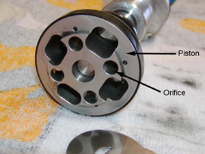 |
Close-up view of shock piston. (photo courtesy of Dan Dibble) |
||||||||||||||||||||||||||||||||||||||||||||||||||||||||||||||||||||||||||||||||||||||||||||||||||||||||||||||||||||
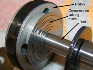 |
Compression valving discs are on the rod-side of the piston. (photo courtesy of Dan Dibble) |
||||||||||||||||||||||||||||||||||||||||||||||||||||||||||||||||||||||||||||||||||||||||||||||||||||||||||||||||||||
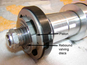 |
Rebound valving discs are on the free-end of the piston. (photo courtesy of Dan Dibble) |
||||||||||||||||||||||||||||||||||||||||||||||||||||||||||||||||||||||||||||||||||||||||||||||||||||||||||||||||||||
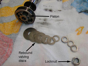 |
Rebound valving discs removed from free-end of the piston. Looking very much like a series of washers (and often referred to as such) they are stamped spring steel deflection discs that react to pressure and velocity to meter, or regulate, the amount of fluid that flows through the piston and thus the amount of resistance or damping the shock provides. A particular number, size, and arrangement of valving discs is often referred to as a "shim stack". (photo courtesy of Dan Dibble) |
||||||||||||||||||||||||||||||||||||||||||||||||||||||||||||||||||||||||||||||||||||||||||||||||||||||||||||||||||||
Heat and Shock FadeBecause of the tiny orifices in the piston, the viscosity of the shock oil has a large effect on the resistance the oil presents to the piston’s movement, and hence the damping the shock provides. Viscosity changes with temperature –hot oil is “thinner” and pours more easily than cold oil (which is why you change your oil when the engine is warm). It stands to reason then, that to provide consistent damping, we would want the shock oil to maintain a consistent viscosity. However, we just said one of the purposes of the shock is to dissipate the spring’s kinetic energy by converting it to heat that is absorbed by the hydraulic oil, so we can see the potential for trouble here. If the shock is used hard enough, it will eventually heat the oil to a point where its viscosity changes (becomes less). This thin, overheated shock oil now offers less (possibly much less) resistance to the piston’s movement, and the shock’s damping capability is reduced – sometimes drastically. This is called “shock fade.” There are strategies to combat shock fade that we will cover shortly. Shock DesignMost shocks produced today are either of twin-tube or mono-tube design. Before we look at each individually, let’s look at another important aspect of modern shock design that is often applied to both twin-tube and mono-tube shocks – gas charging. Gas ChargingThe primary function of gas charging is to minimize aeration and foaming of the hydraulic fluid by reducing the chance of cavitation. When the shock cycles, the motion of the piston through the oil creates an area of high pressure ahead of the piston and an area of low pressure behind it. If the pressure of a fluid is reduced below its vapour pressure, the fluid will spontaneously change state from a liquid to a gas. This means that tiny air bubbles can form in the low-pressure area directly behind the piston. The process is called cavitation. Left unchecked, the tiny air bubbles that form will mix with the oil - a process called aeration. The resultant mixture of oil and air inhibits the functioning of the shock as the piston and valving are designed to produce the required damping by operating in a column of incompressible oil. Once the oil is mixed with air, or aerated, it is no longer incompressible. The faster the piston pumps up and down, the more rapidly cavitation aerates the oil on both sides of the piston, and eventually the oil will be churned into foam. The resulting foam offers little resistance and causes extreme fade of the shock’s damping ability. The addition of pressurized nitrogen gas to the shock helps to prevent the low-pressure zone behind the moving piston from falling below the vapour pressure of the oil, reducing the chance of cavitation, aeration, foaming, and eventual fade. In addition to reducing foaming and fade, the gas charge allows greater flexibility in valving design. Without the gas charge, valving design would have to be compromised to allow for the possible eventual aeration of the oil. |
|||||||||||||||||||||||||||||||||||||||||||||||||||||||||||||||||||||||||||||||||||||||||||||||||||||||||||||||||||||
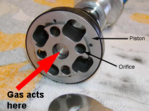 |
Depending on the pressure used and the diameter of the rod, gas charging can also cause the shock to provide a small increase in the spring rate of the suspension (in fact, if the vehicle were light enough, the rod diameter large enough, and the pressure high enough, the pressurized nitrogen alone could act as the spring – hence airshocks, but I digress). This mild boost in spring rate is caused by the pressurized gas acting on the rod through which there are, obviously, no orifices; as shown at left. Therefore, the larger the rod is in diameter, the larger the area for the pressure to act against. This gas pressure acting on the rod through the centre part of the piston is also the reason why an uninstalled, unloaded, gas-charged shock absorber will extend on its own. | ||||||||||||||||||||||||||||||||||||||||||||||||||||||||||||||||||||||||||||||||||||||||||||||||||||||||||||||||||||
Despite the effective spring rate of the pressurized shock, in a normal hydraulic shock, pressure should probably not be used to compensate for incorrect spring rates or worn / broken springs. However, it can help reduce body roll, sway, brake dive, and acceleration squat compared to a vehicle with identical springs but non-gas-charged shocks. Twin-tube Design |
|||||||||||||||||||||||||||||||||||||||||||||||||||||||||||||||||||||||||||||||||||||||||||||||||||||||||||||||||||||
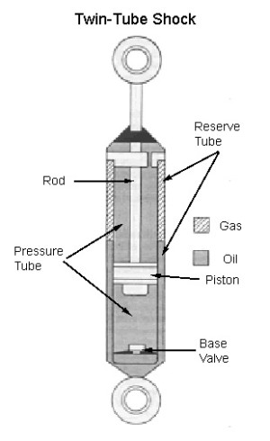 |
Most modern OEM passenger vehicle shocks are of the twin-tube design. The twin tube design has an inner tube known as the working or pressure tube and an outer tube known as the reserve tube. The pressure tube holds the oil through which the piston moves. However, because the oil is incompressible, it must have somewhere to go during shock compression as the piston rod displaces a certain volume of fluid. The reserve tube provides a place for this hydraulic fluid that is displaced as the rod travels into the pressure tube. The reserve tube also creates a space for the fluid as its volume expands due to heat during use. The reserve tube may also contain a low-pressure charge of nitrogen. The pressure of the nitrogen in the reserve tube normally varies from 100 to 150 psi. Twin-tube shocks have a valve located at the bottom of the pressure tube called the base valve. The base valve is the compression valve - it controls fluid movement during the compression stroke of the shock by metering the flow between the pressure tube and the reserve tube. Because they use a “tube within a tube”, twin-tube shocks are compact in length, making them easy to fit or package, particularly on OEM cars where space is extremely limited. Their design also lends itself to relatively cheap mass production while retaining effective performance without requiring the strict tolerances (and associated manufacturing costs) of a mono-tube design. |
||||||||||||||||||||||||||||||||||||||||||||||||||||||||||||||||||||||||||||||||||||||||||||||||||||||||||||||||||||
Twin-tube shocks also have some limitations. They tend to trap heat within the pressure tube as it is insulated from cooling air by the outer reserve tube, making them prone to heat buildup and fade under hard use. Because the base valve is inside the pressure tube they are also not designed for the user to be able to alter or customize the valving. Finally, gas-charged twin-tube shocks can only be mounted in one orientation – they will not function properly if mounted upside down. Mono-tube Design |
|||||||||||||||||||||||||||||||||||||||||||||||||||||||||||||||||||||||||||||||||||||||||||||||||||||||||||||||||||||
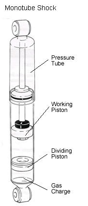 |
Mono-tube shocks have only one tube, the pressure tube. They are longer than twin-tube shocks because the single pressure tube must have sufficient length to store the hydraulic oil that is displaced as the rod travels into the pressure tube as well as provide space for the fluid as its volume expands due to heat during use. If a mono-tube shock is gas charged, as most are, it must also have a place to store the high-pressure nitrogen charge. There are two methods of accomplishing this. In some shocks, the nitrogen is stored with the oil in the pressure tube. The gas and the oil are, in effect, mixed together in an emulsion. Not surprisingly, this style of gas-charged mono-tube shock is known as an emulsion shock. A better way to contain the nitrogen charge is to separate it from the oil with a floating piston, also called a dividing piston. The floating piston moves up and down as the piston moves up and down in the cylinder, keeping the oil and nitrogen from mixing. However, the shock must now be much longer because the tube must be of sufficient length to accommodate the full stroke of the piston, all the hydraulic oil, the heat expansion of the oil, the gas charge, and the floating piston. If the shock is a long-travel shock, (meaning the piston stroke alone is 12 inches or more), the total tube length required can become prohibitive. In this case, an external reservoir is used to house the nitrogen charge, the floating piston, and some of the hydraulic oil. Mono-tube gas charges normally range from about 150 psi to 350 psi. |
||||||||||||||||||||||||||||||||||||||||||||||||||||||||||||||||||||||||||||||||||||||||||||||||||||||||||||||||||||
A mono-tube shock does not have a base valve. Instead, all of the valving during both compression and extension takes place at the piston. Since the piston and rod are easily removed from the shock, the mono-tube design lends itself to independent tuning of the compression and rebound damping by providing for easy valving changes by the end-user. As a result, mono-tube shock users can individually customize their valving for improved ride and handling. In addition, non-emulsion mono-tube shocks can be mounted in any orientation, including upside down. Because a mono-tube shock doesn’t require a “tube-within-a-tube”, for a given outside diameter, a mono-tube shock will have a larger bore, and thus be able to use a larger piston than a twin-tube design. This can be beneficial when designing a shock to extract the maximum possible damping from the smallest diameter package. Mono-tube design also allows the heat in the oil to transfer directly to the outer surface of the shock body, which is in direct contact with cooling airflow, where it can dissipate more efficiently. This reduces heat-induced fade, allowing the shock to maintain full damping characteristics as temperatures rise with hard use. Finally, mono-tube shocks must be designed and built to exacting tolerances in order to function properly. This results in a high-quality product. |
|||||||||||||||||||||||||||||||||||||||||||||||||||||||||||||||||||||||||||||||||||||||||||||||||||||||||||||||||||||
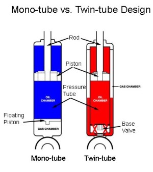 |
In the mono-tube shock, note the larger diameter piston, and the floating piston. In the twin-tube shock, note the "tube-within-a-tube" construction and the base valve. (Diagram courtesy of Polyperformance) |
||||||||||||||||||||||||||||||||||||||||||||||||||||||||||||||||||||||||||||||||||||||||||||||||||||||||||||||||||||
Shock DiameterThe larger a shock is in diameter, the larger its bore can be. The bore is the diameter of the piston and the inside diameter of the pressure tube. The larger the piston’s diameter, the larger its surface area. Since pressure is force divided by area, it stands to reason that the larger the area, the smaller the pressure generated by a given force. Inside a shock, the lower the pressure, the lower the temperature. In addition, a larger diameter shock can contain more oil to absorb and dissipate the heat generated, resulting in reduced internal operating temperatures for a given force. The result is, the larger the shock diameter, the cooler it will run and therefore the harder the shock can be worked before fading. Variable Damping / ValvingIn street / track driving, maximum performance demands shocks that provide both firm, crisp handling and a smooth comfortable ride. In offroad rigs we have the additional demands of soaking up small and large bumps at speed while allowing a degree of flexibility for slow crawling. No environment is as demanding of shocks as offroad racing. A shock with relatively stiff valving can provide firm, responsive handling and control roll, dive, and squat. But stiff valving creates ride harshness and increases feedback to the driver through the suspension. Conversely, a shock with relatively soft valving smoothes out the bumps, roughness and vibration, and allows great flexibility but can fall short of the required suspension control required for responsive handling and damping the pounding experienced in high-speed offroad driving. One solution to this apparent dilemma is to use adaptive, or variable, damping - that is, valving that adapts automatically to changing road / trail conditions. There are different strategies, all aimed at perfecting that magical balance between ride and handling for a wide range of driving conditions. Among the more common strategies are:
Each have their particular strengths and weaknesses, but they all operate on a similar principle: variable valving senses some condition and changes to react to that condition – be it the speed of the shock stroke, the position of the shock in its stroke, or some other factor. Theoretically, the shock can therefore adjust to changing road or trail conditions and deliver improved suspension control and better handling without increasing ride harshness. Velocity sensitive damping involves valving changes that occur in response to the speed, or velocity, of the shock’s stroke. This strategy provides relatively soft valving for driving on smooth surfaces, but when the wheel hits a bump, the sudden change in piston velocity causes the velocity sensitive valve to open, altering the damping to control the suspension’s oscillation. The same thing happens when the wheel rebounds from the bump. When the driving surface smoothes again, and the piston velocity slows, the valve closes and the shock's damping automatically alters for greater ride comfort. The reason I say "alters" instead of saying it gets "softer" or "stiffer" is because the precise details get quite complicated. For example, when the valves open or close, depending on the shock and valving design, the rate at which the damping becomes softer or stiffer per unit of shock velocity increase depends on if the valving is linear, progressive, or digressive. As the name suggests, in linear valving the rate at which the damping changes with the velocity of the shock is constant. If the valving is progressive, the rate of change of stiffness increases as velocity increases; and if the valving is digressive, the rate of change of damping gets less as the shocks velocity increases. Whether the valving is linear, progressive, or digressive depends on several factors including the particular shim stack and piston design. The specifics are beyond the scope of this article, but will be explored in greater detail in a later issue. For now, the key point is that velocity sensitive valving alters the shocks damping depending on the velocity of the rod and piston; it is simple, effective, and fairly rugged which makes it popular in motorsports and is the form of variable valving of most interest to off-road coilover users, albeit sometimes in combination with some form of internal or external bypass valving, described below. The disadvantage to velocity sensitive damping is that the velocity of the piston often slows as it reaches the limit of its stroke, just before it changes direction (the same way the velocity of a ball thrown in the air slows to zero at the peak of its height before it begins to fall). The problem is, it may be that, at this point of maximum stroke (rebound or compression), the shock needs more damping, not less. One approach to mitigating this limitation is to use position sensitive damping. Position sensitive damping takes a slightly different approach. Instead of using valving that opens and closes in response to piston velocity, the shock’s pressure tube is specially modified. Several small grooves are machined into the side of the pressure tube to create a different "zones" in the shock’s travel. The grooves create a leak path for oil to bypass the piston when the shock is operating in a particular zone. By carefully controlling the size and location of these internal grooves, more or less oil can be allowed to bypass the piston in different zones, increasing or decreasing damping as required. A shock using this strategy is often called an "internal bypass" shock. A typical example used in street cars has grooves machined in the normal operating midrange of the shock’s travel, creating a "comfort zone". Oil is allowed to bypass the piston when the shock is operating in this comfort zone,resulting in less damping and a softer ride. When the piston travels more than a few inches in either direction, as it does when the wheels hit a bump, it goes past the grooves and damping increases to control the suspension. Inertia sensitive damping is still another strategy. One manufacturer has developed what it calls an "inertia active system" that it says continuously meters the rebound stroke and can instantly switch from firm to soft as conditions dictate. When high rebound damping is needed, as when cornering or braking hard on a smooth surface, the inertia valve is closed. This "closed-valve" (stiff) state is the normal default condition in which handling is greatly improved. When low rebound damping is needed, as when a wheel hits a bump or pothole, the inertia valve opens to reduce damping. The system is designed to allow the wheel to better follow the terrain and the suspension to absorb jolts without transmitting them to the chassis for a smoother ride. A similar strategy is acceleration sensitive damping. With this strategy, a specialized compression valve is used. This compression valve is a mechanical closed-loop system, which opens a bypass to fluid flow around the compression valve when it senses a bump in the road, automatically adjusting the shock to absorb the impact. As soon as the impact is overcome, the valve closes and returns to the normal setting. It is claimed the valve can react in 15 milliseconds and that it operates anytime an impact or acceleration of 1.5 g’s or more is experienced. This ability to instantly switch from firm to soft is claimed to provide a noticeably smoother ride as well as better handling. Externally adjustable bypass shocks No matter what the strategy or the claims of the manufacturer; each variable damping strategy is in itself a compromise of sorts. The current pinnacle of variable damping shock design, the externally adjustable bypass shock, attempts to maximize performance and minimize compromise by blending velocity sensitive piston valving with position sensitive external bypass tubes. The piston valving uses velocity sensitive metering valves (deflection discs) but the shock also uses external bypass tubes that function in a similar manner as the internal grooves of a position-sensitive shock – they allow precisely metered amounts of oil to bypass the piston. Because the bypass tubes are external to the pressure tube, they are easily adjusted to vary the amount of bypass. The result is a shock that combines the best properties of velocity and position sensitive damping with the provision for quick and easy external adjustment. Depending on the number, size, and location of the bypass tubes, a vast amount of shock tuning is possible. Normally, when using external bypass tubes, the first 2/3rd's of the shock’s compression stroke can be lightly damped to soften the ride while the last 1/3rd is stiff to keep the suspension from bottoming. On the rebound stroke, the first 1/3rd is stiff to control the rebounding spring and stop the vehicle from bouncing while the last 2/3rd's can be lightly damped to allow the wheels to droop quickly before the next bump.
CoiloversA coilover shock is a high quality mono-tube shock that includes provisions to mount coil springs on the shock. The springs and shock are therefore combined in a single, compact package. There is nothing particularly magical about coilover shocks – their use requires strict attention to mounting geometry, spring rates, and shock valving the same as any other system. However, they do offer a number of advantages:
Don’t worry if not all of those statements make complete sense to you at this stage – they will by the end. Let’s go over the different types of coilovers and then dig in to the parts and their functions. Most coilover shocks will fall into one of the following three categories:
|
|||||||||||||||||||||||||||||||||||||||||||||||||||||||||||||||||||||||||||||||||||||||||||||||||||||||||||||||||||||
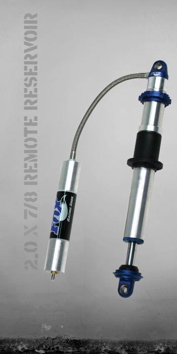 |
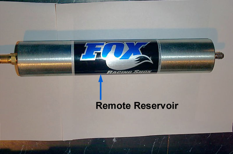
Remote Reservoir coilover shocks are the most common. They are nitrogen-charged mono-tube shocks and are commonly available with up to 18” of travel. They use a remote reservoir to house the nitrogen charge and floating piston, allowing the use of a shorter tube than would otherwise be necessary. The reservoir is connected to the pressure tube with a short, flexible hydraulic hose. Swivel fittings and different length hoses are easily installed providing flexible mounting options for the reservoir. Depending on the position of the piston in its travel, there will also be a certain amount of oil in the remote reservoir. Theoretically, depending on the mounting location of the remote reservoir, this could provide a slightly improved cooling capability – but this is not the primary purpose of the remote reservoir. Then again, if the reservoir is mounted too close to a heat source (engine, exhaust) this could cause a detriment to cooling. (Photo courtesy of Fox Racing Shox) |
||||||||||||||||||||||||||||||||||||||||||||||||||||||||||||||||||||||||||||||||||||||||||||||||||||||||||||||||||||
 |
A piggyback coilover shock is identical to a remote reservoir shock except that the reservoir, instead of being attached to the shock with a flexible hydraulic hose, is mounted directly on the shock with a bracket that incorporates the necessary hydraulic passage between the cylinder and the reservoir. Because of this they can be more of a challenge to fit. Technically, both a remote reservoir shock and a piggyback shock can be mounted upside down and still work – although there’s no reason to do so and every reason not to, as the reservoirs would be very vulnerable in that position. (Photo courtesy of Fox Racing Shox) |
||||||||||||||||||||||||||||||||||||||||||||||||||||||||||||||||||||||||||||||||||||||||||||||||||||||||||||||||||||
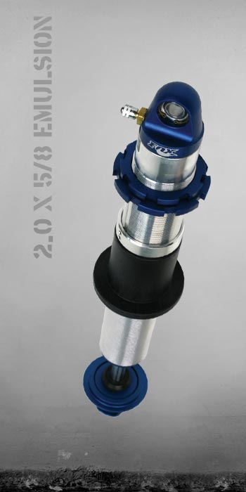 |
An emulsion coilover shock has no reservoir and no floating piston. It is still a gas-charged mono-tube shock, but the nitrogen charge is contained in the pressure tube along with the oil in an emulsion. Less resistant to aeration, foaming, and fade than the external reservoir styles, they are best suited to light weight and / or low-speed use. They are more compact and therefore easier to fit than the other styles. Also more economical than the other styles, they are usually adequate for rockcrawling use. An emulsion shock can only be mounted right side up. (Photo courtesy of Fox Racing Shox) |
||||||||||||||||||||||||||||||||||||||||||||||||||||||||||||||||||||||||||||||||||||||||||||||||||||||||||||||||||||
There are also a few non-emulsion, non-reservoir mono-tube coilover shocks available on the market. This style incorporates the reservoir and the floating piston into the main shock tube, and is sometimes called an "internal reservoir" shock. They are normally available only in shorter to medium travel (up to about 14") as so much cylinder length is required to internally accommodate the reservoir and floating piston. This style of coilover is most commonly seen for application (make / model) specific replacement or upfit. Shock diameterMost styles and brands of coilover are available in either 2” of 2.5” diameter. This is the diameter of the pressure tube or shock body. 2.5” shocks are larger and heavier than 2” shocks. Their larger diameter can make them more of a challenge to fit without limiting clearance between tire and chassis / fender. 2.5” shocks are also more expensive. Either shock can be valved the same, but the larger 2.5” shock will run cooler. Having said that – this is really only important for lengthy higher-speed desert or rock racing type use, as rockcrawling, street use, and trail riding are unlikely to overheat a 2” shock. The 2” shock uses 2.5” ID springs and the 2.5” shock uses 3” ID springs. 3” ID springs are heavier, more expensive, and their availability in numerous different rates (particularly lighter rates favoured by rock crawlers) is more limited than the smaller 2.5” ID springs. Coilover OperationThere are a great number of tuning and adjustment factors to consider when using coilovers, which we shall discuss in detail shortly. For now, it is sufficient to understand that a coilover shock with springs mounted functions as a unit that provides both springing and damping. One end of the shock has a fixed, integrated spring seat and is mounted to the axle or suspension. The other end, which incorporates an adjustable upper spring seat, is mounted to the chassis. The springs are installed over the body and shaft of the shock between the fixed lower spring seat and the adjustable upper spring seat. Springs of many different lengths and rates can be accommodated, which combined with the ability to alter the shock's internal valving, gives a wide range of tuneability. Since the shocks have a great deal of travel (to permit the large amounts of wheel travel needed for offroad use) a great deal of spring travel is also required to prevent the springs from bottoming before the shock. In order to achieve the necessary spring travel a very long spring is required. However, because there is a practical limit to how long a spring can be made before it will tend to buckle, multiple springs are stacked in series on the shock (one on top of the other) in order to achieve the required spring length. |
|||||||||||||||||||||||||||||||||||||||||||||||||||||||||||||||||||||||||||||||||||||||||||||||||||||||||||||||||||||
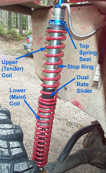 |
The most common configuration consists of two springs stacked together in series, and is called a "dual-rate" system as frequently the two springs have different rates. The upper spring is called the "tender" spring or coil, and the bottom spring is called the "main" spring or coil. (From this point forward I shall use the terms "spring" and "coil" interchangeably.) A nylon sleeve, known as the dual-rate slider (DRS), "floats" on the body of the shock between the two springs. As the springs compress and rebound, the dual-rate slider slides up and down the shock body. When multiple springs are stacked in series in this manner, the result is a variable spring rate that begins as the (normally softer) rate of the combined springs and progresses to the (normally stiffer) rate of just the main spring. The rate is initially soft because both springs are compressing together. When the springs compress far enough, the DRS slides up until it hits the stop ring and is prevented from sliding further. At this point, the dual rate slider effectively becomes the upper spring seat, locking out the upper spring. From this point, remaining spring travel occurs at the rate of the lower, main spring alone. We shall discuss dual-rate systems in great deal, including relevant formulae later. For now it is sufficient to know that stacking multiple springs gives us the required spring length and allows us to use a softer initial spring rate that transitions to a firmer rate at some point in the suspension's travel. |
||||||||||||||||||||||||||||||||||||||||||||||||||||||||||||||||||||||||||||||||||||||||||||||||||||||||||||||||||||
With a basic grasp of how they operate, let's now examine the coilover shock and it components in detail. (Note: As we've discussed, because a non-emulsion mono-tube shock can be mounted either way up, technically there is no "top" or "bottom" , "upper" or "lower" to the shock. However, the normal method of mounting the shock is with the cylinder up, attached to the chassis. This protects the cylinder and reservoir from damage. There is no practical reason to mount the shock the other way up. In addition it will make my life as a writer, and yours as reader, an awful lot easier and less complicated if we agree at the outset that the "top" or upper-end of the shock is the body- or cylinder-end, and that the "bottom" of the shock is the shaft- or rod-end.)
|
|||||||||||||||||||||||||||||||||||||||||||||||||||||||||||||||||||||||||||||||||||||||||||||||||||||||||||||||||||||
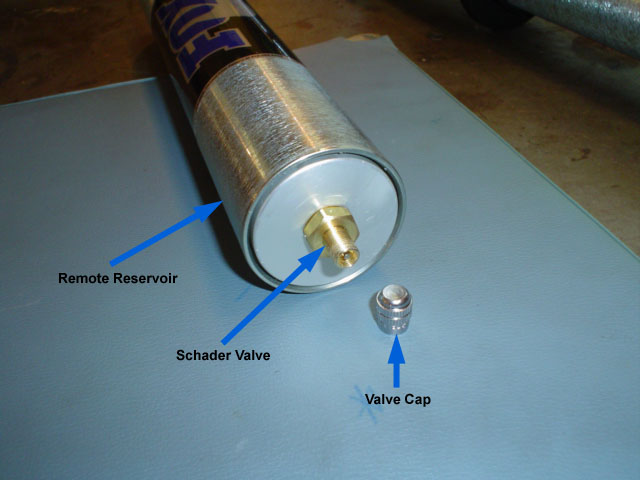 |
The Schrader valve, located at the end of the remote reservoir is used to charge the shock with nitrogen. | ||||||||||||||||||||||||||||||||||||||||||||||||||||||||||||||||||||||||||||||||||||||||||||||||||||||||||||||||||||
 |
This remote reservoir is 2" in diameter, and 11" long. | ||||||||||||||||||||||||||||||||||||||||||||||||||||||||||||||||||||||||||||||||||||||||||||||||||||||||||||||||||||
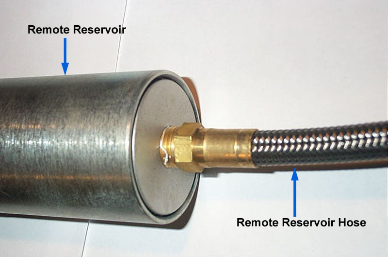 |
The remote reservoir is connected to the shock cylinder with a braided stainless steel hydraulic hose; this one is 14" long. | ||||||||||||||||||||||||||||||||||||||||||||||||||||||||||||||||||||||||||||||||||||||||||||||||||||||||||||||||||||
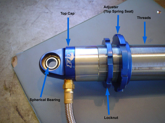 |
The top end of the shock has a spherical bearing for mounting to the chassis. The cylinder is threaded for a portion of its length, allowing adjustment of the position of the top spring seat. This adjustability of the top spring seat is a key feature of coilovers, and allows us to accommodate different length springs as well as adjust ride height, suspension height, and spring pre-load - each of which we will define and discuss in detail later. The top spring seat is also frequently know as the "adjuster." There is a locknut to lock the adjuster in position. |
||||||||||||||||||||||||||||||||||||||||||||||||||||||||||||||||||||||||||||||||||||||||||||||||||||||||||||||||||||
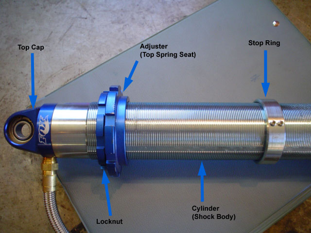 |
In addition to allowing adjustability of the top spring seat, the threaded portion of the cylinder also allows the position of the stop ring to be adjusted. The position of the stop ring is used to define the point where the dual rate slider will stop sliding. At this point in the shocks / springs travel, the spring rate transitions from the softer initial combined spring rate to the stiffer, final rate of the main spring. The point in the shocks travel where this transition occurs is called the transition point. Thus, we can say the stop ring is used to set the transition point. |
||||||||||||||||||||||||||||||||||||||||||||||||||||||||||||||||||||||||||||||||||||||||||||||||||||||||||||||||||||
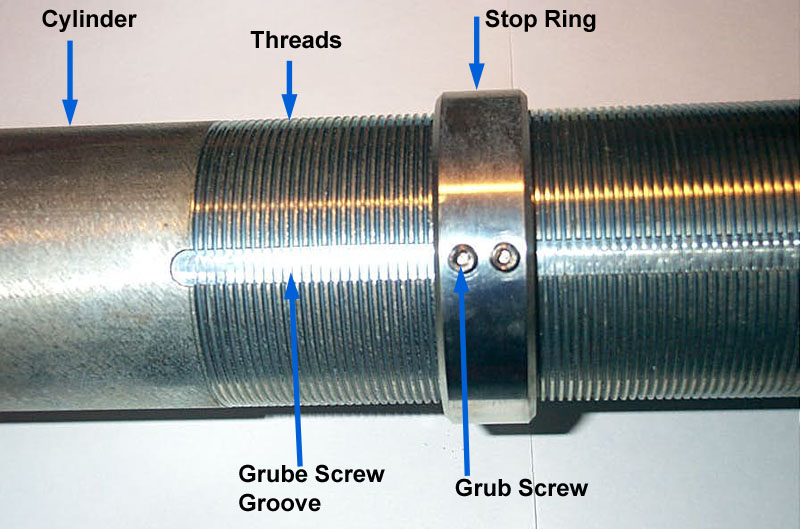 |
Once its position has been determined, on a Fox shock the stop ring is secured in position with two small Allen-head grub screws that engage a groove machined along the length of the threaded portion of the cylinder. Other shocks may use a different arrangement for the stop ring, such as two nuts that lock against one-another. |
||||||||||||||||||||||||||||||||||||||||||||||||||||||||||||||||||||||||||||||||||||||||||||||||||||||||||||||||||||
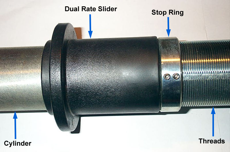 |
The dual-rate slider "floats" on the body of the shock. It is positioned between the main and tender springs. As the springs compress and rebound, the dual-rate slider slides up and down the cylinder. When the springs compress far enough, the dual-rate slider slides up until it hits the stop ring and is prevented from sliding further. At this point, the dual rate slider effectively becomes the upper spring seat, locking out the tender spring. At this point, remaining spring / shock travel occurs at the rate of main spring alone. | ||||||||||||||||||||||||||||||||||||||||||||||||||||||||||||||||||||||||||||||||||||||||||||||||||||||||||||||||||||
|
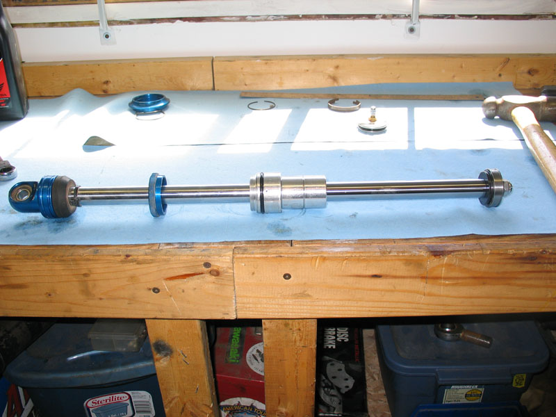
The shock body (a.k.a. the cylinder or the tube) and associated hardware. | ||||||||||||||||||||||||||||||||||||||||||||||||||||||||||||||||||||||||||||||||||||||||||||||||||||||||||||||||||||
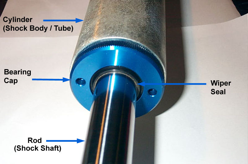 |
View of the rod, or shaft, where it enters the cylinder. The bearing cap incorporates a wiper seal to clean the shaft of contaminants as it enters the cylinder, and an internal rod guide to keep the shaft supported and aligned. |
||||||||||||||||||||||||||||||||||||||||||||||||||||||||||||||||||||||||||||||||||||||||||||||||||||||||||||||||||||
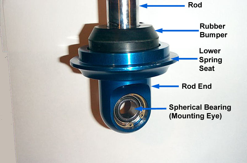 |
At the rod-end of the shock there is another spherical bearing for mounting the shock to the axle or suspension. The lower spring seat is fixed at this end. There is a small rubber bumper mounted on the shaft and resting on the lower spring seat. It is not a true bumpstop designed to handle the forces of bottoming the suspension at speed. Instead, it is merely designed to prevent damage that could otherwise occur from the lower spring seat contacting the bearing cap at full shock compression. |
||||||||||||||||||||||||||||||||||||||||||||||||||||||||||||||||||||||||||||||||||||||||||||||||||||||||||||||||||||
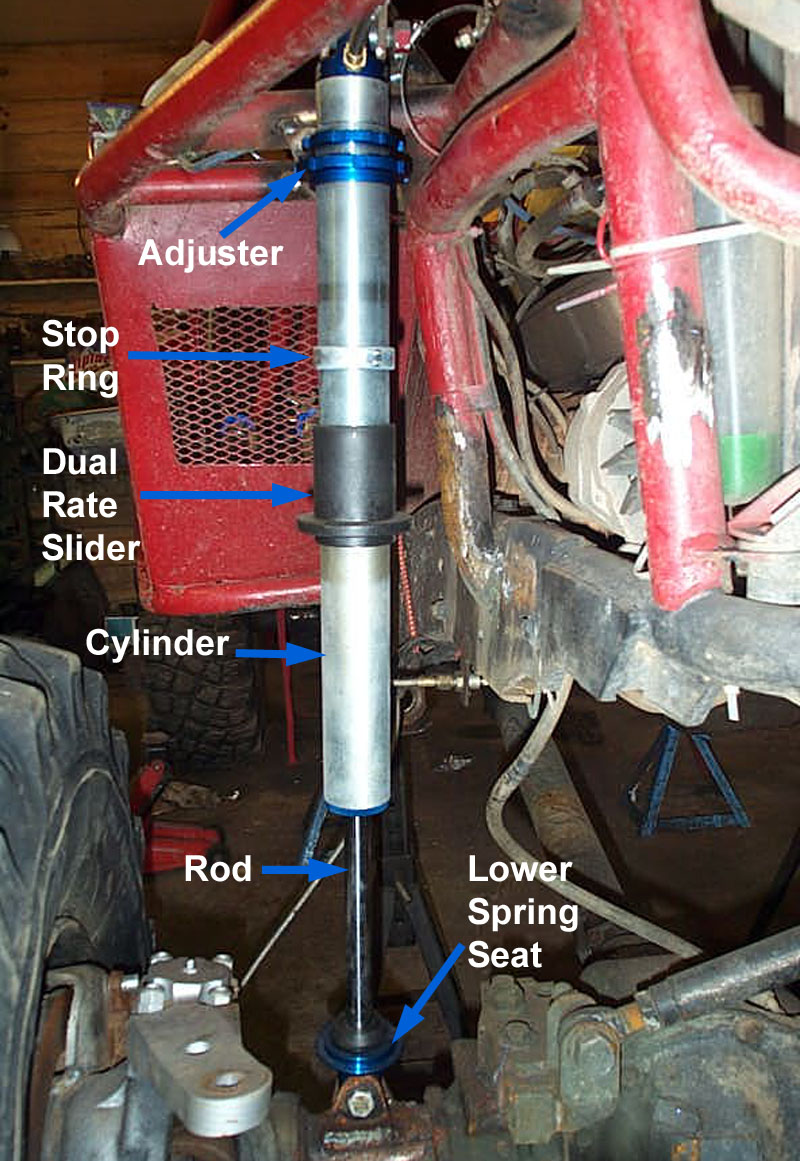 |
View of an installed shock without springs. The springs are installed on the shock between the lower spring seat and the top spring seat or "adjuster". Because the coil springs are mounted on the shock, spring travel must equal the shock travel. That is, the amount the springs change length from full bump to full droop must equal the amount the shock changes length from full bump to full droop. If the shock is setup to provide a great deal of droop, often the main and tender springs are not long enough to span the gap between the spring seats when one wheel is at full droop. The result is, the springs fall away from the top spring seat and rattle around, possibly damaging the shock. |
||||||||||||||||||||||||||||||||||||||||||||||||||||||||||||||||||||||||||||||||||||||||||||||||||||||||||||||||||||
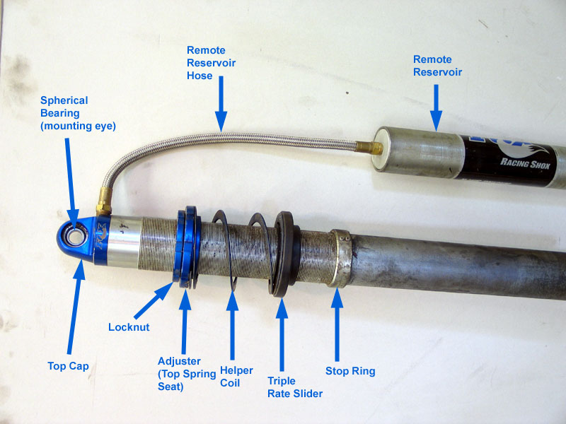 |
The solution is to install a small spring, called a "helper coil" between the top spring seat and the other springs. Another slider, called the "triple rate slider", fits between the helper coil and the tender coil. Technically, with a helper coil installed, there are now three springs installed on the shock, and the configuration is known as a "triple-rate" setup. |
||||||||||||||||||||||||||||||||||||||||||||||||||||||||||||||||||||||||||||||||||||||||||||||||||||||||||||||||||||
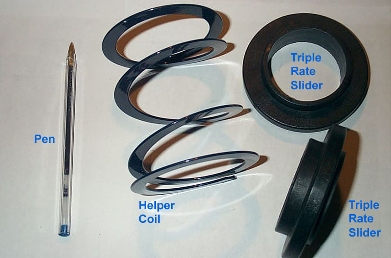 |
The helper coil is a short, flat-wound spring with very little stiffness. It can easily be compressed by hand. Resting between the top spring seat and the tender coil, it is compressed completely flat on installation. However, once the suspension nears full droop, it expands, exerting just enough force to keep the tender and main coils in place and prevent them from rattling around. Use of a helper-coil is an important consideration in selecting spring rates and lengths that we shall cover in detail later. Typically a helper coil will have a free length of 5”, a compressed height of 0.5” and a rate of only 2 lbs/in. |
||||||||||||||||||||||||||||||||||||||||||||||||||||||||||||||||||||||||||||||||||||||||||||||||||||||||||||||||||||
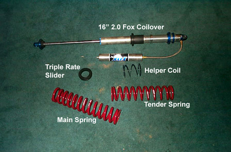 |
A complete triple-rate coilover setup. | ||||||||||||||||||||||||||||||||||||||||||||||||||||||||||||||||||||||||||||||||||||||||||||||||||||||||||||||||||||
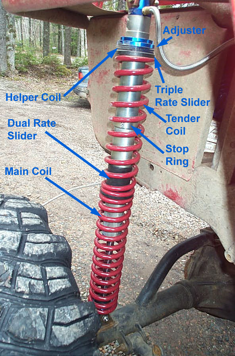 |
This picture shows a complete triple-rate coilover setup installed on the rig. Note how, at rest (called static ride height), the helper coil is compressed flat. | ||||||||||||||||||||||||||||||||||||||||||||||||||||||||||||||||||||||||||||||||||||||||||||||||||||||||||||||||||||
 |
Upper end of the installed coilover at static ride height. | ||||||||||||||||||||||||||||||||||||||||||||||||||||||||||||||||||||||||||||||||||||||||||||||||||||||||||||||||||||
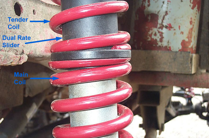 |
Installed main and tender coils separated by the dual-rate slider. | ||||||||||||||||||||||||||||||||||||||||||||||||||||||||||||||||||||||||||||||||||||||||||||||||||||||||||||||||||||
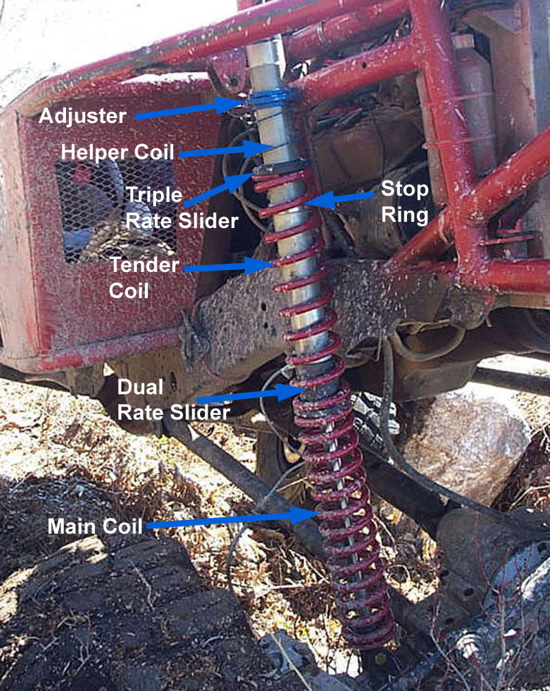 |
Installed triple-rate coilover at full droop. Note the extended helper coil between the top spring seat (adjuster) and the tender coil. Also note the triple-rate slider between the helper coil and the tender coil. Here the helper coil is exerting just enough force to keep the springs seated. |
||||||||||||||||||||||||||||||||||||||||||||||||||||||||||||||||||||||||||||||||||||||||||||||||||||||||||||||||||||
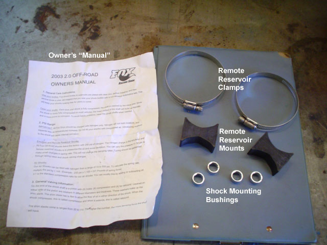 |
Additional hardware required for a coilover setup includes:
|
||||||||||||||||||||||||||||||||||||||||||||||||||||||||||||||||||||||||||||||||||||||||||||||||||||||||||||||||||||
Interim Summary:We've covered a lot of ground to this point, so let's do a brief summary before we forge on.
Great. So how do we go about getting the best performance from our coilover shocks? How do we most closely approach that magical balance between ride and handling, between firm and soft suspension? What are our goals? The Seven Goals of Suspension DesignDesigning suspension is a matter of achieving the best balance between these often competing goals:
(* by flexibility we mean the ability of the rig to apply enough force (weight) at each corner to flex / articulate the suspension enough to make use of all the wheel travel (bump) available. If springs are too stiff, wheel will stuff, then start lifting corner before full bump is reached) While avoiding
Before we design our coilover system, though, the following preliminary work must be completed. With the exception of the last point, for the purposes of this article, I shall assume these have all been completed:
With all that done, we have the information required to begin our coilover system. The first steps are:
The next step is to select some preliminary spring rates. There are many factors that go into any suspension design intended to satisfy the seven goals, including: spring rates, shock length, spring length, shock / spring mounting geometry, link geometry, shock valving, and the use of tools such as bumpstops, limit straps, and anti-roll bars. Spring rate, or how stiff the spring is, will affect all seven of the suspension design goals, so picking spring rates seems a logical place to start. This is normally what we do. But first, there is one very, very important point I wish to make, and that is:
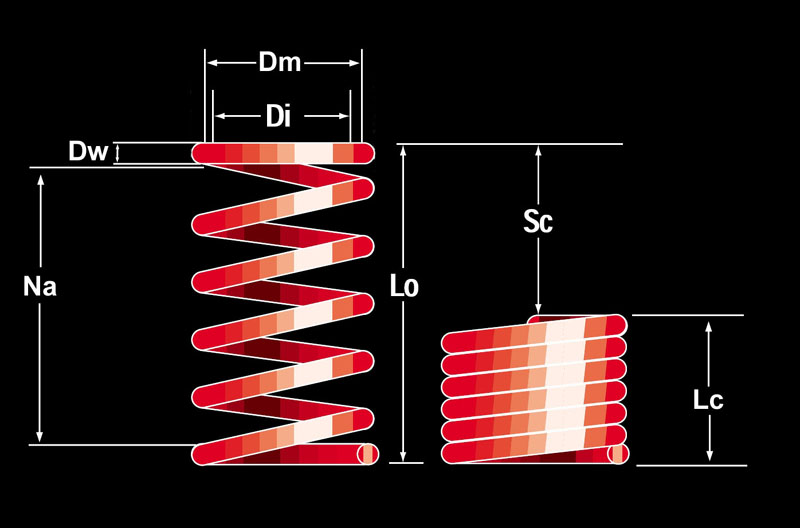
Of course, before we go about picking spring rates, we must first understand some basic spring theory. Spring TheoryA coilover spring is a compression coil spring, that is, a spring that is designed to carry a load by compressing. It will have the following properties - as illustrated in the diagram: |
|||||||||||||||||||||||||||||||||||||||||||||||||||||||||||||||||||||||||||||||||||||||||||||||||||||||||||||||||||||
 |
|
||||||||||||||||||||||||||||||||||||||||||||||||||||||||||||||||||||||||||||||||||||||||||||||||||||||||||||||||||||
Let’s examine each property in turn: Inside Diameter (Di) A spring’s diameter may be measured as the outside or inside diameter. Because coilover springs are designed to fit over a particular size of shock, we are most concerned with the inside diameter. For clearance when compressing and extending, a 2.5” ID spring goes on a 2” shock , and a 3” ID spring goes on a 2.5” shock. Wire Diameter (Dw) The spring’s wire diameter is the diameter of the wire from which the spring is wound. Coil Mean Diameter (Dm) The spring’s coil mean diameter is the diameter of the spring measured between the centres of the coils. It is equal to the inside diameter plus the wire diameter. Dm = Di + Dw Number of Active Coils (Na) The number of active coils in a spring is the number of coils that are free to compress under load. Normally this is equal to the total number of coils minus two (i.e. minus the coil at each end). This is because the coil at each end is fixed against its spring seat and therefore unable to compress. Spring Rate (k) Coil springs have a rate – a description of how stiff they are. The rate describes how much the spring will deflect (compress) for a given load (weight) placed on it. The rate is measured in pounds per inch. The greater the rate, the stiffer the spring, and the more pounds of load it takes to compress the spring one inch. Four things determine a coil spring’s rate:
Virtually any spring that is of interest to us will be made from chrome silicone steel, which has a torsional modulus of about 11,250,000 psi, so that when we calculate a spring’s rate based on its dimensions, the torsional modulus becomes a constant. The equation for calculating a spring’s rate from its dimensions is: k = 11,250,000 * (Dw)^4 / 8 * Na * (Dm)^3 By examining this equation, we see that the only dimensions affecting the spring rate of a steel coil spring are its wire diameter, coil mean diameter, and the number of active coils it has. The following table illustrates how altering these dimensions affects a spring's rate:
Since coilover springs have to have a fixed ID to fit on a given shock, the coil mean diameter for every spring for a certain shock is essentially fixed. This means, for coilover springs, the only two remaining factors that can be adjusted to create different rate springs are the wire diameter and the number of coils. For a given diameter shock, a stiffer spring will have fewer coils and / or be made from thicker wire. Conversely, a softer spring will have more coils or be made from thinner wire. Similarly, for a given rate spring, a larger diameter spring (for a larger diameter shock) will have fewer coils and / or be made from thicker wire than a spring with the same rate for a smaller diameter shock. In practical terms this results in the following rules of thumb:
That said, springs are available commercially in a huge variety of lengths, diameters, and rates. The difference between a 2.5” and 3” spring of the same rate and length is so little that it should not be used as the determining factor in deciding which size shock to buy. To measure actual spring rate, we use the equation: Spring Rate (lbs./in.) = Load (lbs) / Deflection (in.) A coil spring’s rate can either be constant or progressive. In a constant-rate spring (also called a linear spring), the spring’s rate is consistent* throughout the spring’s travel (deflection). In a progressive rate spring, the spring rate changes throughout the spring’s deflection. Progressive rate springs are easily identified as the coils will not all be wound the same diameter. We shall confine our remaining discussion to constant-rate springs, as they are the type used on coilover shocks. * Technically, even a “constant rate” spring doe not have a truly constant rate throughout its entire deflection, but in a good spring the rate will be constant for at least 80% of the spring’s travel, excluding perhaps the first and last 10%. During the first part of its travel the rate is lighter until the ends touch. During the last part of its travel the rate will increase because not all the coils bottom out at the same time - the end coils tend to bottom out first. However, since we rarely use the spring dynamically in the first or last 10% of its travel (the first 10% is consumed when we set the vehicle’s weight on the spring, and we don’t load the springs to total compression (block height) often enough to worry about the last 10% of travel) we may consider the spring to be linear or “constant rate” for our purposes. Free Length (Lo) A spring’s free length is the length it is when at rest with no load on it. Also called “free height”. Theoretically, it is only limited by when the manufacturer stops winding the wire into coils. There are practical limitations as to how long a coil spring can be made, though, depending on its diameter. Excessively long, small-diameter springs tend to buckle under load. This is the reason why most 18” long springs are only available in 3” ID and not 2.5” ID. To build a spring with a different free length while maintaining a given rate, the distance between full turns of the coil (the space between each coil of the spring) is increased or decreased to increase / decrease the free length. In this manner, all the factors that affect spring rate (coil mean diameter, wire diameter, and number of active coils) remain the same so the rate doesn't change but we get a different length spring. Properly engineered and manufactured suspension coil springs should not lose free length or installed height under normal conditions. Block Height (Lc) A spring’s block height is it’s length or height when it can be compressed no more. When a coil spring is at block height it is compressed to its maximum and all its coils will be squished up together and touching. This is referred to as “coil bind”. Block height is also known as “solid stack height”. Spring Travel (Sc) A spring’s travel, or maximum possible deflection, is the difference between it’s free length and its block height. Also known as maximum displacement. Force Limit (Fc) A coil spring’s force limit is the force (or load or weight) on it when it is at block height. It is the maximum load the spring can withstand without damage. It is also the load that must be applied to fully compress the spring – i.e. to use all of its travel. This is important to us for two reasons – it tells us how much load we can place on the spring, but just as importantly it tells us the load we must place on the spring to use all of its travel. This is particularly important in designing long-travel suspension where we are trying to make the most of all the spring travel we have to match the amount of wheel travel we have from using long-travel shocks and linked suspensions. Dual-Rate SpringsAs we've discussed, suspension design is a precise balancing act. On one hand, the spring system should be soft enough to allow required flex for rock crawling and to compensate for road and trail irregularities, assuring maximum traction and providing a comfortable ride. On the on the other hand the spring system must be firm enough to control the wheels over big and fast bumps, and provide adequate resistance to roll, squat, and dive during climbing, descending, side-hilling, cornering, acceleration, and braking. An advantage to coilover suspension is that this perfect balance can be more closely approached by using a dual-rate system. By selecting two springs from amongst hundreds of individually available springs and combining them in series, a huge number of possible initial and final spring rates is achievable. The position of the stop-ring is set to stop the travel of the DRS before the tender spring binds, reducing wear on the tender spring, but, more importantly, allowing the user to tune where in the vehicle’s wheel travel the transition from soft initial rate to firm final rate occurs. In general the stop ring is located so that the final rate comes into effect in the last 20% to 40% of the shocks compression travel. This way the suspension will have a higher wheel rate for the last 20% to 40% of total travel before the shock bottoms out. The initial spring rate of a dual-rate system is calculated as the product of the individual spring rates divided by the sum of the individual spring rates, according to the following formula: Ki = (Km * Kt) / (Km + Kt) Where: Ki = Initial Spring Rate (of combined springs) The final spring rate (effective after the tender spring binds or the DRS has hit the stop) is simply the rate of the main spring. Kf = Km
Now that we have a good understanding of spring theory, we are almost ready to move on to selecting spring rates. But before we do, we must first cover a a few more key definitions and explore the concepts of leverage and the "installation ratio".
As we've just discussed, there is an important relationship between shock travel and wheel travel, known as the installation ratio, that depends on the position relative to the wheel and the angle at which the shock is installed. Because the springs are co-located with the shock in a coilover, this ratio is also important in understanding the difference between the force at the wheel and the force on the spring, and by extension, the spring rate at the wheel and the actual rate of the spring as manufactured. In other words, how, where, and at what angle we install the coilover shock with its installed springs causes there to be a difference between shock travel and wheel travel, spring force and wheel force, and spring rate and wheel rate (wheel rate being the effective spring rate "seen" or "felt at the wheel. This is a very important consideration for us because it is the wheel travel, wheel force, and wheel rate that actually define the characteristics of the suspension and how it will perform. We really don't give a darn about the actual values of shock travel and spring rate (i.e. what's printed on the side of the components), except in that they contribute to the wheel travel and wheel rate. For example, if someone says "I have 12 inch shocks and a spring rate of 250 lbs/in" that tells us exactly nothing about their suspension and how it might perform. On the other hand, if someone were to say "I have 18 inches of wheel travel, an initial wheel rate of 100 lbs/in and a final wheel rate of 275 lbs/in" now that would tell us something. But we're getting ahead of ourselves. In order to be able to understand (and design with, or compensate for) the differences, we must understand where they come from. The answer is "leverage between wheel and shock / spring." and so to fully understand let's first review some basic leverage theory. I must make clear one very important point, before we begin: In the following discussion we shall be talking about ratios, dimensions, and angles. Obviously, a rig's suspension is a dynamic, moving thing. But dynamic, moving things are horribly complicated things to measure and analyze - especially if you're just starting out. So to begin with, we pick some given fixed static point at which to take our measurements and make our calculations. Normally, and in this article, we use static ride height. This is perfectly adequate for initial design purposes and perfectly adequate for the purposes of measuring the dimensions the BillaVista spring rate calculator (BV Calculator) requires as inputs. But, for the sake of complete technical accuracy - I would be remiss if I didn't point out that in a real working dynamic moving suspension, dimensions and angles and such can, and do, change - changing the results of any calculations on a pretty-much continuous basis. Similarly, in the following discussion, when we speak of wheel travel, we are talking about ride-travel (both wheels moving up and down together) as opposed to roll travel. With roll travel, there are a whole 'nuther set of variables and angles to consider, which would make things entirely too confusing at first. And again, for our purposes at this stage, ride travel is a perfectly adequate, clear, and simple model to use - so we do. Later in the series we will get into roll travel and it's attendant difficulties. But for now, back to the basics. Leverage TheoryLeverage is an important concept for us to understand because quite often the wheel will exert some leverage on the shock and spring, which we must account for in our calculations and design. If we could mount the spring on the vehicle at the centre of the wheel hub, perfectly vertical, and the suspension only ever travelled perfectly vertically, we wouldn't have to worry about the effect of leverage and angles in the suspension. Clearly this is impossible, and so we must be concerned with leverage. The leverage affects displacement (travel), force (load), and rate. The leverage means that wheel travel will be different from spring or shock travel, that wheel rate will be different from spring rate, and that the force felt at the wheel will be different from the force on the spring. Clearly, important stuff. But let's not get ahead of ourselves. We'll begin by exploring the affect of leverage on displacement. That is, we're going to discover why it is that wheel travel differs from shock travel because of the effect of leverage. In other words, why the position and angle at which the shock is installed means there is a difference between wheel travel and shock travel. Work is force times distance. W = F x d. By looking at the equation we can see that if work remains constant, increasing force decreases distance or increasing distance decreases force. A lever is a simple machine that trades force for distance or vice versa. We all use levers every single day. The simplest example is a door. Imagine you open a door by pushing near the hinges. Now imagine you open the same door by pushing near the handle. In either case the same amount of work is done. But, when you push near the hinges you must push harder (force is greater) but over a smaller distance (distance is less). When you push near the handle less force is required, but you must push for a greater distance. The door is a lever that trades distance for force - putting the handle on the opposite side of the door from the hinges makes it easier to open. Normally this is how we think of using a lever - to make things easier. For example, a lever makes it possible to lift a heavy object with low input force, but requires us to apply the input force for a greater distance than the object will be lifted. Nothing in life is free - the lever costs us distance and pays us back in force. Let's look at the parts of a lever and how it works.
Summary of lever types:
Bottom line: a lever trades force for distance in equal but inverse ratios. If we know one ratio, we know the other. Depending on shock mounting geometry, if there is a lever created between wheel (effort) and shock (load), then the displacement of the wheel (wheel travel) will differ from the displacement of the shock (shock travel). The Angle FactorJust as leverage between wheel and shock (created by where we mount the shock) can create a difference between wheel travel and shock travel, so to does the angle at which we mount the shock. That is, the angle at which me mount the shock creates a difference between wheel travel and shock travel. |
|||||||||||||||||||||||||||||||||||||||||||||||||||||||||||||||||||||||||||||||||||||||||||||||||||||||||||||||||||||
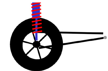 |
If we mounted the shock vertically, (at an angle of 0° from vertical) then there would be no difference between shock travel and wheel travel. For every inch the wheel goes up, the shock compresses one inch. |
||||||||||||||||||||||||||||||||||||||||||||||||||||||||||||||||||||||||||||||||||||||||||||||||||||||||||||||||||||
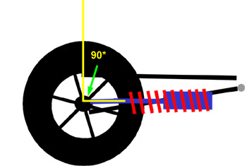 |
Using a ludicrously extreme example for illustrative purposes: if we mounted the shock laying flat (at an angle of 90° to vertical) then shock travel would equal 0, regardless of wheel travel. In this configuration, no matter how much the wheel travels vertically, the shock would just pivot on its mountings, but wouldn't compress at all. Although this example is completely impractical, it demonstrates that as the angle increases the shock travel decreases compared to wheel travel. |
||||||||||||||||||||||||||||||||||||||||||||||||||||||||||||||||||||||||||||||||||||||||||||||||||||||||||||||||||||
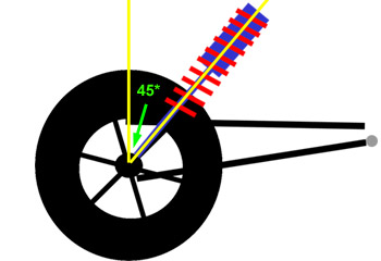 |
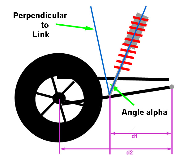
If we mount the shock at 45° from vertical, the relationship between shock travel and wheel travel is not so immediately apparent, although we know it depends on the angle, and we know the shock travel will be something less than the wheel travel. But by how much? Wouldn't it be great if there was a ratio that related shock travel to wheel travel in terms of the angle? Well, there is. I'll save you the trigonometric derivation, but it turns out that the shock travel depends on the cosine of the angle between the shock and vertical. We call the angle 'alpha'. That is, the ratio that describes the relationship between shock travel and wheel travel is cos(alpha). We call this ratio the "angle correction factor" or ACF. ACF = cos(alpha) |
||||||||||||||||||||||||||||||||||||||||||||||||||||||||||||||||||||||||||||||||||||||||||||||||||||||||||||||||||||
| That's it. We now understand the two factors that describe the relationship between wheel travel and shock travel in terms of the mounting position and angle of the shock.
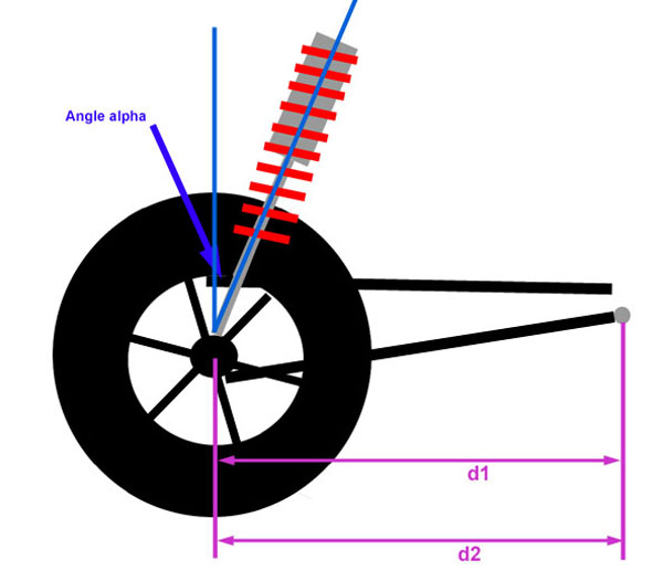
Mounting position of the shock creates leverage. Leverage modifies the shock travel compared to the wheel travel by the displacement ratio (DR). You may see the displacement ratio referred to in some circles as the "motion ratio" or MR. Mounting angle of the shock modifies the shock travel compared to the wheel travel by the ratio we call angle correction factor (ACF). DR = d1/d2 ACF = cos(alpha) For simplicity and elegance, we combine both of these factors into a single factor, or ratio, that describes the relationship between wheel travel and shock travel for any position or angle at which the shock / spring is mounted. We call it the installation ratio, or IR. IR = DR * ACF For conciseness I shall forthwith refer to the "position and angle at which the shock / spring is mounted" as simply the "shock geometry". Installation RatioSo the installation ratio is a dimensionless ratio that relates wheel travel to shock / spring travel, as follows: shock travel is equal to wheel travel multiplied by the installation ratio; or ST = WT * IR, and therefore, WT = ST / IR, and IR = ST / WT and since IR = DR * ACF; and DR = d1/d2; and ACF = cos(alpha) All we need to know are the dimensions d1 & d2 and the angle alpha and we can calculate shock travel from wheel travel or wheel travel from shock travel; for the particular shock geometry. Since IR is a ratio of displacement, or travel, the most obvious uses then would be:
The IR's usefulness doesn't end there though. Just as there is a difference between between wheel travel and spring travel due to leverage and angle, so there is also a difference between the actual spring rate of the installed coil, and the spring rate experienced at the wheel due to this leverage and angle. This "effective" spring rate at the wheel is called the wheel rate (WR). Most people like to quote and compare spring rates. Stopping them from doing this is one of the most important objectives I had in mind when starting this project. I want to get people to stop asking, "What spring rate are you running?" and start asking, "What wheel rate are you running?". Why? Because essentially, spring rate alone is completely meaningless without knowing how the spring / shock are installed. Now, we could say, "What's your spring rate and where is the shock located, and at what angle, and what are your d1 & d2 dimensions?", but that would be painful. Instead, we have the term "wheel rate" which takes all that into account - it describes the effective spring rate at the wheel by taking into account the shock / spring's installation. Before we look at exactly how it does that, we should understand that it is the wheel rate, and not the spring rate that:
So what is the relationship between wheel rate and spring rate and what does the difference between wheel travel and shock travel (the installation ratio) have to do with it? Recall that the wheel acts on the spring through a lever and a lever trades force for displacement in equal but inverse ratios. The lever created between wheel and shock / spring trades wheel travel for wheel force (or vice versa, depending on the class of lever the suspension geometry matches) - just like a simple lever. If we know one ratio, we know the other. In other words, if we know the ratio by which wheel travel and shock / spring travel differ, we also know the ratio by which wheel force and spring force differ. And of course we know this ratio - it is the installation ratio. We can measure the d1, d2, and alpha of our spring installation (an example of how will follow shortly) and calculate IR from IR = DR * ACF = (d1/d2) * cos(alpha) Now, remember what we were originally after was the difference between the wheel rate and the spring rate. Well, since rate = force / distance, and we know by how much the distance differs (the IR), we also know how much the force differs - it's the same ratio. So, to calculate wheel rate from spring rate - if we know the original spring rate (and we ought to as we bought the springs!) and we know the force ratio and the distance ratio we can calculate the wheel rate. And of course we know the ratios - they're the same, namely, the installation ratio. Since the ratio affects both force and distance (remember the lever example) we must apply it to the spring rate twice to get the wheel rate. The equation is: WR = k * IR * IR where: WR = wheel rate (lbs/in) K = spring rate (lbs/in); and IR = installation ratio. SummaryIn summary, because of the way a lever works, the difference in travel tells us all we kneed to know to calculate the difference in rate between the spring and the wheel.
The following says the same thing algebraically, for the mathematically inclined:
The Big FiveAll this theory simply uses the laws of leverage (force and displacement ratios) to relate six things:
and combining these two
These relationships can be boiled down to what we call the "big five" equations. These equations are the base, root equations for almost all spring / suspension work. They are the equations boiled down to their most basic form - from which all other equations can be derived. The "big five" and their descriptions are:
Let's summarize our new terms and then proceed to a concrete example.
Measuring d1, d2, & alpha - Practical Calculation of the IRThe BillaVista spring rate calculator (BV Calculator) requires the installation ratio in order to calculate the recommended preliminary spring rates required to arrive at a target wheel rate. It is designed to calculate the IR from the following user inputs: d1, d2, and alpha. The following practical examples should solidify our understanding of the IR and illustrate how to measure the required dimensions for a common 4-link rear suspension. However, if you understand the theory, you can figure out and measure d1, d2, and alpha for any style suspension. As a side note - all suspensions will have an IR, but it may be that the IR is 1. Before we continue, I must re-emphasize that all of our discussions to this point regarding DR's, ACF's, and IR's have been with regards to some fixed static point in the suspension's travel - namely static ride height. Things begin to change, and get exponentially more complicated, when we attempt to analyze a rig's suspension as a dynamic, moving thing. So to begin with, we take our measurements and make our calculations. at static ride height. This is perfectly adequate for initial design purposes and perfectly adequate for the purposes of measuring the dimensions the BV Calculator requires as inputs. But, for the sake of complete technical accuracy - I would be remiss if I didn't point out that in a real working dynamic moving suspension, dimensions and angles and such can, and do, change - changing the results of any calculations on a pretty-much continuous basis. Just keep in mind that, for now, we're sticking to the basics - measurements and calculations at static ride height and wheel travel modelled as ride travel. |
|||||||||||||||||||||||||||||||||||||||||||||||||||||||||||||||||||||||||||||||||||||||||||||||||||||||||||||||||||||
 Side View |
Example 1: 4-link rear, shock mounted on axle. In "lever" terms we have: Setup:second class lever since d1 = d2, DR = d1/d2 = 1 In other words, the wheel has no lever through which it applies force to the springs. This situation is shown at left. The angle alpha is measured with an angle finder, and is the angle from vertical at which the shock is mounted. The ACF = cosine(alpha). If alpha = 20° IR = DR * ACF In other words, for every inch of wheel travel, the shock will travel 0.94" WR = k * (0.94)^2 In other words, the wheel rate will be 88% of the spring rate. The BV Calculator will make the calculations, the user simply needs to enter values for d1, d2, and alpha. Strictly speaking, because d1 = d2, any value can be entered for d1 and d2 as long as it's the same for both. |
||||||||||||||||||||||||||||||||||||||||||||||||||||||||||||||||||||||||||||||||||||||||||||||||||||||||||||||||||||
 Side View |
Example 2: 4-link rear, shock mounted on lower link. In "lever" terms we have: Setup:second class lever DR = d1/d2 In other words, if the coilover is mounted on the lower link (control arm), there will be a displacement ratio, as shown at left. Since the DR is a dimensionless ratio, d1 and d2 can actually be measured in any plane and at any angle, as long as you are consistent with both measurements. i.e. if you measure d2 parallel to the ground, be sure to measure d1 also parallel to the ground. Conversely, you could also measure both dimensions parallel with the link. Because of the shock mounting location on the link, the angle alpha is not measured between the shock axis and vertical, but instead between the shock axis and a line perpendicular to the link, as shown at left. This accounts for angle between the link and the ground. Obviously, if the link is parallel to the ground, the line perpendicular will be vertical. The ACF = cosine(alpha). If alpha = 20°, d2 = 48", and d1=36" DR = d1/d2 = 36 / 48 = 0.75 ACF = Cos(20°) = 0.94 IR = DR * ACF In other words, for every inch of wheel travel, the shock will travel 0.7" You will notice many desert race truck setup similar to this, which is how they achieve 30+ inches of wheel travel, even though no 30" shocks exist. WR = k * IR^2 In other words, the wheel rate will only be 50% of the spring rate. |
||||||||||||||||||||||||||||||||||||||||||||||||||||||||||||||||||||||||||||||||||||||||||||||||||||||||||||||||||||
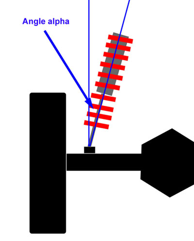 Front or Rear View |
Compound values of alpha: The angle alpha will normally be because the shock leans towards the centre of the vehicle, when viewed from the side, as in the above two diagrams; OR as shown in this diagram, it may be because the shock leans towards the centreline of the vehicle when viewed from the front or rear. Of course, the shock may be installed leaning in both directions - in which case the angle alpha will be a combination of both angles, and is best measured with an angle finder. If, however, for planning purposes, you wish to calculate the combined angle produced when you lean the shock sideways some angle x and lean it forward some angle z, you would do so as follows: alpha = arccos((cos(x) * cos(z))) E.g. If I lean the shock sideways 20° and forwards 30°, the resultant angle from vertical is arccos((cos(20) * cos(30))) = 35.5° |
||||||||||||||||||||||||||||||||||||||||||||||||||||||||||||||||||||||||||||||||||||||||||||||||||||||||||||||||||||
There is, of course, one other way to calculate IR, and that is by direct measurement. Suppose we have the shock already installed on the rig, since: ST = WT * IR, then IR = ST / WT In other words, the IR is the shock travel, divided by the wheel travel. If we therefore take several measurements of WT and ST we can calculate an average value for IR, using a procedure called a "linear fit"..
In the example above, we have: slope = rise / run Therefore, the slope of the line is 0.775 and the IR is 0.775. In other words, for every inch of wheel travel, the shock travels approximately 0.775" Measuring CSWThe last thing we must accurately measure before using the BV Calculator is the corner sprung weight at each corner of the vehicle. There are a number of different ways to measure corner sprung weight. If you have access to a small portable scale of appropriate capacity (like a race car scale) you can place it under the tire and measure the corner weight of the rig. Be sure to block up the other 3 tires the same height as the scale though, otherwise your result will be inaccurate due to weight transfer. Then, leaving the tire on the scale, use a Hi-Lift jack to jack up that end of the rig until the suspension goes slack and the sprung weight is not on the suspension. Read the scale again and record the value of the unsprung weight. Subtracting the unsprung weight from the total weight will give you the sprung weight at that corner. If you don't have a portable scale, you may be able to do the same thing at a truck scale, but the difficulty will be taking the sprung weight off the suspension in order to measure the unsprung weight. If you have access to neither, you can attempt to rig up a system using a bathroom scale, like this: |
|||||||||||||||||||||||||||||||||||||||||||||||||||||||||||||||||||||||||||||||||||||||||||||||||||||||||||||||||||||
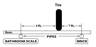 |
Good Lord it's an upside down second class lever! See, I told you physics and math were useful! Recall: mechanical advantage = effort arm / load arm. In this case the effort arm is y and the load arm is x+y. Therefore, the weight the scale will see is the weight on the tire, multiplied by y/y+x. You can vary x and y to avoid exceeding the capacity of the scale. For example, if x = 3 ft. and y = 1 ft., the scale will see 1/4 of the weight on the tire. Be aware that the beam will have to be very strong and rigid. It's a little hokey, but may be better than simply guessing. |
||||||||||||||||||||||||||||||||||||||||||||||||||||||||||||||||||||||||||||||||||||||||||||||||||||||||||||||||||||
The easiest way to explain finding CSW is this. Measure the deflection of the spring and find the force on the spring using the definition of spring rate Force on the spring = spring deflection * spring rate You know your spring's rate, you measure deflection so you multiply the two and have the force on the spring. Now you use the definition of IR in terms of what it means to force. So find force on spring ---> Fs = ks * ds Find that force at the wheel ---> Fw = Fs * IR Fw is corner sprung weight. We've already explained all that, so no need to introduce anything new, just apply what we know. Make sense? If you already have coil springs installed, you can calculate the CSW by measuring the deflection of the springs at ride height and multiplying this by the spring's rate and the IR at that corner. If you don't know the spring rate, you calculate it by measuring the coil's dimensions and using the formula and definitions given in the previous section on spring theory. (i.e. k = 11,250,000 * (Dw)^4 / 8 * Na * (Dm)^3). The reason you have to multiply the spring rate by the IR is because of the effect of suspension leverage on force. We can prove this to ourselves algebraically, because the corner sprung weight is actually just the force at the wheel:
The BV Calculator has a sheet to perform the calculations for you if you enter the appropriate variables (d1, d2, alpha, spring rate, the free length of the spring, and the installed length of the spring). In practice I have found that the results vary a little, depending on if you measure the deflection of tender, main, or combined spring stack - probably due to limitations on accurately measuring the spring's length at ride height. As such, the calculator will also produce an average if you have values for more than one spring to enter. Suspension FrequencyWhat is suspension frequency?Traditionally, rockcrawlers and trail riders have thought of suspension chiefly in terms of suspension height - the amount of droop travel and bump travel the suspension provides. And traditionally we have designed our suspension with suspension height as the foremost goal. There is, however, another core property of any suspension, a property that is essential in defining low speed performance and that becomes increasingly important as speeds increase. The property is suspension frequency (Fn). Recall from our very early discussion of suspension; we said that "when a vehicle's wheel hits a bump, the rate at which the (undamped) springs compress and rebound is called the suspension frequency". If you were to remove the shocks from a car and then push down and release a corner, that corner would bounce up and down, or oscillate, at the suspension's natural frequency. If you did it to a luxury car with soft springs, like a Cadillac, the car would bounce up and down fairly slowly - the suspension frequency would be comparatively low. If, on the other hand, you did it to a stiffly sprung sports car, the car would bounce up and down more quickly - the suspension frequency would be higher. We also know that the softly sprung luxury car provides a comfortable ride and soaks up small bumps and potholes well, but that it is prone to excessive body roll when cornering, acceleration squat, and brake dive. Conversely, the stiffly sprung sports car exhibits excellent handling, but can provide a stiff, jarring ride. So intuitively we already know that the suspension frequency is an indicator of both ride quality and handling. This is one of the characteristics that makes it so useful in suspension design. Suspension frequency is as important in describing an off-road rig's performance as it is in describing a car's ride and handling. A rig with a low frequency suspension will be flexible and comfortable, but may lack roll resistance and the ability to soak up large bumps and potholes at speed without bottoming. A rig with a higher frequency suspension may be able to blast through the whoops, but at what cost to ride quality, and will it be flexible enough to use all it's wheel travel when crawling through a field of boulders? As with anything, the "right" frequency is a matter of balance. The front to rear balance of a rig's suspension frequency is also extremely important in defining how the rig will perform - especially in the faster rough stuff. If you have ever seen a rig bucking back and forth from front to rear axle while crossing rough terrain at speed, you have seen an example of poor front to rear suspension frequency balance. Suspension frequency also gets exponentially more important the faster we go. This is becoming increasingly significant as rock sports like rock racing, rock cross, and King of the Hammers type events grow in popularity and begin to blur the line between traditional rockcrawling and off-road desert racing. In traditional rockcrawling, suspension performance is typically slow and quasi-static as the rig crawls. When crawling slowly over a boulder the wheel reacts slowly - in technical terms the wheel is excited at a slow velocity. Think of our car corner pushing again, and push down and release very slowly - nothing terribly exciting happens, and because we do it slowly, the differences between the Caddy and the coupé aren't terribly noticeable or important. However, when you hit a bump / dip / log at speed or land from a jump at speed you excite the wheels at a high velocity. The reaction of the suspension and wheels, and consequently vehicle handling, following high velocity excitation is very dependent on the natural frequency of the suspension. Back to our car corner pushing experiment - imagine that when you push down and and release the corner, you do it quickly and repeatedly. Now the difference between the two is readily apparent. The Caddy will dip and sway and wallow, the sports car will bounce and jiggle quickly. This is the suspension frequency at work. The ability to soak up bumps at speed depends heavily on suspension frequency - certain frequencies will help keep the vehicle stable as its front hits a bump and a split-second later the rear hits the same bump. Research, development, and testing develop ranges for suspension frequencies, front and rear, that work well for particular rigs in particular terrain. For now, we should be convinced that suspension frequency is an important property in suspension design. You may be thinking to yourself, "Yea, but you said the suspension frequency was the undamped rate of oscillation, and we know the shocks provide damping - that's what they're designed to do". And you'd be right, the shocks do have a big effect on the suspension's performance - BUT it is critical to get the springs and therefore the suspension frequency right first - otherwise the shocks will end up"fighting" the springs and any attempt at valving the shocks will be a frustrating exercise in futility. Let me put it this way - if the spring rates and suspension frequency are wrong and you attempt to dial in the shock valving it would be like trying to set ignition timing when the valve timing is off! I know I began the article by stating that there are very few hard and fast "rules" in suspension design. This may be the exception. If you don't get the suspension frequency right, you will never get the ultimate performance you seek. In fact, I would argue that it is so important, it is THE goal in suspension design. By thinking and designing in terms of suspension frequency we don’t have to know the sprung weight or wheel rate to compare the suspensions of different vehicles, be they luxury cars, f1 racing cars, rock crawlers or loaded 30 ton trucks, as the suspension frequency takes these factors into account. Seldom will you see suspension height or "amount of droop available" referred to in circles outside the rock-crawling world but suspension frequencies are frequently discussed in all arenas of suspension design. Learning to think and calculate in terms of frequency can open up to us a whole world of valuable data and experience - experience from which we can draw valuable design insight. Unlike suspension height, suspension frequency includes an intuitive assessment of ride comfort and handling. If I say “I have 6 inches of droop” it is hard to visualize or imagine the overall ride and handling – is that soft or stiff? On the other hand – if we say a flexy competition rock buggy has a suspension frequency of perhaps 0.85 to 1.0 Hz, a luxury car has a suspension frequency of 1.0 to 1.3 Hz, a sports car 1.3 to 1.7 Hz, and a Formula 1 racing car 2.7 to 3.3 Hz , we can intuitively relate frequency to ride and handling. In fact, by using frequency we can even relate to non-automotive information - for example, the frequency of a person walking normally is usually about 2.0 Hz and a boat gently rising and falling with long swells may have a frequency as low as 0.5 Hz or less. The lower the frequency the softer the ride feels, the more flexy the suspension will be, but the less effective it will be at keeping the wheels in contact with the ground at higher speeds, and the less capable it will be of soaking up bumps at speed with bottoming or serious wallowing that can lead to a loss of traction and / or control. As suspension frequency increases the suspension becomes more stiff and responsive, more capable of handling the impact of bumps at speed and jumps, but the less flexible it will be for boulder crawling and the harsher the ride will be. There's a point between the extremes of low and high frequency that strikes the best balance for any given vehicle and its intended use. Just as importantly, by studying the suspension frequencies of different vehicles with known performance characteristics we can now intuitively understand what we may achieve by designing our rig for a particular suspension frequency. By quoting suspension frequency we can describe and compare suspensions across different vehicles, without having to know sprung weight or spring rate. If my 1-ton trail buggy has a suspension frequency of 1.1 Hz, and so does my buddy's pro lightweight moon buggy, we know that they will have similar performance characteristics and will feel similar in ride quality - even though they have dramatically different weights, spring rates, spring lengths, etc. Of course, despite its many virtues, suspension frequency alone is not the beginning and the end of suspension design - not least of all because it is the undamped natural frequency and the use of shocks, variable or adaptive valving, and other components like anti-roll bars and rising rate bumpstops create the complete suspension system that, as a whole, dictates the vehicle's ride and handling. Still more factors, such as unsprung weight, also play a part in ride and handling, particularly as speeds increase. Suspension frequency is just one part of the equation - but it happens to be the most important, and in my opinion, the best basis on which to select preliminary spring rates. In short, rockcrawlers, trail riders, and rock racers need to begin to think and design in terms of suspension frequency, to build up a body of experience of what frequencies work well for different types of rigs and terrains, so that we can then easily select spring rates to achieve wheel rates to achieve the desired suspension frequency. How do we calculate suspension frequency?Before we describe the calculation of a vehicle's suspension frequency, it is helpful to explore the calculation of natural frequency using a simplified model or system. We shall use a simple spring and mass system, as pictured below. |
|||||||||||||||||||||||||||||||||||||||||||||||||||||||||||||||||||||||||||||||||||||||||||||||||||||||||||||||||||||
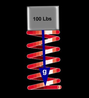 |
The natural frequency of any system is given by the equation: Fn = (sqrt(k/m)) / 2pi where; Fn = natural frequency in Hz |
||||||||||||||||||||||||||||||||||||||||||||||||||||||||||||||||||||||||||||||||||||||||||||||||||||||||||||||||||||
Since we are not used to working with mass, if we re-write the equation so that we can use weight instead, we get: Fn = sqrt ((386.088*k) / W ) / 2pi If, for a moment, we strip away some of the math and get rid of the constants (the sqrt, the 386.088, and the 2pi) we are left with: Fn "depends on" k / w The natural frequency "depends on" the spring rate divided by the weight. In other words, if we increase the spring rate (use a stiffer spring), or decrease the weight (on the spring), the frequency will go up. This confirms the intuitive conclusions about natural frequency that we were able to draw from our simple experiment of bouncing the corners of the luxury and sports car. In other words, two systems can have equal frequencies, even if one has a stiff spring with a large weight on it, and the other a soft spring but with a smaller weight on it. A note of caution here. Because it is more convenient and logical for us, we have substituted weight for mass in the equation. However, this comes at a price. Because weight is a force, and F = m * a, in order to use weight in place of mass, we must divide it by the acceleration due to gravity. Since this acceleration always occurs in a vertical direction, for the equation to be accurate, the weight and spring must be oriented vertically, as illustrated in our simple model above. What happens when we substitute a real-world suspension, where we know the spring is quite often not vertical, for the simple model? Can we still use the equation to calculate the frequency of a suspension system? We can indeed apply the equation to a suspension system by using the wheel rate instead of the spring rate. |
|||||||||||||||||||||||||||||||||||||||||||||||||||||||||||||||||||||||||||||||||||||||||||||||||||||||||||||||||||||
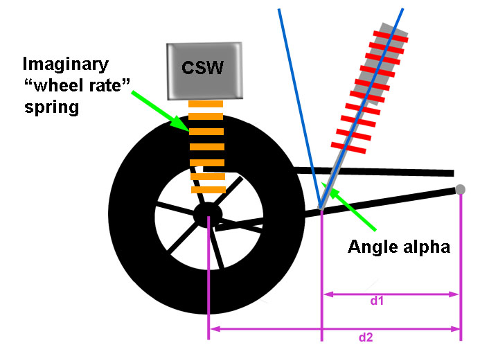 |
By calculating a wheel rate using the installation ratio, we effectively create an "imaginary spring" between the wheel and chassis. This imaginary spring, the "wheel rate spring" is oriented vertically, and the weight it carries is the corner sprung weight of the rig. Therefore, we can calculate the Fn of our actual suspension using the wheel rate and the corner sprung weight. By substituting into the equation for Fn, we arrive at: Fn = sqrt ((386.088 * WR ) / CSW ) / 2pi |
||||||||||||||||||||||||||||||||||||||||||||||||||||||||||||||||||||||||||||||||||||||||||||||||||||||||||||||||||||
So we can calculate the Fn of our suspension if we know the wheel rate and the corner sprung weight. Working in the other direction then, we can easily select a target suspension frequency, and work the equations backwards to calculate, for our given CSW, the wheel rate we need to get our selected Fn. Of course, we can similarly continue to work the equations backwards and determine the combination of spring rate (k) and shock geometry (IR) we need to get that wheel rate. And that is just what we're going to do! That is, we are going to select preliminary spring rates that, combined with our shock / spring geometry, will achieve a certain wheel rate that, combined with our corner sprung weight, will give us our target suspension frequency. Fortunately, the BV Calculator will do all the math for you, all you need is a tape measure, an angle finder, and an accurate corner sprung weight. Fn can be calculated for any individual corner or the front or rear suspension. To calculate Fn for a corner, use the corner sprung weight and the wheel rate at that corner. To calculate for the front or rear you would use the sum of the corner sprung weights at that end and the additive wheel rate of both wheels on that axle. If weight is distributed evenly side to side, and the wheel rates are the same for both wheels of a given axle, the frequency of the suspension at that end will match the Fn of the corners. Equal suspension frequencies at both corners of the front or rear is a highly desirable state. It is easy to achieve if weights are evenly distributed side to side - but this is often not the case. Consider the case of a lightweight moonbuggy with a heavy driver sitting to one side (Bigelow, are you reading this? ;-) The beauty of designing suspension in terms of frequency is that, as we have just learned, we can alter the wheel rates at each corner to compensate for the different weights at each corner to achieve equal suspension frequencies at each corner of an end, and thus a balanced suspension side to side(or even front to rear if so desired) - even though weight distribution is not equal. The Relationship Between Fn and SH"But what about suspension height?", you may be asking. Because the wheel rate (spring rate and IR) affects both suspension frequency and suspension height, there is obviously a relationship between Fn and SH. That is, the spring rate we select (for a given sprung weight and shock geometry), will determine not only the suspension frequency, but also have an effect on the suspension height. The spring rate affects suspension height because setting the corner sprung weight on the springs causes them to deflect a certain amount and the shock compresses an equal amount because the springs are installed on the shock. This shock compression due to the weight on the springs contributes to how much droop travel will be available. It is not, however, the only factor that does - which is why Fn and SH are related but not equivalent. Recall that the amount of droop travel available, aka the suspension height, is some portion of the total wheel travel (obviously the portion where the wheel goes down, or droops, from static ride height). Recall also, that wheel travel and shock travel are related by the installation ratio - the installation ratio is the ratio of wheel travel to shock travel, or IR = ST / WT We can rearrange this equation to read: WT = ST / IR That means that, for a given shock geometry wheel travel available is controlled by the shock travel (assuming bumpstops and limit straps are set so as to not limit the wheel travel more than the shock would). This is true for total wheel travel, as well as for some portion of it, like droop travel. Obviously, the wheel can only droop as far as the shock will let it. How much will the shock let the wheel droop? The answer is: by the amount of shock shaft in the shock body at ride height, divided by the IR. Recalling that we define shock travel as starting from a fully open shock (i.e. fully open shock = travel of 0), we can re-write this as: The amount of droop travel available is equal to the shock travel at ride height divided by the IR. So what determines the shock travel at ride height? Part of the shock travel at ride height is caused by the weight on the springs - when the weight is set on the springs they deflect a certain amount and the shock shaft goes into the shock body the same amount. But this shock travel at ride height due to spring deflection under the sprung weight is not the sole source of shock travel at ride height. In fact, the only situation where it would be the sole source of shock travel at ride height is if the springs just fit perfectly between the spring seats with the shock fully open (i.e. at zero travel). If, however, we used springs of such a length that they were either longer or shorter than the space between the spring seats with the shock fully open, then the shock travel would be modified accordingly. For example, suppose we installed springs that were 3" shorter than the space between the spring seats with the shock full open, we would get 3" of shock travel before the springs even began to deflect under the sprung weight. In other words, our shock travel at ride height, which determines how much droop we have available, would be the amount the springs deflect under the sprung weight, PLUS the 3" the shock compressed before the springs could fill the span between the spring seats and begin to support the weight. But we're getting way ahead of ourselves now. For now, the point I want to leave you with is this: With regards to the relationship between suspension frequency and suspension height: both are affected by wheel rate (spring rate and IR) but suspension height is further affected or modified by spring length, whereas suspension frequency is not. In other words, once we've picked a spring rate, we cannot change the Fn unless we change the CSW or pick another spring rate. On the other hand, although the spring rate obviously plays a role in suspension height, we can also alter the suspension height by adjusting shock travel at ride height - which we do with spring length, the position of the adjuster, and preload and which we will discuss in detail in Part 3. In other words, spring rate affects Fn and SH, but of the two, spring length ONLY affects SH. Which is important to understand before we can decide whether we wish to select preliminary spring rates to arrive at a target suspension frequency or a target suspension height. The Basis For Selecting Preliminary Spring RatesSo it seems as if we could use either method to select our spring rates. With a measured sprung weight and an idea of shock geometry, we could either select the spring rate that will give us a certain suspension height, or we could select a spring rate that would give us a certain frequency. This is quite true, and for many years we have been happily (if somewhat ignorantly) doing the former - picking spring rates to give a certain droop travel. In fact, if you look around at most of the on-line "spring rate calculators" this is exactly, and all, that they do (albeit while making other errors, such as not properly applying the IR). Here's the problem with that approach though - if you simply pick a spring rate to get a suspension height and just install those springs and go, you're going to be stuck with whatever suspension frequency, whatever ride and handling, you get. If you pick a spring rate to achieve a target suspension height, you can't then dial in a target suspension frequency with spring length and preload. In effect, if you do it this way, you're probably getting less than half the performance from the coilover that you should be. On the other hand, the beauty of using suspension frequency as our primary target for spring rate selection, is that you can do just that - that is, achieve your target suspension frequency and then tune for suspension height with spring length and preload. Indeed, this gets at the heart and the beauty of coilovers and Fn. That is: Using a combination of: spring length, the coilover's adjustable spring seat, preload, and helper coils we can adjust ride height and suspension height without affecting suspension frequency. Spring length, the adjuster, preload, and helper coils do not affect Fn, only CSW and wheel rate (spring rate and shock/spring geometry) affect suspension frequency. The coilover design, with it's myriad available spring rates in different lengths and built-in adjustment make it relatively simple to design for frequency, then adjust for ride height and suspension height. Certainly far easier than with any other spring / shock system. Add the ability to customize and tune both compression and rebound valving plus the fact that the coilover springs are unaffected by heat, and that's the beauty of coilovers. You can't easily do that with a leaf spring, torsion bar, airbags, regular coils and shocks, or airshocks! In a nutshell, with a good coilover shock and quality springs you can choose your suspension frequency and ride height / suspension height independently. Clearly selecting preliminary spring rates on the basis of hitting a target Fn is the best way to go. However, I have included in the BV calculator provisions to allow the user to select spring rates on the basis of hitting a target SH as well. I do this because the concept of Fn is new and foreign to many and plenty of folks will be more comfortable proceeding on the basis of suspension height, despite the drawbacks discussed. Also, for a strictly slow-speed rockcrawler, using SH as the primary target may well produce satisfactory results with the attendant Fn merely a matter of intellectual curiosity. Depending on the method chosen, then, the calculator operates on the basis of one of the following. Fn
SH
Then, in either case, it will calculate the required preliminary spring rate to get the target wheel rate, according to the equation: Wheel Rate = Spring Rate * (IR)^2 or WR = k(IR)^2 SummarySuspension frequency is the closest thing we have to a mathematical expression of the age old question "how does the car ride and handle?". It is universal and cross-platform comparable. It depends only on the CSW and the WR, and therefore can (and should) be the primary suspension design goal. Fn is a superior primary goal, as it works well for both slow speed and high speed use. In addition, front-to-rear Fn balance goes a long way to determining how the rig will handle over the bumps and through the whoops at speed. There is a relationship between Fn and SH, but not a dependence. You can set each independently. You can select spring rates to give a wheel rate for a target Fn, and then use spring length, spring seat adjustment, preload, and helper coils to dial in the ride height and suspension height you want. The beauty of coilovers is that they make this so easy to do, what with the many different rate and length springs available, the wide range of adjustment of the top spring seat, and the ability to stack two or three springs in series and use a helper coil. Despite its many virtues, however, suspension frequency alone is not the beginning and the end of suspension design - not least of all because it is the undamped natural frequency and the use of shocks, variable or adaptive valving, and other components like anti-roll bars and rising rate bumpstops create the complete suspension system that, as a whole, dictates the vehicle's ride and handling. Ride frequency is just one part of the equation - but it happens to be the best basis on which to select preliminary spring rates. Looking ahead, once we have selected preliminary spring rates, then chosen spring lengths to get our suspension height, we will still need to consider some other factors such as what those spring lengths are doing at full bump and droop (are the coils binding? do the springs fall loose on the shock?) and how much those characteristics may or may not be important to us, and then how we adjust and compensate for them. But those are a matter for later discussion. For now, let's proceed by calculating the preliminary spring rates. Preliminary Spring Rate Calculations - The BV CalculatorRegardless of whether you choose Fn or SH as your primary target, the following is the process used to select preliminary spring rate estimates:
The BV calculator, provided below in MS Excel spreadsheet form, performs all the calculations for you, and includes extensive notes on its use and how the variables and equations work. The user simply enters the following vehicle specs:
and then enters one of the following design criteria, either: A desired suspension height (SH) (as a percentage of total wheel travel desired for droop) or A desired suspension frequency (Fn) and finally the desired step-up ratio (SUR). The BV Calculator then uses these inputs to calculate the required spring rates for the main and tender springs. Based on the calculated spring rates for main and tender springs, the user then selects the closest match from commercially available coil springs that fit on their shock of choice. Finally, the BV Calculator will take these "actual" chosen spring rates and back-calculate the following suspension properties:
The BV Calculator also includes four other tools:
One final caution on the use of the BV Calculator. The results it provides are only as accurate as the data the user enters. The old adage "garbage in = garbage out " applies. For example, if you only guess your corner sprung weight, it can only guess spring rates for you. |
|||||||||||||||||||||||||||||||||||||||||||||||||||||||||||||||||||||||||||||||||||||||||||||||||||||||||||||||||||||
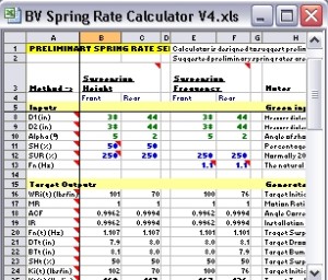 |
Click on the picture at left to download the BillaVista Preliminary Spring Rate Calculator | ||||||||||||||||||||||||||||||||||||||||||||||||||||||||||||||||||||||||||||||||||||||||||||||||||||||||||||||||||||
A few notes on using the BV Calculator:
What to Shoot For - Correlating the BV Calculator Inputs With Vehicle PerformanceAfter playing with the BV Calculator a bit, you will no doubt notice that there are two types of inputs in the calculator, which I call "measured data" and "subjective targets" respectively. The two are distinguished by the colour of the text. Green inputs are measured data - CSW, wheel travel, d1, d2, and alpha. The blue inputs are what I call subjective targets. They are the suspension height or suspension frequency and the step-up ratio. The choice of what to enter for the blue values is at the heart of the question of what suspension will work well on different vehicles for different terrain and use. There are no easy answers to that question, and no formula that will tell you what to use. The experience of others and our own testing will best help us to arrive at suitable values to enter into the BV Calculator, depending on our rig and its intended use. The following information may provide a place to start:
Anti-PitchFor medium to high speed use, normally suspension frequency will be 10-20% higher in the rear than the front. The reason the rear suspension should normally be higher frequency (stiffer / quicker) in the rear than the front is to help combat pitching. Pitching is a front-to-rear up and down motion when one end of the vehicle is going up while the other end is going down. In other words, it is a nose up / nose down oscillation. It is an extremely unpleasant sensation that is, at best, uncomfortable, and at worst can lead to a complete loss of control. Depending on the suspension in question, the speed, and the frequency of the bumps, unchecked pitching will cause the vehicle to porpoise up and down and may even lead to it somersaulting out of control. Best to be avoided then! Pitching is caused by the front of the vehicle rising over a bump, then the front comes down just as the rear goes up over the bump, then the rear comes down. That's bad enough over a single bump, but If there is a series of bumps the cycle continues, often amplifying as it goes, and the car can quickly get out of control. What's needed then, is different frequencies front to rear so that the rear is "quicker" than the front, allowing it to "catch up" over the bump so that the front and rear suspension tend towards working together instead of pitching up and down. Essentially, we want the front and rear suspension to move simultaneously because when they do there can be no pitching. Of course, we can't alter time and space, so the front is going to hit the bump first. But if the front has a lower frequency, it will take longer to react over the bump, meanwhile the rear comes over the bump, and because of its higher frequency catches up to the front and the front and rear tend back towards working simultaneously. Obviously, the wheelbase and the car's speed play a factor here as they determine the time between the front and the rear hitting the bump, and therefore the amount by which the rear should be stiffer (higher frequency) than the front. You can actually calculate the amount by which the rear should be higher frequency, but the calculation is only valid for a single speed. If you have a common or average speed in mind, a speed at which you wish to minimize pitching, then you can calculate front to rear frequency difference as follows: The time between front and rear hitting a bump is the time it takes the car to travel its own wheelbase. This can be calculated as: Twb= (0.0568 * WB) / S Where: Twb = Time to travel wheelbase in seconds WB = wheelbase in inches S = speed in mph. e.g. at 40 mph, the time it takes my 105" wheelbase buggy to travel its own wheelbase is: Twb = (0.0568 * 105) / 40 So, in order for the front and rear to work simultaneously (at 40 mph), I need the rear suspension to react or cycle 0.1491 seconds faster than the front. The time it takes the suspension to cycle is called the "period" and is easily calculated from the frequency. The period is one,divided by the frequency: P = 1 / Fn. Therefore, if we know the frequency of the front, we can calculate the period, and then the period of the rear should be that number MINUS the time to travel the wheelbase, and once we have the period of the rear, we can calculate the required frequency for the rear. Let's do an example: Data: Wheelbase (WB): 105" What should the rear frequency be? Time to travel wheelbase in seconds: Period of front suspension: Period of rear suspension: Frequency of rear suspension: So my resulting frequencies would be Front - 1.107 Hz, Rear - 1.326 Hz; with the rear 19.8% higher than the front. A moments reflection should show us that the time to travel the wheelbase is key, and therefore the shorter the wheelbase, or the higher the speed for which we optimize, the smaller the required difference between front and rear suspension frequency. Also, remember that this calculation is valid only for a single speed, so it isn't a magic number. Obviously picking the speed is critical, but again there's no magic answer, you have to pick the speed at which you wish to minimize pitching - it could be average course speed or comfortable cruising speed or some other figure and then balance this against the competing fact that the higher the speed, the less the frequencies need to differ but the more detrimental to handling the effects of pitching will be. The same is true of wheelbase. Obviously we don't tend to intentionally change wheelbase during a race or run, but the shorter the wheelbase the less the frequencies need to differ while at the same time the shorter the wheelbase the more detrimental to handling the effects of pitching will be. And of course, this is only one method, and is by no means a rule. There may be perfectly valid design reasons for having equal front to rear frequencies, or even higher frequencies at the front. Certainly in a racecar on a good surface the search for optimal aerodynamics and weight balance will likely completely outweigh this anti-pitching design criteria. Once again, we see that the search for optimal suspension design is a matter of balance and that a certain amount of testing and evaluation will be necessary - I can't give you the answers - just place from which to start. Of interest, and in out favour though, is the fact that we don't need to alter the suspension in any way to test and evaluate different frequencies - we can do so simply by adding or removing weight. Recall that the equation for frequency is: Fn = sqrt ((386.088 * WR ) / CSW ) / 2pi and therefore depends only on the wheel rate and corner sprung weight. If we leave the wheel rate alone, by changing the corner sprung weight we can alter the frequency and test that way. In summary, here are the basic equations and units again for anti-pitching suspension frequency calculations: Time to travel wheelbase (Twb) = (0.0568 * WB) / S Where: Twb = Time to travel wheelbase in seconds WB = wheelbase in inches S = speed in mph. Period = 1 / Frequency Rear Period (Pr) = Front Period (Pf) - T Front period (Pf) = Rear Period (Pr) + T Frequency = 1 / Period The BV calculator includes a worksheet to calculate different front to rear suspension frequency requirements to optimize ant-pitching for a given speed. Below is a table of results generated from the tool that shows the interesting trend that the faster the speed, the less the difference between front and rear frequencies needs to be for anti-pitch.
TrendsIn the past, the general trend for performance cars was to use frequencies as high as tolerable (i.e. wheel rates as high or stiff as practicable). More recently the trend as reversed and wheel rates are kept as soft as possible to better allow the tires to follows road irregularities. The situation is reversed in off-road vehicles. In the early days of ramp-crazy flex-mania, wheel rates were designed as soft as possible - so much so that some rigs would practically flop on their sides while the wheels remained on the ground. This trend has recently begun to reverse as well, so that stiffer wheel rates (higher frequencies) are being used to better balance high and low speed performance as well as deliver a reasonable amount of roll resistance during off-camber driving. As with all things - balance and compromise are key, and the solution for off-road rigs is probably something like "as soft as possible while being as firm as necessary". It is my fervent desire that this article serves to introduce many of us in the off-road world to the concept of suspension frequency, so that we can begin to build a body of knowledge and experience about what frequencies work well in different situations - the beauty being that I don't have to know your spring rates or corner weights to compare my frequency to yours. Interpreting the BV Calculator's Results - Prepare to Tune (or Start Over)OK, so you've accurately measured your rig's weights and dimensions, decided on a target suspension frequency, and have played with the BV Calculator and its inputs to get some results - some preliminary spring rate calculations. Is that it? Do you rush out and buy some springs and install them and go? Unfortunately not. You will have noticed that I keep referring to the calculator's output as preliminary spring rate calculations. That's because we're only just getting started. It is important to understand the limitations of the results the calculator provides - particularly if you're using suspension height as your input or if you're just taking a SWAG at the frequency you want. What if the spring rates generated by the calculator fall short in some other area? For example, what if the spring rates suggested by the BV Calculator will result in a wheel rate that is too soft to provide any appreciable roll resistance or too firm for ride comfort? Recall the seven goals of suspension design: is a matter of achieving the best balance between these often competing goals:
If you use the Calculator with SH as your primary target, the results generated by the BV Calculator address only the second of these. If you use Fn as your target, then the calculator's results can potentially address multiple goals - depending on the accuracy of the match between what you enter as a target Fn and what it is that you are actually aiming for in terms of ride & handling. Either way, selecting preliminary spring rates is not a magic solution to the entire problem of suspension design. Some of the design goals to be considered in spring rate selection cannot easily be quantified with equations in a spreadsheet, even of you use suspension frequency as the target. Chief among these factors are the desired roll resistance and even the all-important assessment of ride quality, both of which can be highly subjective. Consider:
The good news is, there's plenty we can do about it. Again, if we begin with Fn, the next step is tuning for suspension height by using spring length options, the adjustable top spring seat, preload, and helper coils. After that we still have to consider shock valving and use of other tools such as anti-roll bars and bumpstops. It isn't easy and there is no simple answer or magical formula I can give you to arrive at the perfect setup to meet all seven goals. It is inevitable that from this point forward a good deal of testing and evaluation and tuning will be required if you are to extract the maximum performance from your coilovers. However, there is a great deal more tech for us to consider, which we shall in Part 3 and beyond. Combined with a solid understanding of the contents of this article, you can significantly reduce the time and effort (and funds!) you will have to expend reaching the magic balance. What the BV Calculator does is provide you with a pretty good place to start. So, where do we go next? The short answer to that is: spring length choice and spring seat adjustment. The long answer, however, will have to wait for part 3 - coming soon so stay tuned. SummaryOK, so we've covered a lot of ground in Part 1, and hopefully covered all of the basics that will serve as a firm platform for when we explore more advanced topics. Don't worry if it takes a few reads to get it all down - I didn't write it all in one shot! That said, let's recap the major points:
Closing NotesIt is, of course, entirely possible to use the BV Calculator with SH as the goal, have no grasp of Fn, generate some preliminary spring rates and then rush right out and buy springs and start installing things. In fact, people have been using this approach since coilovers began appearing on offroad rigs - with decidedly mixed results! I began the article by suggesting that there are not really any "invalid" approaches to suspension design (although some are certainly better than others) so I am somewhat obliged to say that you may, if you wish, do just this. I certainly don't recommend it though. If, however, you're the terribly impatient kind, and you're so jazzed at this point you simply must run out and buy springs and get at it - there are a few points I must leave you with so that you may at least avoid total disaster: Spring Length Spring length is a really big deal, and part of the intricate balance that will deliver the top performance we seek. If you can't wait for Part 3 then I recommend you buy a main spring with a length equal to the travel of the shock (so the DRS doesn't fall of the body at full droop) and a tender spring with a length that will put your coilover top spring seat in the middle of its adjustment range - which usually means a spring 2-4" shorter than the main spring, plus a helper coil and a triple-rate slider. If you go this route, you will be faced with many compromises, even if you're not aware of them, but it will get you on the road and if you're willing to spend a lot of time and money testing and swapping different springs, you may eventually end up with a decent setup. For the rest of us, understanding the tech in Part 3 will provide a much more solid foundation for our eventual testing and tuning. Buying Coilover Shocks There's plenty of choice in the market, I have experience with a few brands, but certainly not all. Personally, I have been running 16" 2.0 remote reservoir Fox Racing Shox for a number of years and they have performed extremely well and stood up amazingly to my abuse and neglect in a harsh 4-season environment. In fact, I once bent a rod quite badly, but continued wheeling on it for several trips without a leak, and as luck would have it, some time later tagged a tree pretty hard and bent it back to darn near straight and that's how it has stayed - it was pretty impressive. I particularly appreciate the quality of the hardware and the finish. The one-page "manual" you get is less than impressive - but I guess that's why I get to write articles like this. Their years of experience, the fact that the company is virtually guaranteed to be around in the future, and the fact that you can buy any conceivable part at very reasonable cost are all good qualities too. Buying Coil Springs The quality of the springs you use are every bit as important as the shocks. Cheap springs will waste your time and frustrate your efforts if they "take a set" or change length after use. A properly engineered and manufactured quality coil spring should not lose free length or installed height under normal conditions. Also, cheap coils tend to have less travel before they coil bind than quality springs. There's simply no way you can properly design and tune a coilover suspension without knowing the exact specifications of the springs - particularly the Free Length (Lo), Block Height (Lc), Travel (max defection) (Sc), and Force Limit (Fc). Every spring is sold with a rate specified, but many do not include these other vital specs. We haven't covered the practical application of all the specs yet, but trust me, they are critical. I have been using Eibach springs for years, and can tell you that even after many years under a heavy, frequently abused rig any change in length that might have occurred is less than I can measure with a tape measure. Also, Eibach have an excellent catalogue, a copy of which is linked below in the "resources" section, that clearly lists every spec you need to know for every spring they sell - that is damn useful information and I'm impressed with how they publish it. Where you buy your shocks and springs is an important consideration too. If you're going to rush ahead to buying and installing, or if perhaps you don't have the time or inclination to learn all the tech, you need a vendor with knowledge and experience. I've been using Dave Schlossberg and his company PolyPerformance for years and have nothing but good things to say about them. What's Next? We've come a long way - and have plenty of road left to travel. Next is Part 2 where I'm going to cover some hands-on tech - it's good to break up the mental gymnastics with a good greasy-hands shop session. Following that, in Part 3 we'll pick the theory back up starting with spring length, suspension height tuning, preload and helper coils. Until then... Resources:
References:
Sources |
|||||||||||||||||||||||||||||||||||||||||||||||||||||||||||||||||||||||||||||||||||||||||||||||||||||||||||||||||||||
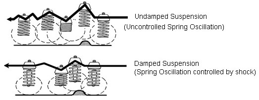
.jpg)
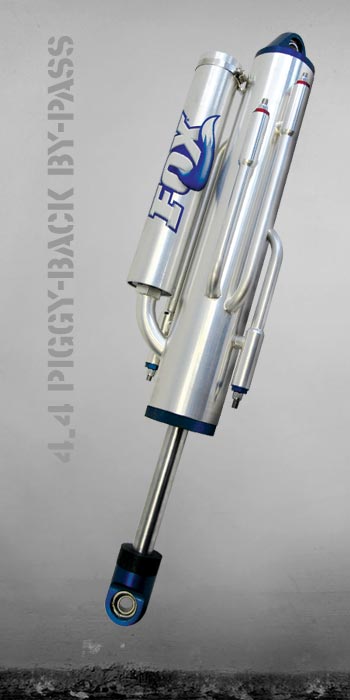
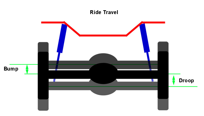
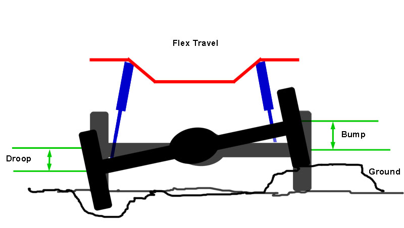
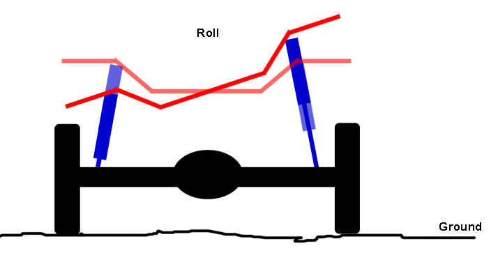
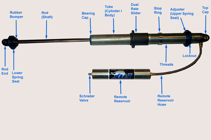
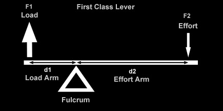
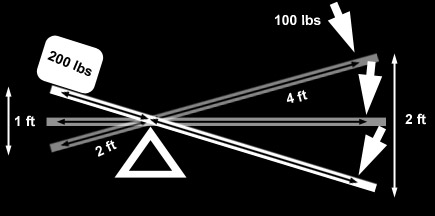
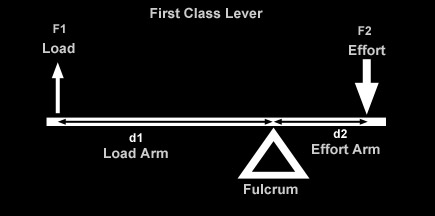
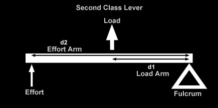
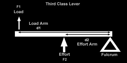
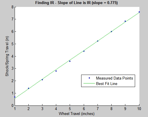
|