 |
Installing a Trailer Brake Controller By Bill "BillaVista" Ansell |
My '07 Chevy 2500HD gets a Tekonsha ProdigyIntroductionHere's how to install an electric trailer brake controller in a late-model GM truck ('99-'07-Classic; Silverado and Sierra). |
 |
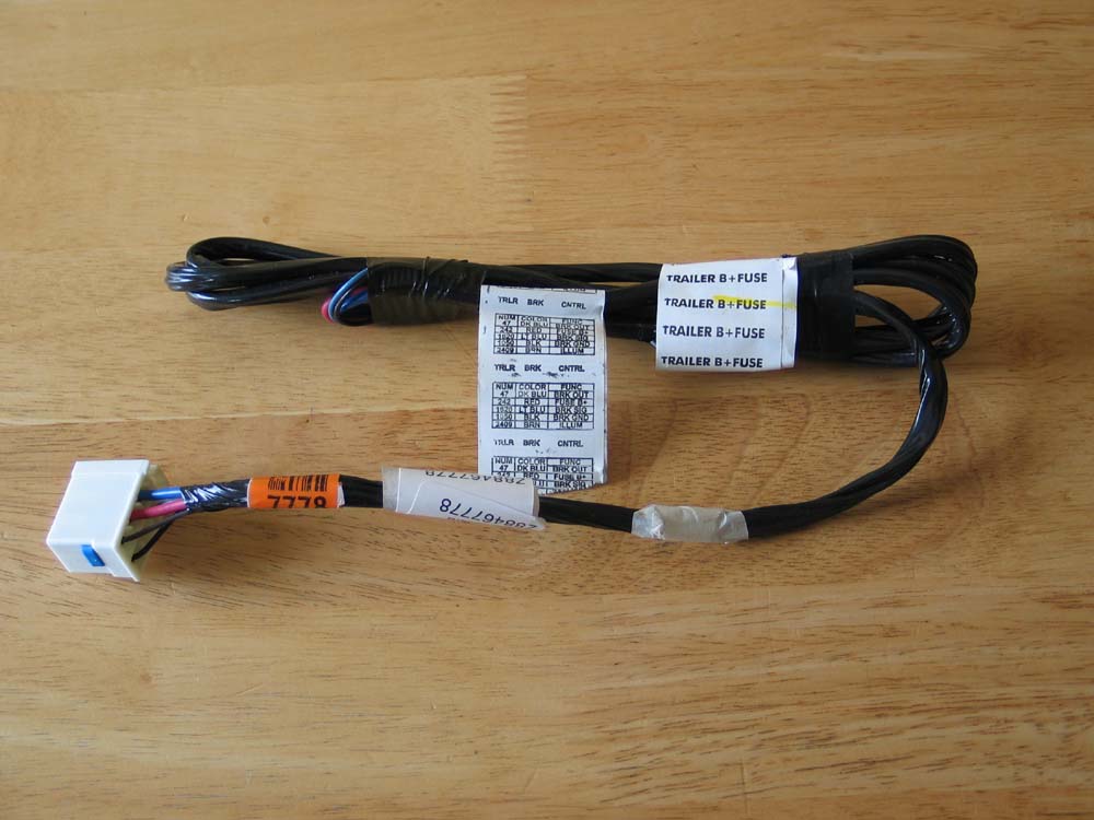 |
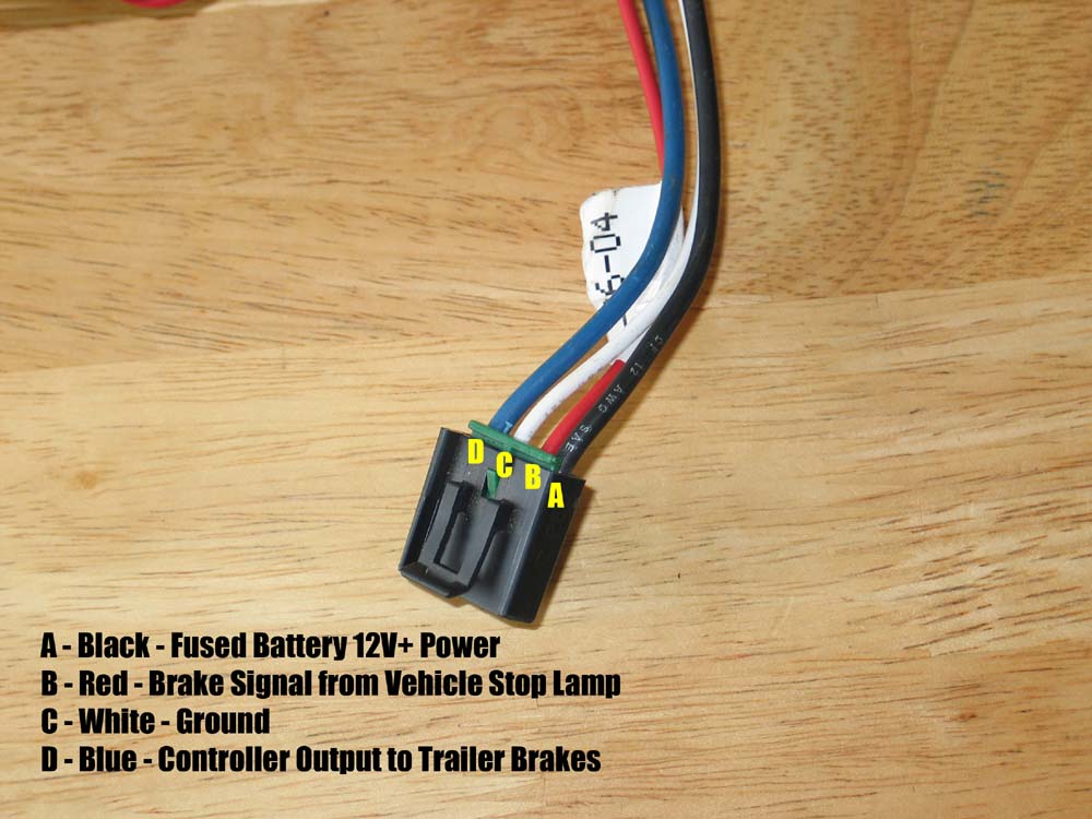
If your truck came with the HD Trailer Towing Package (RPO code Z82) it will come with a "Brake Controller Pigtail" wiring harness in the glove box. These are also available separately from the dealer. This is what it looks like. It includes a five wire harness with a connector on one end and blunt cut wires on the other end. It also comes with a 40-amp "B+ Trailering J-Case fuse" which will be securely taped to the wire bundle. There will also be a small instruction tag attached. Here is a SCAN of that tag in .pdf format. |
||||||||||||||||||||||||||||||||||||||||
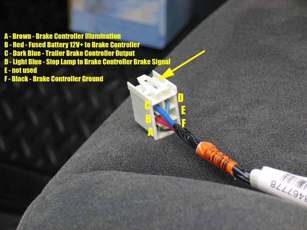 |
Here is a diagram of the connector showing the wire colours and pin-out of the connector.
|
||||||||||||||||||||||||||||||||||||||||
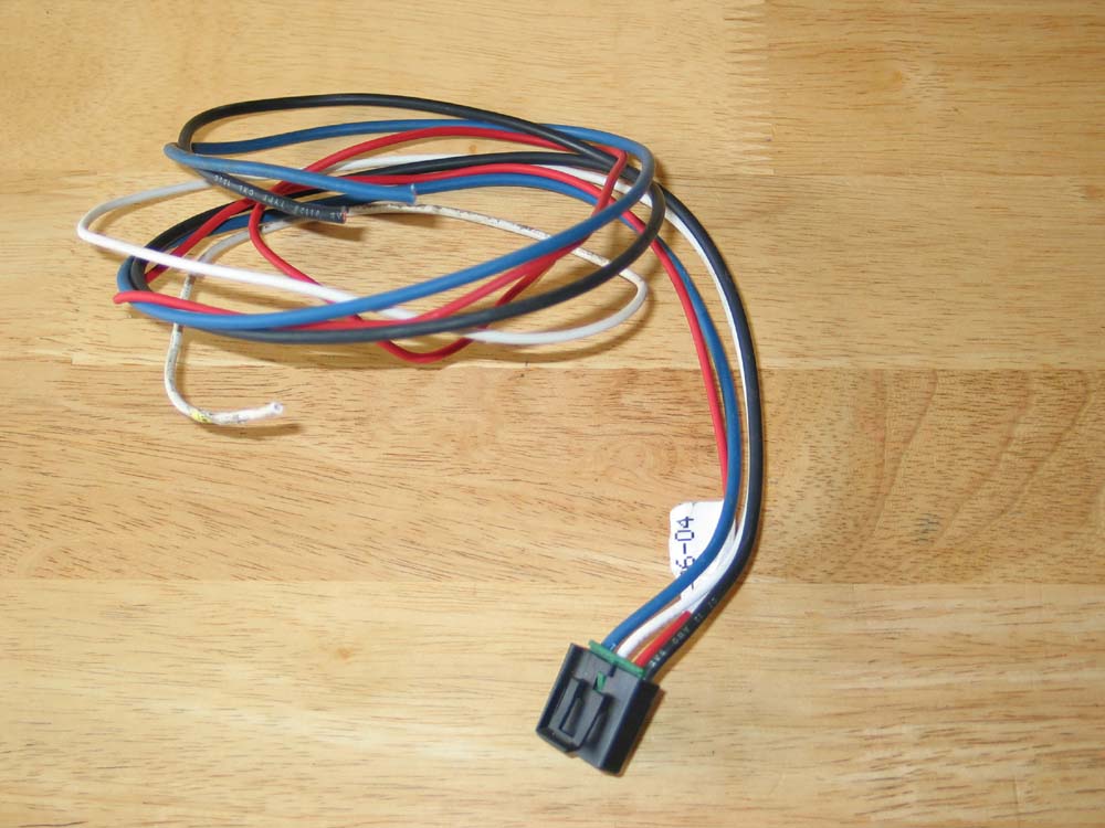 |
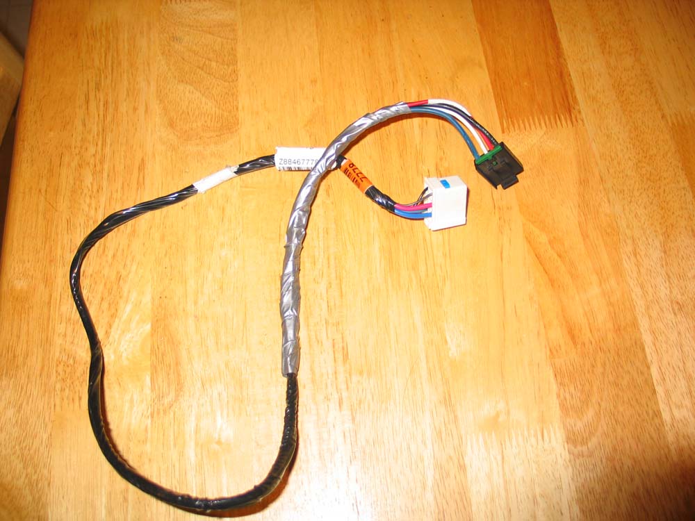
This is a picture of my brake controller's wiring harness. I used a Tekonsha Prodigy controller. Basically, installation involves plugging the the GM Brake Controller Pigtail into the vehicle using the attached connector (pictured above); splicing the wires of the pigtail to the correct wires of the Prodigy's harness; and then plugging the Prodigy's harness into the controller itself. |
||||||||||||||||||||||||||||||||||||||||
For those that don't want to connect the wires together themselves, Tekonsha does sell pre-made harnesses with the correct connections made and the correct plugs already installed on each end. The only problem with this approach is that the harness will be a "universal" length ( I think they'er about three feet long), which usually means way too long. Personally I prefer to do a little soldering myself and keep the wires short and neat. If you want to use the pre-made harness the part numbers are as follows: 2003 to 2005 GM Trucks and SUVs - p/n 3015 |
|||||||||||||||||||||||||||||||||||||||||
 |
Here is a close-up of the wire colours and pin-out of the Prodigy connector.
|
||||||||||||||||||||||||||||||||||||||||
To Connect the two sets of wires together, we use the following table:
|
|||||||||||||||||||||||||||||||||||||||||
 |
Here's the completed harness. Before cutting the wires to length and soldering it's a good idea to trial-fit the controller in the truck and measure the length required for the wires. |
||||||||||||||||||||||||||||||||||||||||
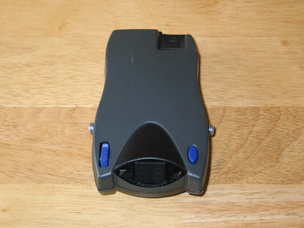 |
Top view of the Tekonsha Prodigy. | ||||||||||||||||||||||||||||||||||||||||
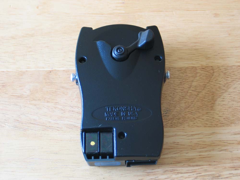 |
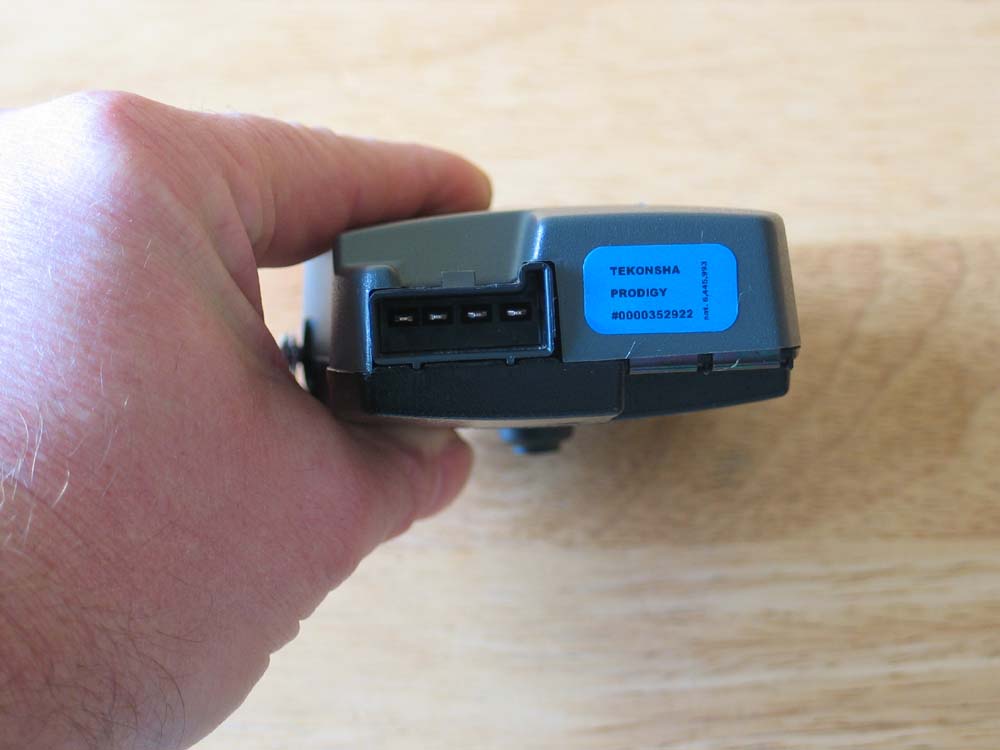
Bottom view of the Prodigy. | ||||||||||||||||||||||||||||||||||||||||
 |
Rear of the Prodigy showing the connector port. | ||||||||||||||||||||||||||||||||||||||||
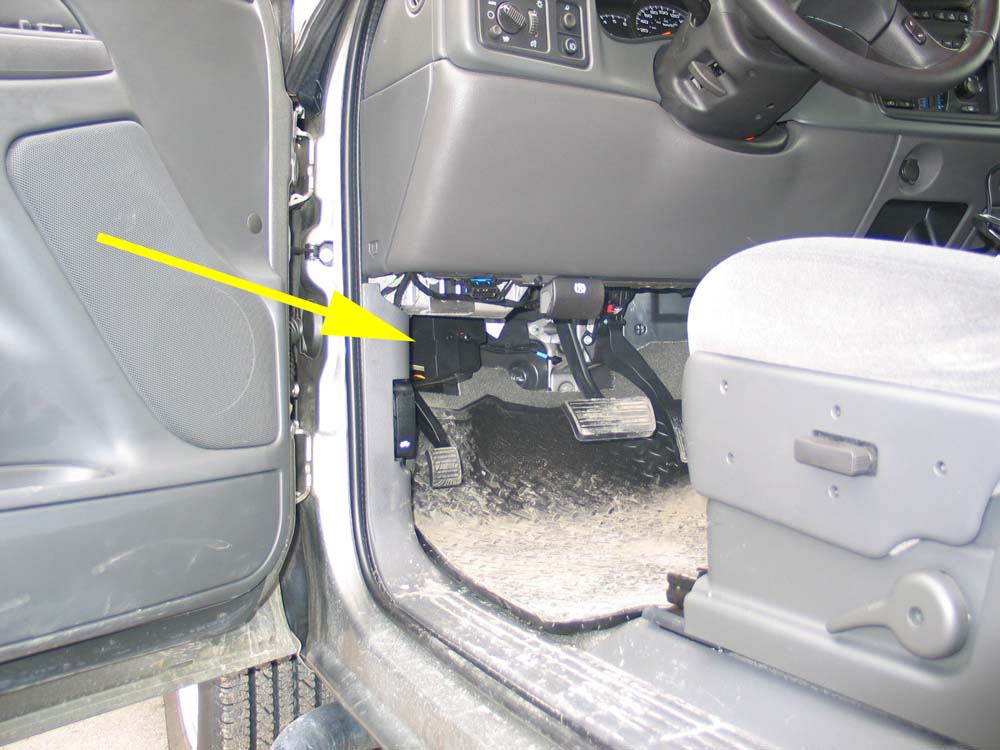 |
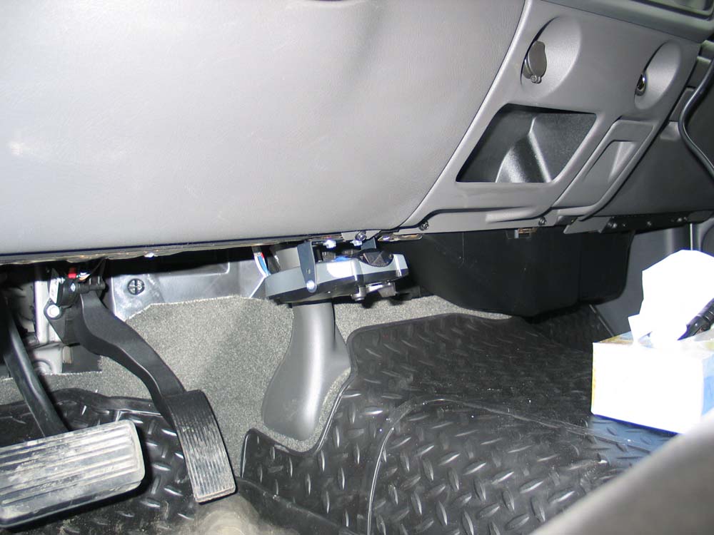
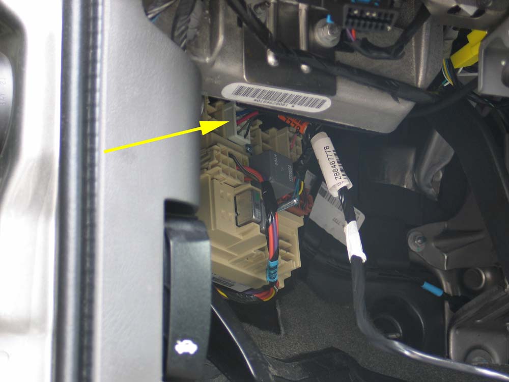
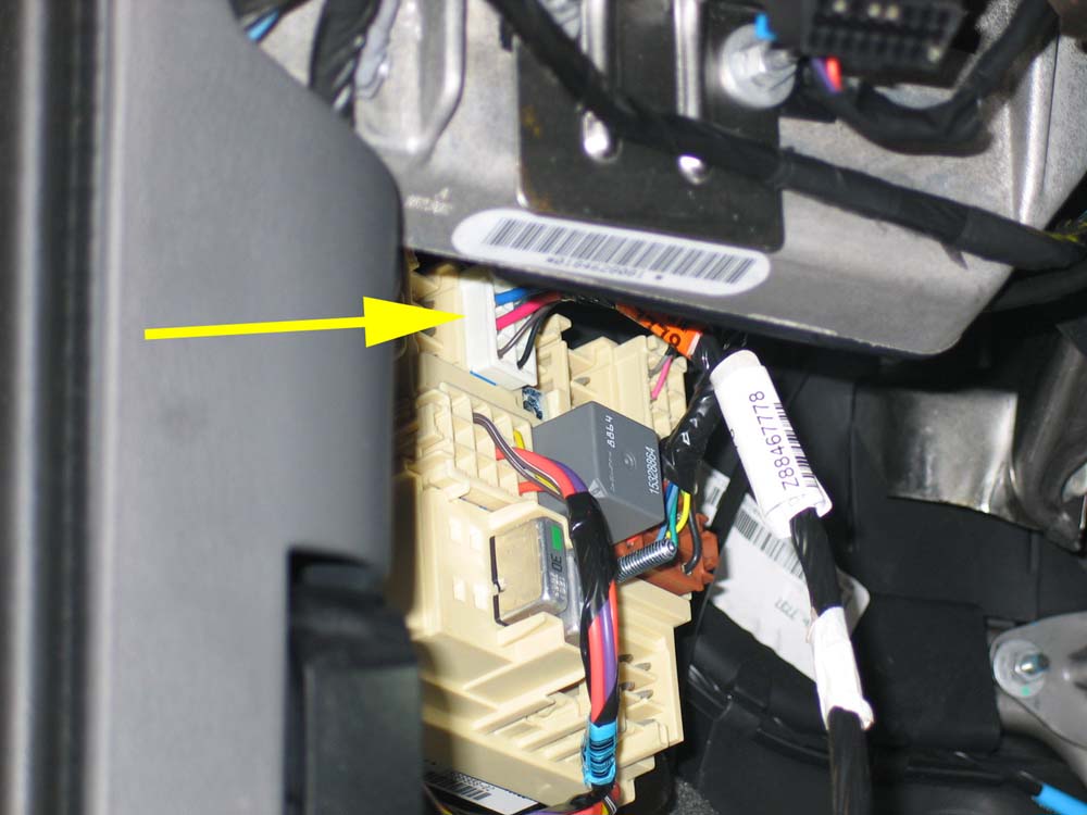
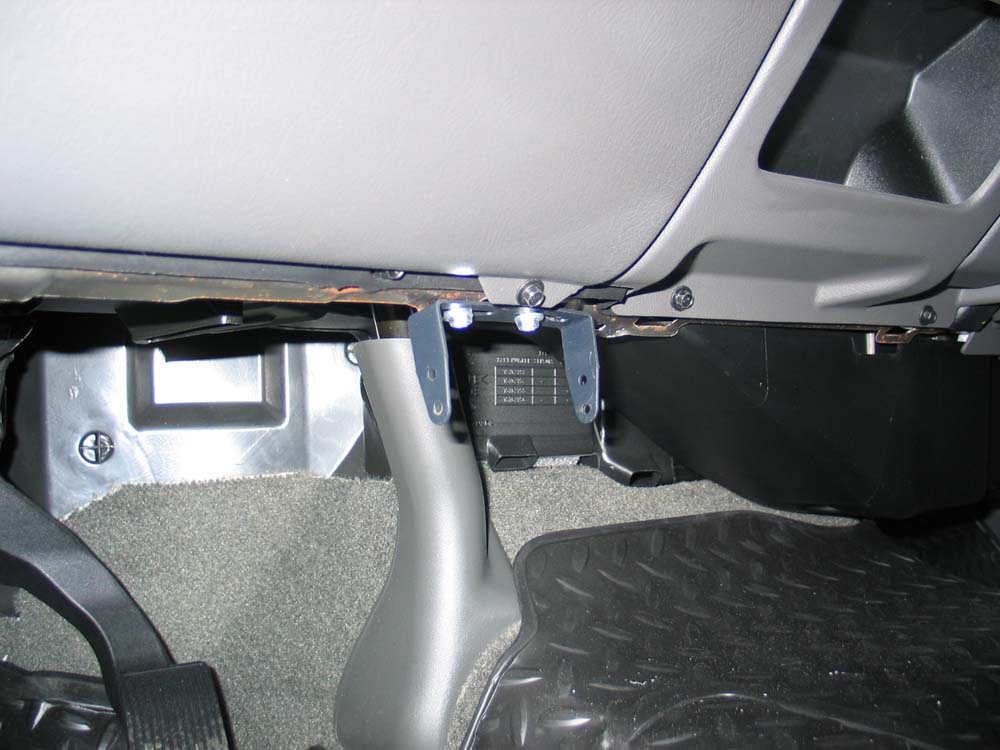
With the harness completed and the controller in hand, the first job is to locate the "interior electrical panel". It is here that we will plug in the GM-connector end of the harness. The panel is located on the left side of the driver's foot well as indicated here by the yellow arrow. |
||||||||||||||||||||||||||||||||||||||||
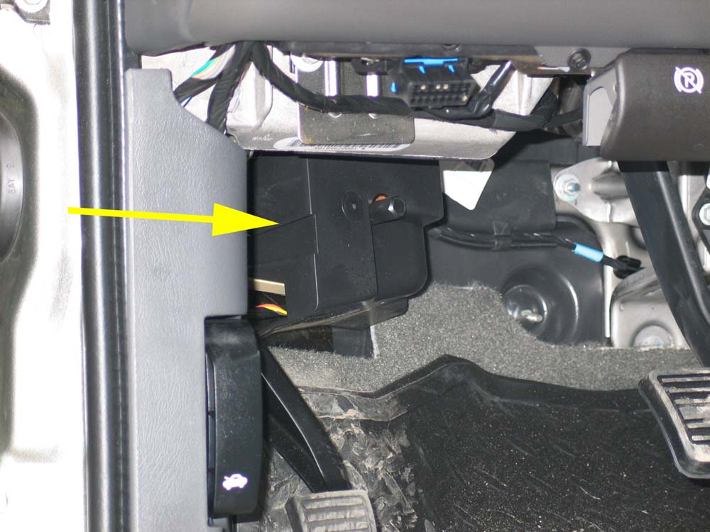 |
Close up of the location of the interior electrical panel. | ||||||||||||||||||||||||||||||||||||||||
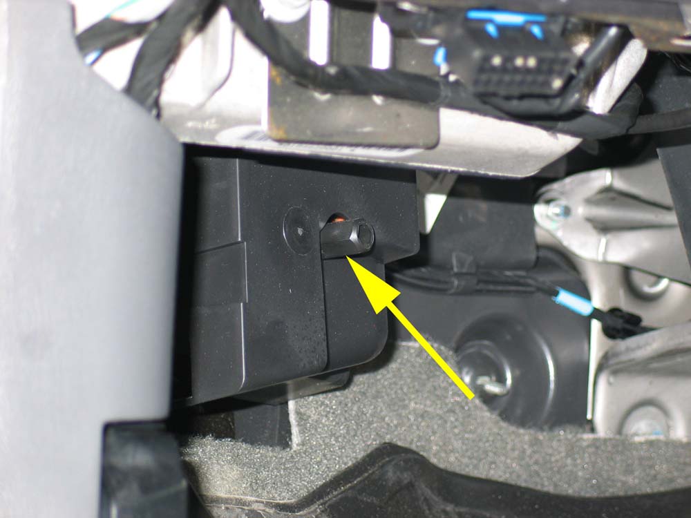 |
To remove the cover, first unscrew and remove the plastic nut. No tools are required, it's only finger tight. | ||||||||||||||||||||||||||||||||||||||||
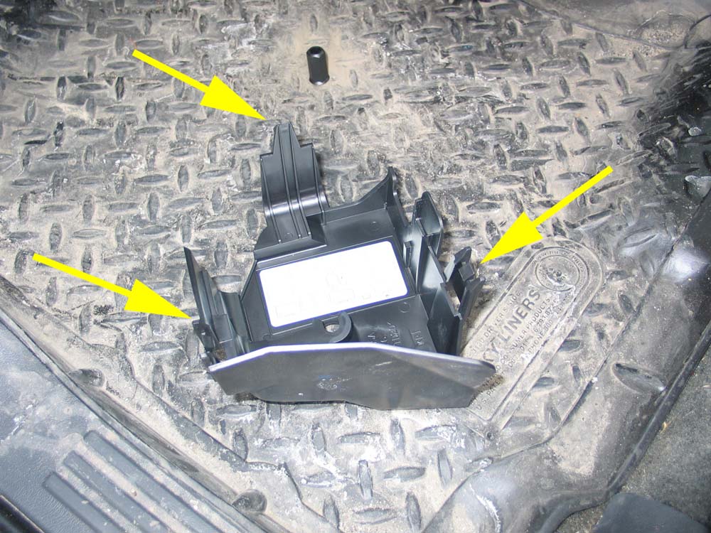 |
With the nut removed, there are 3 plastic clips (identified here by the yellow arrows) you need to gently release to pull the cover off. | ||||||||||||||||||||||||||||||||||||||||
 |
Under the cover, the panel looks like this. | ||||||||||||||||||||||||||||||||||||||||
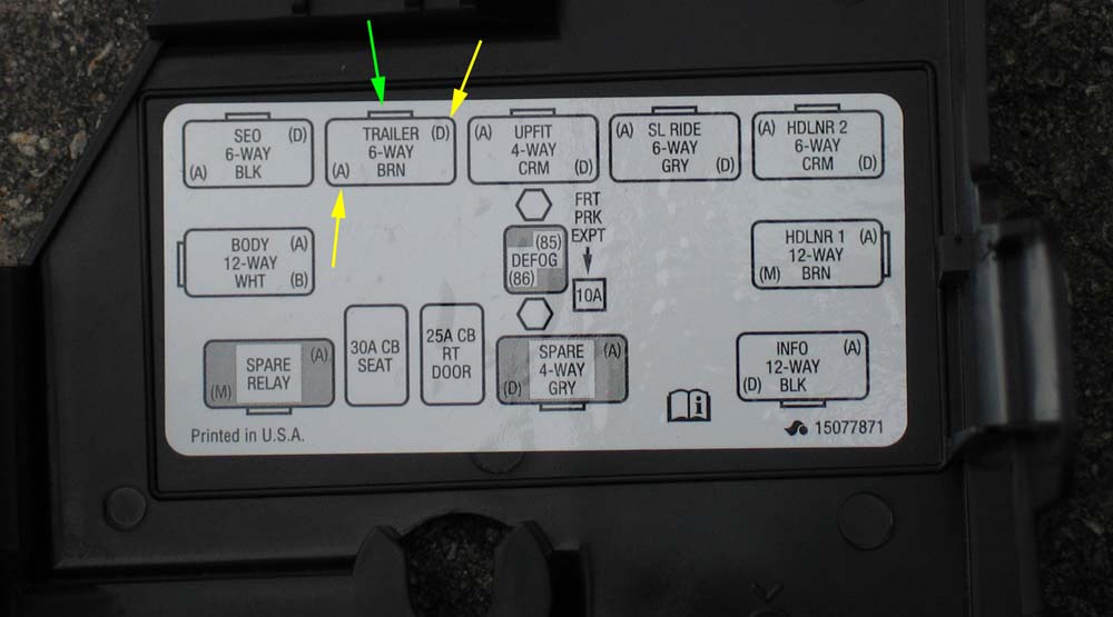 |
Inside the cover there is a schematic of the sockets and connectors. The Trailer brake controller socket is on the top row, second from the left. The green arrow here indicates the diagrammatic representation of the clip on the pigtail, which shows that the connector is inserted with the clip at the top. The yellow arrows indicate the A and D pin locations of the socket, confirming that the connector is inserted "clip up". |
||||||||||||||||||||||||||||||||||||||||
|
Here the yellow arrow shows the clip on the top of the connector. | ||||||||||||||||||||||||||||||||||||||||
 |
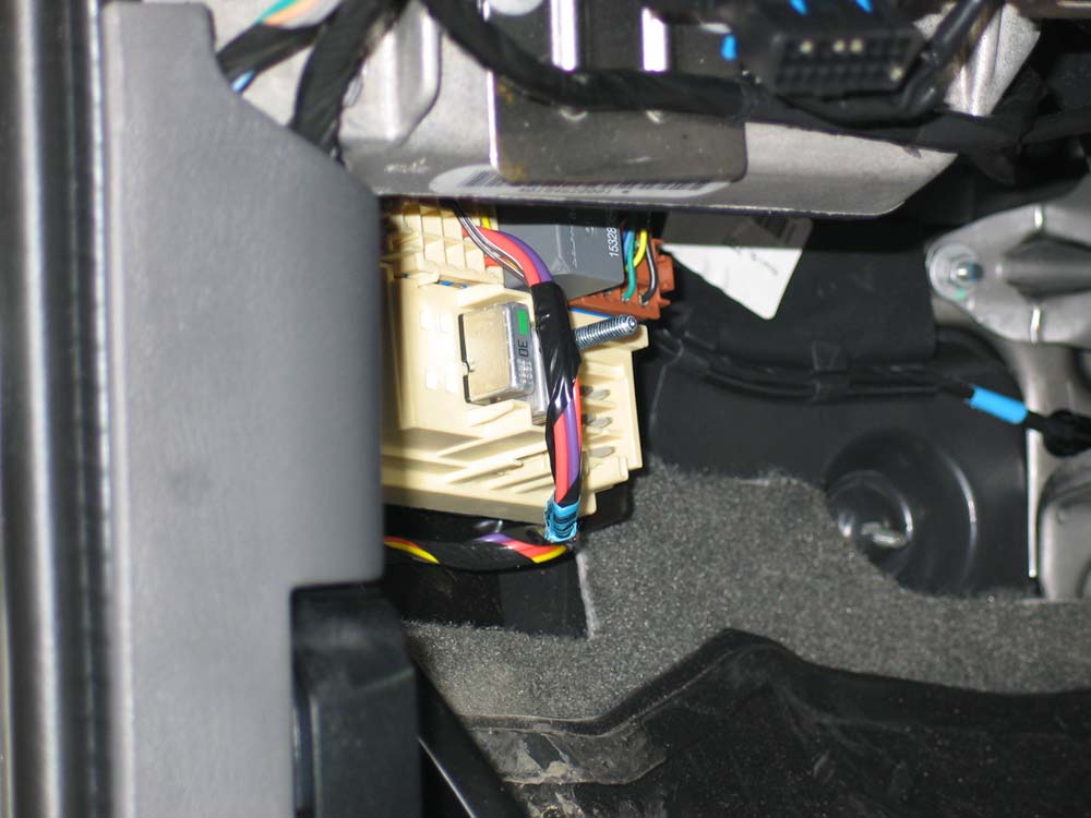
Yellow arrow indicates the pigtail connector plugged into the correct socket in the interior electrical panel. | ||||||||||||||||||||||||||||||||||||||||
 |
Close-up of brake controller connector plugged into interior electrical panel. | ||||||||||||||||||||||||||||||||||||||||
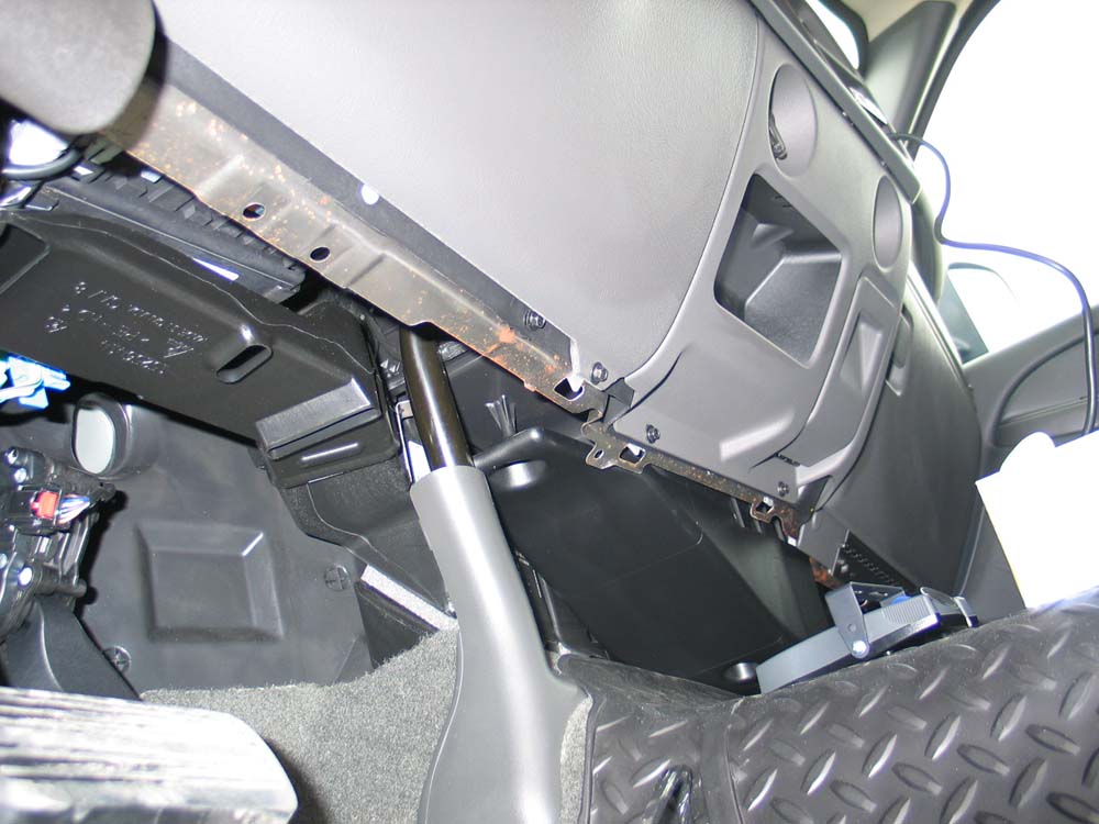 |
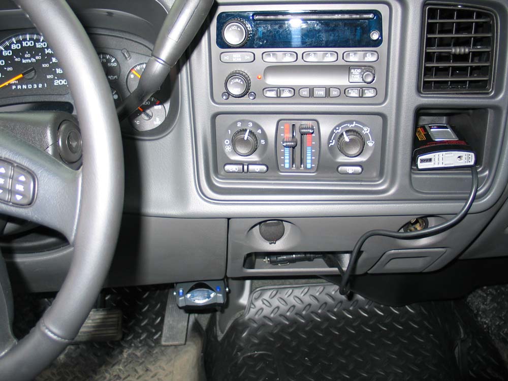
With the pigtail plugged in, the next step is to choose a location for mounting the brake controller. Not wanting to drill holes in my new dash, I knew my options would be limited to finding a location along the bottom edge of the dash. That way I could drill through the metal edge without marking up the vinyl. This pic shows the area in question. |
||||||||||||||||||||||||||||||||||||||||
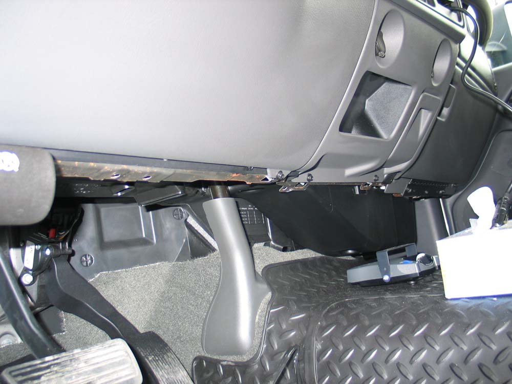 |
Another shot of the general area where you can mount a controller without marking up the dash. I experimented with several locations. I ruled out the area to the left of the steering column because there was no location there that didn't interfere with either the parking brake release or the OBDII diagnostic port connector. |
||||||||||||||||||||||||||||||||||||||||
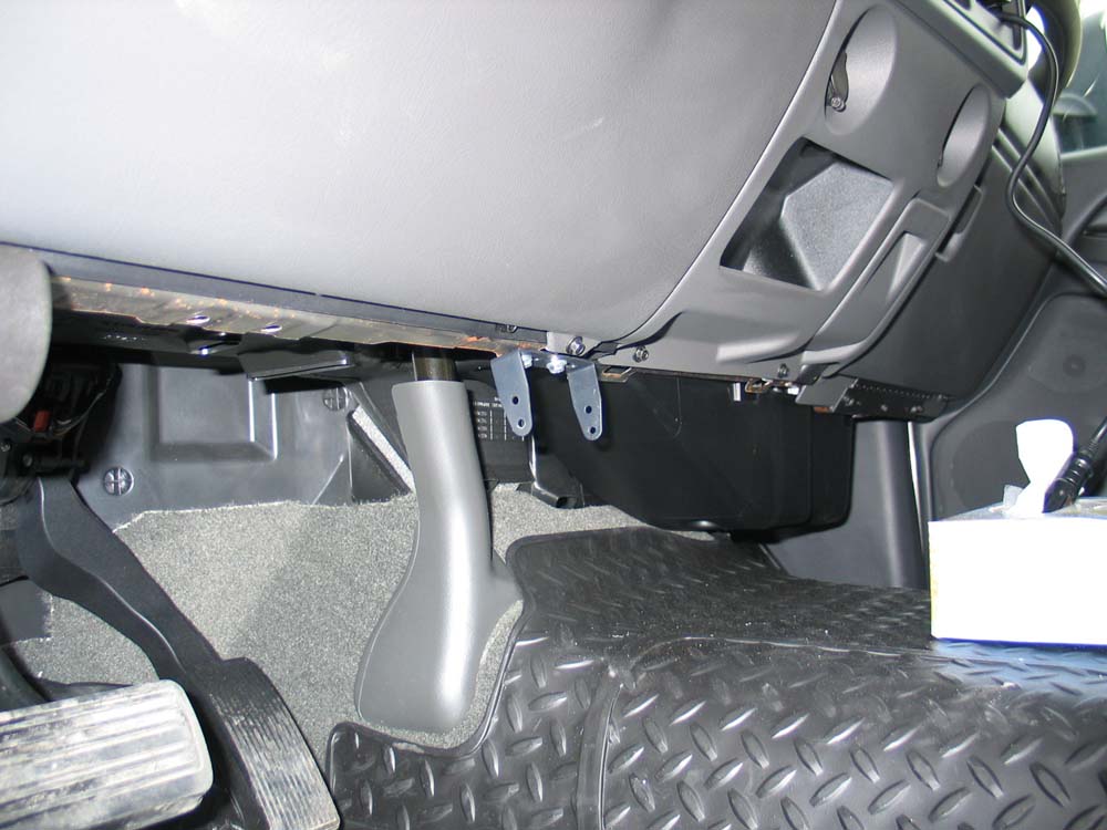 |
The location I settled on was on the far right, just before the centre panel. Here you can see the controller's mounting bracket installed in that location. |
||||||||||||||||||||||||||||||||||||||||
 |
I attached the mounting bracket to the bottom lip of the dash with a couple of self-drilling screws. | ||||||||||||||||||||||||||||||||||||||||
|
The final step is to attach the controller to the bracket, plug the connector into the Prodigy, and tuck the wiring harness up under the dash, securing it with a couple of zip ties. | ||||||||||||||||||||||||||||||||||||||||
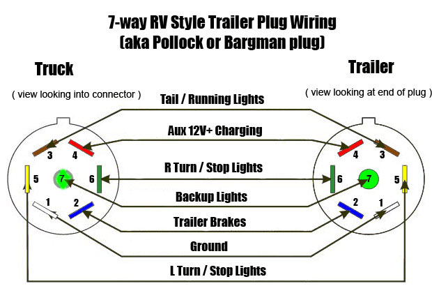
If you read the instructions on the tag that comes attached to the GM brake controller pigtail harness you will notice that Step 4 says to "...plug in the 40A B+ trailering J-case fuse in the stud #1 location of the UH electrical center." You could be forgiven for thinking that this fuse, therefore, has something to do with the brake controller wiring. In fact, it does not. The fuse that controls the power to pin B of the brake controller socket is the pink 30 Amp fuse installed in stud #2 of the under hood fuse panel (UH electrical centre). The green 40-amp "B+ Trailering J-Case fuse" that comes taped to the GM pigtail is to be installed in the under hood fuse panel, in Stud #1, to provide 12V+ power to pin 4 of the trailer connector at the rear of the truck. This power feed is used for powering accessories on the trailer such as interior lights or charging the battery that powers the trailer's breakaway brakes. For reference the following diagram and chart illustrate the "standard" pin-outs and wiring for the 7-way RV-Style trailer plug used on modern trucks.
Note that there are at least two common "standard" wire colour schemes, both identified in the above chart. There are even variations within these "standard" schemes. For example, sometimes the #7 pin's wire is orange. When in doubt, each pin's function should be checked and verified with a multi-meter or test light before any connections are made. |
|||||||||||||||||||||||||||||||||||||||||
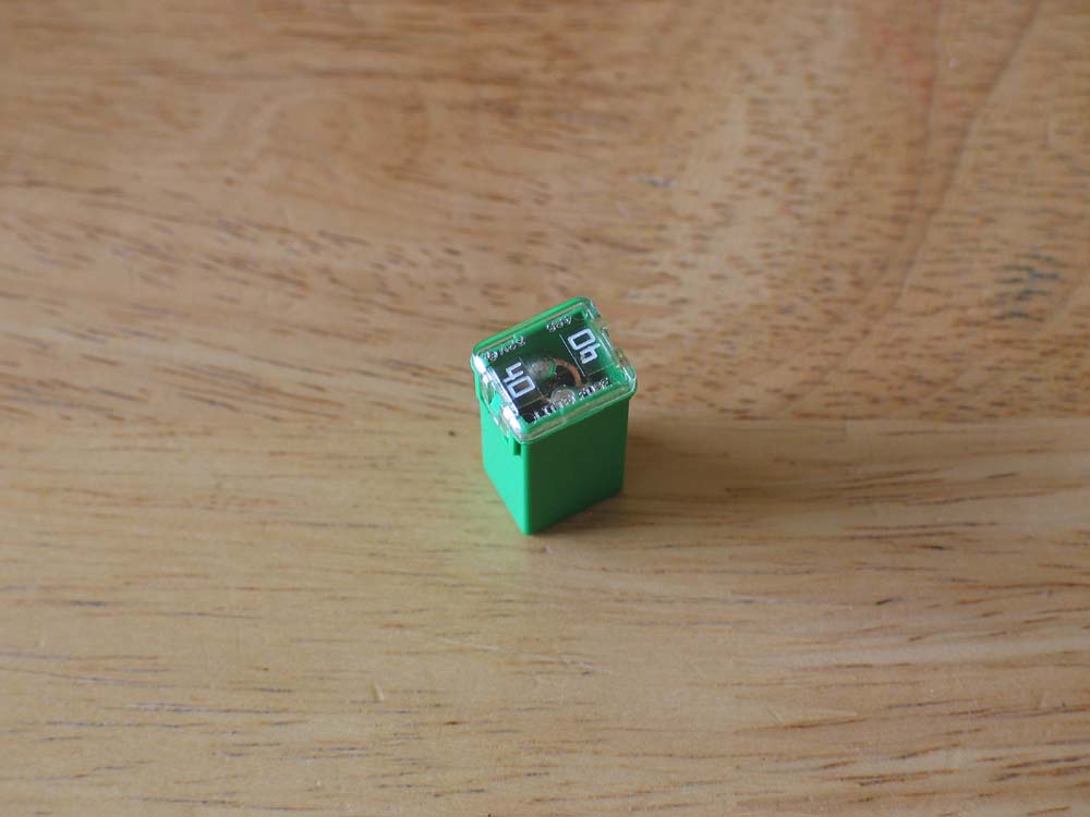 |
Let's take a look at both fuses and their locations. The 40-amp "B+ Trailering J-Case fuse" that comes taped to the GM pigtail. |
||||||||||||||||||||||||||||||||||||||||
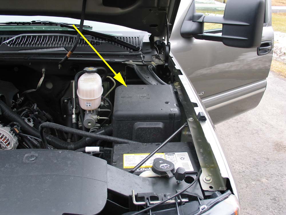 |
Location of the under hood fuse panel. | ||||||||||||||||||||||||||||||||||||||||
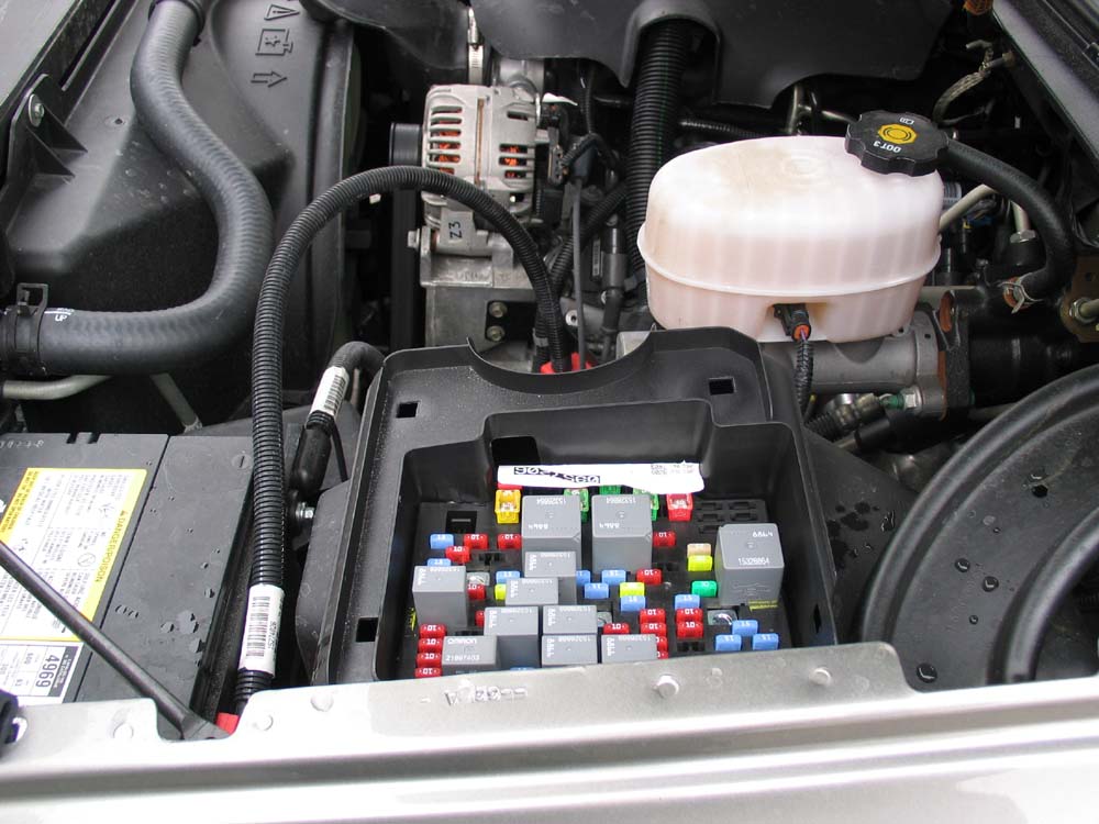 |
The cover simply pulls off to reveal the fuses and relays. | ||||||||||||||||||||||||||||||||||||||||
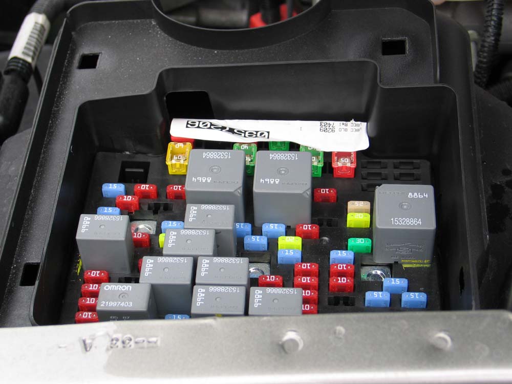 |
Both stud #1 and stud #2 are along the inboard side of the fuse panel, probably covered by a sticker as shown at the top in this picture. | ||||||||||||||||||||||||||||||||||||||||
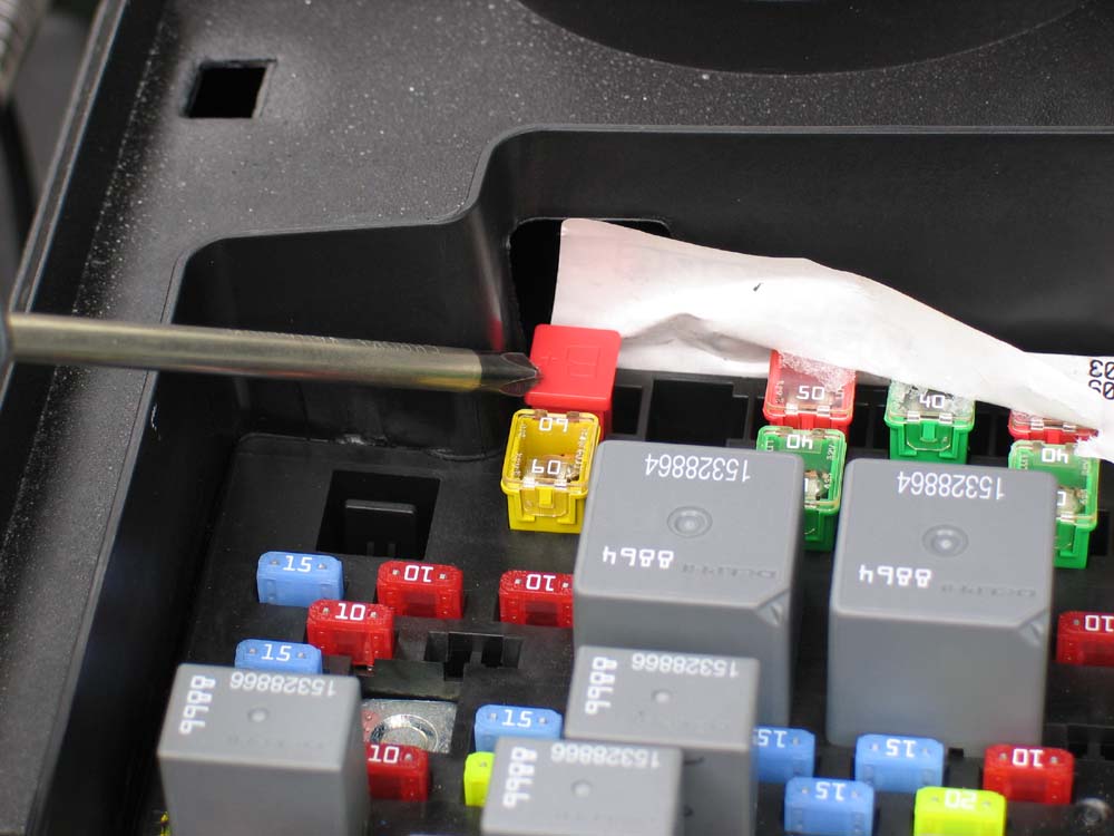 |
Peeling back the sticker reveals the dummy plug in stud #1. You must remove this plug to install the 40A B+ fuse to provide 12V+ power to pin 4 of the trailer connector at the rear of the truck. | ||||||||||||||||||||||||||||||||||||||||
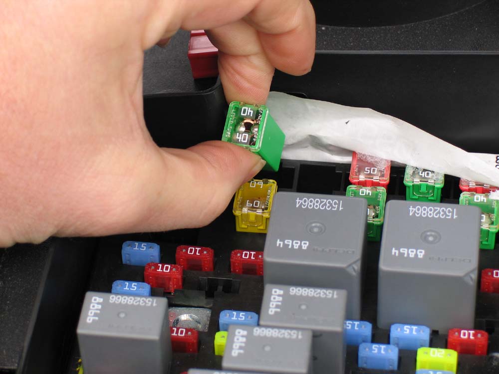 |
40A B+ fuse being installed. | ||||||||||||||||||||||||||||||||||||||||
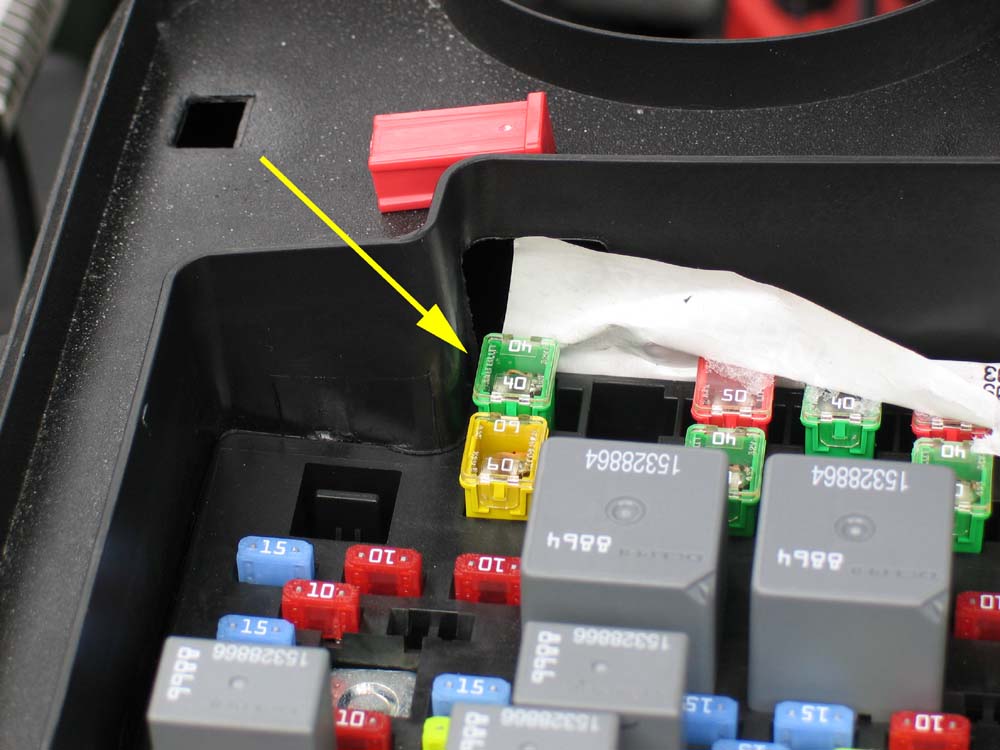 |
Installed 40A B+ fuse. | ||||||||||||||||||||||||||||||||||||||||
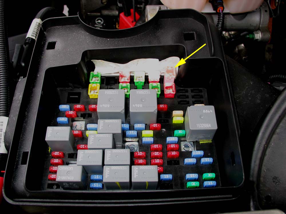 |
The yellow arrow indicates stud #2, the location of the pink 30A fuse that controls power to the brake controller wiring harness. When I had completed the installation of the Prodigy, I was at first stumped because there seemed to be no power to the controller. Fooled by the confusing GM instructions, I initially thought it had something to do with green 40A B+ fuse referred to in the instructions. The kind souls at DieselPlace.com set me straight on the fuse locations and functions, and a quick check of the fuse diagrams in the owners manual confirmed it. |
||||||||||||||||||||||||||||||||||||||||
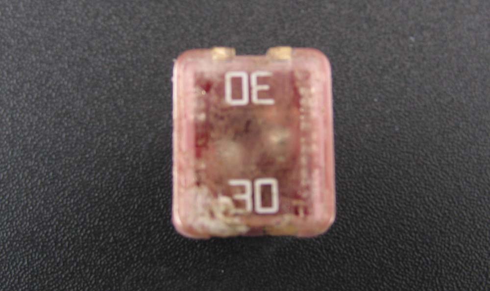 |
Examining the 30A fuse in stud #2 was initially difficult because of the residue from the sticker that GM, for some reason, saw fit to stick over the first row of fuses. | ||||||||||||||||||||||||||||||||||||||||
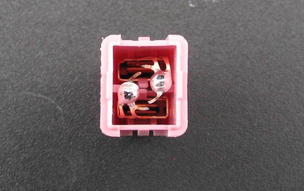 |
However, you can pop the little clear plastic cover off this style of fuse and see inside. Sure enough, mine was blown. After replacing this fuse all was well and the installation was complete. |
||||||||||||||||||||||||||||||||||||||||
 |
Picture of the final install of the Tekonsha Prodigy brake controller. | ||||||||||||||||||||||||||||||||||||||||
|
|||||||||||||||||||||||||||||||||||||||||
|